US2437256A - Auxiliary control mechanism for automatic pilot - Google Patents
Auxiliary control mechanism for automatic pilot Download PDFInfo
- Publication number
- US2437256A US2437256A US466301A US46630142A US2437256A US 2437256 A US2437256 A US 2437256A US 466301 A US466301 A US 466301A US 46630142 A US46630142 A US 46630142A US 2437256 A US2437256 A US 2437256A
- Authority
- US
- United States
- Prior art keywords
- rudder
- control mechanism
- block
- follow
- pilot
- Prior art date
- Legal status (The legal status is an assumption and is not a legal conclusion. Google has not performed a legal analysis and makes no representation as to the accuracy of the status listed.)
- Expired - Lifetime
Links
- 230000033001 locomotion Effects 0.000 description 29
- 230000001276 controlling effect Effects 0.000 description 11
- 230000007935 neutral effect Effects 0.000 description 5
- 210000002445 nipple Anatomy 0.000 description 5
- 241000269799 Perca fluviatilis Species 0.000 description 2
- 230000005540 biological transmission Effects 0.000 description 2
- 238000006073 displacement reaction Methods 0.000 description 2
- 230000002596 correlated effect Effects 0.000 description 1
- 230000000875 corresponding effect Effects 0.000 description 1
- 230000007423 decrease Effects 0.000 description 1
- 238000005192 partition Methods 0.000 description 1
- 239000011435 rock Substances 0.000 description 1
- 125000006850 spacer group Chemical group 0.000 description 1
Images


Classifications
-
- B—PERFORMING OPERATIONS; TRANSPORTING
- B64—AIRCRAFT; AVIATION; COSMONAUTICS
- B64C—AEROPLANES; HELICOPTERS
- B64C13/00—Control systems or transmitting systems for actuating flying-control surfaces, lift-increasing flaps, air brakes, or spoilers
- B64C13/24—Transmitting means
- B64C13/26—Transmitting means without power amplification or where power amplification is irrelevant
- B64C13/28—Transmitting means without power amplification or where power amplification is irrelevant mechanical
-
- G—PHYSICS
- G05—CONTROLLING; REGULATING
- G05D—SYSTEMS FOR CONTROLLING OR REGULATING NON-ELECTRIC VARIABLES
- G05D1/00—Control of position, course, altitude or attitude of land, water, air or space vehicles, e.g. using automatic pilots
- G05D1/0055—Control of position, course, altitude or attitude of land, water, air or space vehicles, e.g. using automatic pilots with safety arrangements
- G05D1/0061—Control of position, course, altitude or attitude of land, water, air or space vehicles, e.g. using automatic pilots with safety arrangements for transition from automatic pilot to manual pilot and vice versa
Definitions
- the invention relates to improvements in auto- -matic pilots for aircraft and, more particularly,
- An important object of the present invention is to provide an automatic gyro-pilot having auxiliary rudder control mechanism
- Another object of the invention is to provide an automatic gyro-pilot for bomber aircraft having auxiliary rudder control mechanism associated with the bombsight.
- Yet another object is the provision of an auto,- matic gyro-pilot with' rudder control mechanism including follow-up means transmitting motion in varying ratios depending on the rudder displacement.
- a further object is to provide an automatic gyro-pilot having rudder control mechanism including an adjustable lost-motion follow-up connection.
- a still further object is the provision of an automatic gyro-pilot having rudder control mechanism including a resilient follow-up connection.
- the invention also aims to provide an automatic gyro-pilot for bombers including auxiliary rudder control mechanism operable by changes in the direction setting of the bombsight.
- the invention further aims to provide an automatic gyro-pilot for bombers including auxiliary rudder control mechanism of the character described and provided with-manually operable adjusting means.
- Figure 1 is a diagrammatic perspective view of a gyro-pilot provided with the auxiliary rudder control mechanism and showing the servo cable connections to the aircraft control surfaces.
- Figure 2 is a view in side elevation of the rudder control unit.
- Figure 3 is a top plan view of the rudder control unit, its top cover plate having been removed.
- Figure 4 is a bottom plan view of he rudder controlunit, its bottom cover plate having been er/sev
- Figure 5 is a vertical transverse sectional view of therudder control unit substantially on the line 5-5 of Figure 3.
- Figure 6 is a fragmentary vertical longitudinalsectional detail view substantially on the line 6-6 of Figure 5.
- Figure '7 is a viewpartly in top plan and partly .in horizontal section substantially on the line 1-1 of Figure 6 and showing details of a movable control member forming part of the invention.
- Figures 8 and-9 are vertical longitudinal sectional detail views substantially on the lines 8-8 and 99, respectively, of Figure 5.
- Figure 10 is a fragmentary horizontal sectional view substantially on the 1ine lli--i0 of Figure 2.
- Figure 11 is a longitudinal vertical sectional view substantially on the line lill of Figure 10 and showing motion transmitting means including a resilient lost-motion connection disposed in a centered position.
- Figure 12 is a view'similar to Figure 11 but showing the relationship of parts upon disposition of the lost-motion connection in an extreme position.
- the letter A generally designates a conventional gyro-pilot'provided with a bank and climb proportioning unit B and an auxiliary rudder control unit C.
- the gyro-pilot A is of the general character shown and described in U. S. Patent No, 1,992,970, granted to Sperry, Jr., et al., and includes a rudder servo control unit 20 having a conventional oil valve 2
- the rudder is of the general character shown and described in U. S. Patent No, 1,992,970, granted to Sperry, Jr., et al., and includes a rudder servo control unit 20 having a conventional oil valve 2
- aileron and elevator servomotors 22, 26, 21 are connected, as by suitable cables 28, 29, 30 to the rudder, aileron and elevator surfaces 3!, 32, 33, respectively.
- These servomotors may be provided with a common shaft 34 rotatable, as bya hand lever 35, to a position wherein the servomotors are by-passed for manual control.
- bank ,and climb proportioning unit B Attached to the servo control units 20, 23 is a bank ,and climb proportioning unit B, such as shown and described in my copending U. S. patent application, Serial No. 442,728 filed May 12, 1942.
- This bank and climb proportioning unit B includes rudder, aileron and elevator follow-up pulleys 36, 31, 38, provided with follow-up conlectively control the rudder servomotor 22, a-
- valve 43 is interposed between the oil valves 2
- This selector valve 43 is connected to the rudder servomotor 22 by a pair of conduits 44 and to the oil valves 2
- the valve 43 is provided with a reciprocable piston 41 urged, as by an expansible coil spring 48, into a position wherein the conduits 45 communicate with the conduits 44.
- Engaging the piston 41 is a rotary cam 49 turnable to shift the piston so as to bring the conduits 46 into communication with the conduits 44,
- auxiliary rudder control unit C includes a rectangular box-like housi g 58 having top and bottom cover plates 5 I, 52. Extending through the rear wall 53 of the housingis a valve stem 56 connecting the oil valve 42 with a conventional air relay 51 including opposite outlet ports 59, 68. These ports communicate through cover plates BI, 62 with tubes 63, 64 connected, as by a manifold block 65, with a nipple 66 threaded for attachment to any suitable suction line (not shown).
- tubes 69, 18 attached, as shown more particularly in Figure 7, to nipples 1
- , 12 are longitudinal bores 14, 15, intersected by transverse bores 16, 11 having their outer ends sealed as by plugs 18.
- Extending downwardly from the plane upper surface 19 of the block are spaced transverse series of vertical bores 88, 8
- Formed in the lower surface of the block 13 are parallel longitudinal grooves 82, 83, within which are securely pressed elongate hardened guide bars 84, 85 provided in their lower exposed faces with V- shaped grooves 86, 81.
- a horizontal interior shelf 98 Fixed to and extending along one side of the housing 58 is a horizontal interior shelf 98 provided in its upper face with parallel longitudinal grooves 9
- balls I82 Disposed between the grooved bars 84, 95 and between the grooved and ungrooved bars 85, 96 are balls I82 held in spaced relation by suitable elongate retainers I83.
- Threaded downwardly through the block II8 are set screws II1 engaging the inner face of the bar II3 to adjustably limit movement of the bar inwardly of the groove III.
- Loosely fitting within the groove 2 is an elongate hardened bar I I8 of rectangular shape in cross section and providing a plane lower surface II9.
- Threaded into the upper surface of the bar II8 are cap screws I28 whose shanks extend loosely through openings I2I in the block I I8 and Whose heads I22 are of a size to prevent passage of the screws I28 through the openings I2I.
- Threaded downwardly through the block I I8 is a set screw I23 engaging the inner face of the bar II8 to adjustably limit movement of the bar inwardly of the groove II2.
- bars I86, I I3 and the grooved and ungrooved bars I81, II8 are balls I24 held in spaced relation by suitable elongate retainers I25. Between the blocks 13 and H8 there may be provided a thin coat of oil and when the blocks 13 and H8 are adjusted by the set screws II1 and I23 a clearance is provided between the blocks 13 and H8, the thin coat of oil between the surfaces of the blocks serving as a pneumatic seal. As shown more particularly in Figure 6, the opposite ends of the block II8 are beveled to provide transverse knife edges I26, I21 which are so spaced as to cut the centers of the bores 88, 8
- Fixed above the free end portion of the arm I3I is a bracket I34 provided with a set screw I35 adjustably limiting upward swinging of the arm I3I.
- Projecting downwardly from the arm .I3I is a pin I36 limiting movement of the lock I I8.
- Fixed to one side of the block 13 is a plate I31 including spaced upright projections I38 cooperating with spaced pins I39 in the block Hi! to limit relative movement of the blocks 13, I I8.
- Means is provided for moving the block I I8 relative to the block 13.
- This arm I41 forms part of an instrument such as a bombsight I48 and is arranged to swing in accordance with changes in the direction setting of the instrument.
- Means is also provided for moving the block 13 relative to the block II8.
- a rudder follow-up cable I63 Connected between the follow-up pulley urging the follow-up pulley to rotate in a clockwise direction as viewed in Figure 2.
- a pin I66 Fired on the shaft I53 as by a pin I66 is a spur gear I61 meshing with one gear I68 of a pair of intermeshing differential gears I68, I69, carried by the worm wheel, the other gear I68 meshing with aspur gear I10 fastened, as by a pin "I, to a toothed drum I12 rotatable on the shaft I53.
- Meshing with the toothed drum I12 is asimilar toothed drum I13 rotatable on a shaft I14 and urged in a clockwise direction, as by a spiral spring I15 connected between the drum hub I16 and an anchor post I11; .
- rotatable on its hub I18 is a dog I19 having'opposite fingers I80, I8I.
- Extending between a pin I82 carried by the finger I80 and a pin I83 carried by the drum I12 is a spiral spring I84 resisting clockwise rotation of the dog I19 relative to the drum.
- Rotatable on. the hub I18 is a dog I85 having a finger I86.
- a washer I91 brought into clamping engagement with the crank arm I94 as by a nut I98 and sleeve I99.
- Fixed to a rockshaft 260 is a crank arm 20I provided with a longitudinal slot 202 through which the crank pin sleeve I99 extends.
- pins 203, 204 limiting swinging movement of the crank arm 20I beyondpredetermined spaced positions.”
- Fixed on the rockshaft 200 is a sector 51 are subjected to equal suction through the nipple 66 and tubes 63, 64, and are equally vented through the tubes 69, 10, longitudinal bores 14,
- a rudder operating means for aircraft, a rudder operating means, an aileron operating means, a gyroscopic means for controlling said rudderoperating means, a gyroscopic means for controlling said aileron operating means, a follow-up connection between said rudder operatin means and said rudder controlling gyroscopic meansjmeans responsive to operation of said rudder operating means for influencing said aileron controlling means whereby the amount of bank is correlated with the rudder displacement of the aircraft, an auxiliary mechanism for controlling said rudder operating means, a followup connection between said rudder operating means and said auxiliary mechanism, a bombsight, means connecting said auxiliary mechanism to said bombsight, said auxiliary mechanism, rudder operating means and g-yroscopic rudder control means responsive to changes in the direction setting of said bombsight.
- a rudder operating means a rudder control mechanism including first and second members relatively movable for controlling the rudder operating means, a movable means for moving said first member relative to said second member, a rudder followup means connected to said second member, a resilient lost-motion connection between said second means and said follow-up means, said follow-up means so constructed and arranged to transmit motion from the rudder operating means to the second member at varying ratios depending on the position of the rudder operating means.
- a rudder operating means In an automatic pilot for aircraft, a rudder operating means, a rudder control mechanism including first and second members relativelymovable for controlling the rudder operating means, movable means for moving the first member relative to the second member, a rudder follow-up means for moving the second member relative to the first member, a resilient lost-motion connection between said second member and said follow-up means, said follow-up means including driving and driven members, and means connecting the driving and driven members whereby movement of the driving member transmits motion in varying ratios to the driven member.
- a rudder operating means In an automatic aircraft pilot, a rudder operating means, an auxiliary mechanism connected to said rudder operating means including a. rudder control mechanism having first and second members relatively movable for controlling the rudder operating means, movable means for moving the first member relative to the second member, a rudder follow-up means for moving the second member relative to the first, said follow-up means including a drive shaft provided with an arm, a driven shaft provided with an arm, a pin adjustably fixed to the drive shaft arm and slidably connected to the driven shaft arm, whereby movement of said drive shaft is transmitted in varying ratios to the driven shaft, and a resilient connection between said movable means and said follow-up means.
- Auxiliary control mechanism for use with an aircraft gyro-pilot, said gyro-pilot comprising Number means for moving the first member relative to the second member, rudder follow-up means connected to said second member and including a lost-motion connection and a resilient connec-v tion, said follow-up means having means for transmitting motion to said second member at varying ratios depending on the position of the rudder operating means.
- Auxiliary control mechanism for use with an aircraft gyro-pilot, said gyro-pilot comprising rudder operating means and gyroscopic control means for the rudder operating means, said auxiliary control mechanism comprising first and second members movable for controlling the rudder operating means, instrument controlled means interconnected with said first member for moving the first member relative to the second member, rudder follow-up means including a lost-motion connection and mechanism for transmitting motion to said second member at varying ratios depending on the position of the rudder operating means, said follow-up means including a differential, and means operating through said differential for manually adjusting the first member relative to the second.
- Auxiliary control mechanism for use with an aircraft gyro-pilot having a rudder operating means, said auxiliary control mechanism comprising first and second members relatively movable for controlling the rudder operating means, means for moving the first member relative to the second member, rudder follow-up means for moving the second member relative to the first member including interconnected driving and driven elements, said driven member responsive REFERENCES crisp
- the following references are of record in the file of this patent:
Landscapes
- Engineering & Computer Science (AREA)
- Aviation & Aerospace Engineering (AREA)
- Automation & Control Theory (AREA)
- Radar, Positioning & Navigation (AREA)
- Remote Sensing (AREA)
- Physics & Mathematics (AREA)
- General Physics & Mathematics (AREA)
- Mechanical Engineering (AREA)
- Transmission Devices (AREA)
Description
P. (5. HOLT 2,437,256
AUXILIARY CONTROL MECHANISM FOR AUTOMATIC PILOT Mai-ch 9, 1948.
' Filed Nov. 20, 1942 5 Sheets-Sheet 1 March 9,1948.- R G, HO T 2,437,256
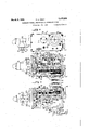
AUXILIARY CONTROL MECHANISM FOR AUTOMATIC PILOT Filed Nov. 20, 1942 55heets-Sheet 2 1 O 4* ==.-.'=az'- 9 I /7z "/50 I73, [92 g 20/ -/5/ 07 O o 200 0 Q AS 204, B
0 w an /l/ INVENTOR ATTORNEY March 9, 1948. P. G. HOLT 2,437,256
AUXILIA RY CONi'ROL. MECHANISM FOR AUTOMATIC PILOT Fil ed Nov. 20, 1942 5' ShegtS-Sheet 3 V 51in E1. UPC, w 7 9 +12 March 9, 1948. HOLT 2,437,256
AUXILIARY CONTROL MECHANISM FOR AUTOMATIC PILOT Filed Nov. 20, 1942 5 Shuts-Sheet 5 muff/u 155 /5/ mvem'on PatentedMar. 9, 1948" AUXILIARY CONTROL MECHANISM FOR AUTOMATIC PILOT I Pliny G. Holt, United States Navy Application November 20,1942, Serial No. 466,301 (01. 244-76) 4 (Granted under the act of March 3, 1883, as
7 Claims.
amended April 30, 1928; 370 0. G. 157) The invention relates to improvements in auto- -matic pilots for aircraft and, more particularly,
to auxiliary control mechanism for use with is automatic pilots of the general character shown if: and described in my copending U. S. patent application Serial No. 442,728, filed May 12,1942, now 'Patent No. 2,401,354, granted June 4, 1946.
An important object of the present invention is to provide an automatic gyro-pilot having auxiliary rudder control mechanism,
Another object of the invention is to provide an automatic gyro-pilot for bomber aircraft having auxiliary rudder control mechanism associated with the bombsight.
Yet another object is the provision of an auto,- matic gyro-pilot with' rudder control mechanism including follow-up means transmitting motion in varying ratios depending on the rudder displacement.
A further object is to provide an automatic gyro-pilot having rudder control mechanism including an adjustable lost-motion follow-up connection.
A still further object is the provision of an automatic gyro-pilot having rudder control mechanism including a resilient follow-up connection.
The invention also aims to provide an automatic gyro-pilot for bombers including auxiliary rudder control mechanism operable by changes in the direction setting of the bombsight.
The invention further aims to provide an automatic gyro-pilot for bombers including auxiliary rudder control mechanism of the character described and provided with-manually operable adjusting means.
Other objects and advantages of the invention will become apparent during the course of the following detailed description, taken in connection with the accompanying drawings, forming a part of this specification, and in which drawings,
Figure 1 is a diagrammatic perspective view of a gyro-pilot provided with the auxiliary rudder control mechanism and showing the servo cable connections to the aircraft control surfaces.
Figure 2 is a view in side elevation of the rudder control unit.
Figure 3 is a top plan view of the rudder control unit, its top cover plate having been removed.
Figure 4 is a bottom plan view of he rudder controlunit, its bottom cover plate having been er/sev Figure 5 is a vertical transverse sectional view of therudder control unit substantially on the line 5-5 ofFigure 3.
Figure 6 is a fragmentary vertical longitudinalsectional detail view substantially on the line 6-6 of Figure 5.
Figure '7 is a viewpartly in top plan and partly .in horizontal section substantially on the line 1-1 of Figure 6 and showing details of a movable control member forming part of the invention.
Figures 8 and-9 are vertical longitudinal sectional detail views substantially on the lines 8-8 and 99, respectively, of Figure 5.
Figure 10 is a fragmentary horizontal sectional view substantially on the 1ine lli--i0 of Figure 2.
Figure 11 is a longitudinal vertical sectional view substantially on the line lill of Figure 10 and showing motion transmitting means including a resilient lost-motion connection disposed in a centered position.
Figure 12 is a view'similar to Figure 11 but showing the relationship of parts upon disposition of the lost-motion connection in an extreme position.
In the drawings, which for the purpose of illustration show only a preferred embodiment of the invention, and wherein similar reference characters designate corresponding parts throughout the several views, the letter A generally designates a conventional gyro-pilot'provided with a bank and climb proportioning unit B and an auxiliary rudder control unit C.
In the example shown, the gyro-pilot A is of the general character shown and described in U. S. Patent No, 1,992,970, granted to Sperry, Jr., et al., and includes a rudder servo control unit 20 having a conventional oil valve 2| for controlling the fiow of oil through pressure and exhaust conduits 2 la, 2!!) to the rudder servomotor 22, and an aileron and elevator servo control unit 23 hydraulically connected, as by suitable conduits 24, 25 to the aileron servomotor 26 and elevator servomotor 27, respectively. The rudder,
. aileron and elevator servomotors 22, 26, 21 are connected, as by suitable cables 28, 29, 30 to the rudder, aileron and elevator surfaces 3!, 32, 33, respectively. These servomotors may be provided with a common shaft 34 rotatable, as bya hand lever 35, to a position wherein the servomotors are by-passed for manual control.
Attached to the servo control units 20, 23 is a bank ,and climb proportioning unit B, such as shown and described in my copending U. S. patent application, Serial No. 442,728 filed May 12, 1942. This bank and climb proportioning unit B includes rudder, aileron and elevator follow-up pulleys 36, 31, 38, provided with follow-up conlectively control the rudder servomotor 22, a-
Referring now to the auxiliary rudder control unit C, the same includes a rectangular box-like housi g 58 having top and bottom cover plates 5 I, 52. Extending through the rear wall 53 of the housingis a valve stem 56 connecting the oil valve 42 with a conventional air relay 51 including opposite outlet ports 59, 68. These ports communicate through cover plates BI, 62 with tubes 63, 64 connected, as by a manifold block 65, with a nipple 66 threaded for attachment to any suitable suction line (not shown). Connected to the air relay 51 at its air inlet nipples 61, 68 are tubes 69, 18 attached, as shown more particularly in Figure 7, to nipples 1|, 12 threaded into one end of a rectangular block 13. Communicating with the nipples 1|, 12 are longitudinal bores 14, 15, intersected by transverse bores 16, 11 having their outer ends sealed as by plugs 18. Extending downwardly from the plane upper surface 19 of the block are spaced transverse series of vertical bores 88, 8| communicating with the transverse bores 16, 11, respectively. Formed in the lower surface of the block 13 are parallel longitudinal grooves 82, 83, within which are securely pressed elongate hardened guide bars 84, 85 provided in their lower exposed faces with V- shaped grooves 86, 81.
Fixed to and extending along one side of the housing 58 is a horizontal interior shelf 98 provided in its upper face with parallel longitudinal grooves 9|, 92. Rigidly fixed in the groove 9I, as by screws 93, is a hardened elongate guide bar 94 provided in its upper exposed face with a V- shaped groove 95. Loosely fitting within the groove 92 is an elongate hardened bar 96 of rectangular shape in cross section and providing a plane upper surface 91. Threaded into the lower surface of the bar 96 are cap screws 98 whose shanks extend loosely through openings 99 in the shelf and whose heads I88 are of a size to prevent passage of the screws 98 through the openings 99. Threaded upwardly through the shelf 98 are set screws I8| engaging the inner face of thebar 96 to adjustably limit movement of the bar inwardly of the groove 92.
Disposed between the grooved bars 84, 95 and between the grooved and ungrooved bars 85, 96 are balls I82 held in spaced relation by suitable elongate retainers I83.
Formed in the upper surface of the block 13 are parallel longitudinal grooves I84, I85, within which are securely pressed elongate hardened guide bars I86, I81, provided in their upper exposed faces with V-shaped grooves I88, I89. Superimposed on the block 13 is a block I I8 provided in its lower surface with parallel longitudinal grooves III, II2. Loosely fitting within the groove III is an' elongate hardened bar II3 provided in its lower exposed face with a V-shaped groove II4. Threaded into the upper surface of the bar II3 are cap screws II4 whose shanks extend loosely through openings H5 in the block H8 and whose heads II6 are of a size to prevent passage of the screws II4 through the openings II5. Threaded downwardly through the block II8 are set screws II1 engaging the inner face of the bar II3 to adjustably limit movement of the bar inwardly of the groove III. Loosely fitting within the groove 2 is an elongate hardened bar I I8 of rectangular shape in cross section and providing a plane lower surface II9. Threaded into the upper surface of the bar II8 are cap screws I28 whose shanks extend loosely through openings I2I in the block I I8 and Whose heads I22 are of a size to prevent passage of the screws I28 through the openings I2I. Threaded downwardly through the block I I8 is a set screw I23 engaging the inner face of the bar II8 to adjustably limit movement of the bar inwardly of the groove II2. bars I86, I I3 and the grooved and ungrooved bars I81, II8 are balls I24 held in spaced relation by suitable elongate retainers I25. Between the blocks 13 and H8 there may be provided a thin coat of oil and when the blocks 13 and H8 are adjusted by the set screws II1 and I23 a clearance is provided between the blocks 13 and H8, the thin coat of oil between the surfaces of the blocks serving as a pneumatic seal. As shown more particularly in Figure 6, the opposite ends of the block II8 are beveled to provide transverse knife edges I26, I21 which are so spaced as to cut the centers of the bores 88, 8| when the blocks 13, H8 arein a neutral relationship. Pivoted for swinging movement about a horizontal axis, as by a pin I38, is an arm |3| carrying a roller I32 urged intoengagement with the upper surface of the block II8, as by a contractile coil spring I33 extending between the free, end portion of the arm I3I and the shelf 98. Fixed above the free end portion of the arm I3I is a bracket I34 provided with a set screw I35 adjustably limiting upward swinging of the arm I3I. Projecting downwardly from the arm .I3I is a pin I36 limiting movement of the lock I I8. Fixed to one side of the block 13 is a plate I31 including spaced upright projections I38 cooperating with spaced pins I39 in the block Hi! to limit relative movement of the blocks 13, I I8.
Means is provided for moving the block I I8 relative to the block 13. Fixed on the block I I8, as by screws I48, isa rectangular perch I4I supporting a square button I42 that pivots about a vertical pin I43 in the perch. Straddling opposite sides of the button I42 are fingers I44 of a :fork I45 releasably connected, as by a bolt I46, to
an arm I41, This arm I41 forms part of an instrument such as a bombsight I48 and is arranged to swing in accordance with changes in the direction setting of the instrument.
Means is also provided for moving the block 13 relative to the block II8. Supported within the housing 58, as by spacer rods I58, is a frame Disposed between the groovedv I62 connected to the rudder servomotor 22, as
shown in Figure .1, by a rudder follow-up cable I63. Connected between the follow-up pulley urging the follow-up pulley to rotate in a clockwise direction as viewed in Figure 2. Fired on the shaft I53 as by a pin I66 is a spur gear I61 meshing with one gear I68 of a pair of intermeshing differential gears I68, I69, carried by the worm wheel, the other gear I68 meshing with aspur gear I10 fastened, as by a pin "I, to a toothed drum I12 rotatable on the shaft I53. Meshing with the toothed drum I12 is asimilar toothed drum I13 rotatable on a shaft I14 and urged in a clockwise direction, as by a spiral spring I15 connected between the drum hub I16 and an anchor post I11; .Returning now to the drum I12, rotatable on its hub I18 is a dog I19 having'opposite fingers I80, I8I. Extending between a pin I82 carried by the finger I80 and a pin I83 carried by the drum I12 is a spiral spring I84 resisting clockwise rotation of the dog I19 relative to the drum. Rotatable on. the hub I18 is a dog I85 having a finger I86. Extending between a pin I81 carried by the finger I86 and the drum hub I18 is a spiral spring I88 resisting counterclockwise rotation of the dog I85 relative to the drum. Welded to the opposite fingers I80, I8I of the dog I19 is an annular concentric partition I89 separating the springs I84, I88. Disposed between the fingers I80, I86 is a pin I carried by the drum I12, and a pin I9I carried by a disc I92 rotatable on the shaft I53. Fixed -to the hub I93 of the disc I92 is a crank arm I94 provided with a longitudinal slot I95 through which extends an adjustable crank pin I96. En-' circling the pin I96 is a washer I91 brought into clamping engagement with the crank arm I94 as by a nut I98 and sleeve I99. Fixed to a rockshaft 260 is a crank arm 20I provided with a longitudinal slot 202 through which the crank pin sleeve I99 extends. Secured to the frame member II are pins 203, 204 limiting swinging movement of the crank arm 20I beyondpredetermined spaced positions." Fixed on the rockshaft 200 is a sector 51 are subjected to equal suction through the nipple 66 and tubes 63, 64, and are equally vented through the tubes 69, 10, longitudinal bores 14,
15, tranverse bores 16, 11, and vertical bores 80, 8|, when the blocks 13, H0 are disposed in centered or neutral relationship, as shown in Figure 6. Upon the occurrence of a change in the direction setting of the bombsight or other instrument I48, the arm I41 thereof will swing so that the fork I45 shifts the block III) in a direction relative to the block 13 depending on the direction of change in the setting of the bombslght or other instrument I48. This movement of the block IIO relative to the block 13 will displace the knife edges I26, I21, so as to .close one of the bores 80, 8| while opening the other. The
I62 and an anchor post I64 is a spiral spring I65 resulting difference in pressure between opposite sides of the air relay 51 imparts movement to the oil valve 42 through the .stem56, whereby the rudder servo 22 is actuated in a direction depending on the direction of change in the setting of the bombsight or other instrument. From the rudder servo 22 movement is transmitted to the follow-up pulley I62 and shaft I53 via the followup connection I63. Rotation of the shaft I53 imparts opposite rotation to the toothed drum I12 via sector gear I61, differential gears I68, I69, and sector gear I10. Clockwise or counterclockwise rotation of the drum I12 is transmitted to the disc I92 via the spring I84 or spring I88, respectively, dog I19 or dog I85, respectively, and pin I9I, to swing the crank 'arm I94 from the c'entered positionshown in Figure 11. At first,
. the entire motion of the arm I94 lstransmitted through the crank pin I96, to the arm 20I, but
in moving in either direction away from its centered position, an increasing amount of slippage occurs between the crank pin I96 and the arm at slot 202, whereby the ratio of motion transmission between the arms I94 and 20I decreases as the arm I94 swings away from its neutral position. Through the rockshaft 200, movement of the arm 20I is transmitted to the sector 205 so as to shift the block 13 relative to the block H0, the follow-up movement of the block 13 being in the same direction as the instrument-controlled movement of the block I I0, whereby the bores 80, 81 are again brought into alignment with the knife edges I26, I21. Thus, the air relay 51 and oil valve 42 are recentered, and further movement of the rudder servomotor 22 away from neutral is prevented. It will, of course, be understood that as the aircraft turns toward the direction gear 205 extending througha slot 206 in the shelf 90, as shown in Figure 6, and meshing with of travel in order to satisfy the instrument I48, the arm I41 thereof will commence retracting the block I I0 to its original position, and the rudder servomotor is moved toward its neutral position.
Upon predetermined rotation of the rudder follow-up shaft I53, the crank arm 20I engages one of the stops 203, 204, as shown in Figure 12, whereby further. movement of the disc I92 is prevented. Additional movement of the follow-up shaft will thereupon rotate the toothed drum I12 relative to the disc I92, against the resistance of the springs I84, I88, until limited by engagement of the dog I19 and one of thepins I90, I9I. In Figure 12, the pin I90 carried by the toothed drum is shown in engagement with finger I8I of the dog I19, the opposite finger I of the do abutting the pin I9I carried by the disc. The spring I15 exerts a counterclockwise bias on the toothed drum I12. It will thus be seen that a resilient lost motion connection and a variable ratio motion transmission are provided between the follow-up shaft I53 and the rock shaft 200. By manipulating the control knob I58, the worm I59 and worm wheel I54 may be turned, for
' transmitting motion, through the differential gears I68, I69, and the sector gear I10, to the' toothed drum I12. This arrangement permits fiigustmentof the block I01 relative to the block Various changes may be made in the form of invention herein shown and described without departing from the spirit of the invention or the scope of the following claims.
The invention described herein may be 'manufactured and/or used by or for the Government of the United States of America for governmental purposes without the payment of any royalties thereon or therefor.
What I claim is:
1. In an automatic pilot bomber for aircraft, a rudder operating means, an aileron operating means, a gyroscopic means for controlling said rudderoperating means, a gyroscopic means for controlling said aileron operating means, a follow-up connection between said rudder operatin means and said rudder controlling gyroscopic meansjmeans responsive to operation of said rudder operating means for influencing said aileron controlling means whereby the amount of bank is correlated with the rudder displacement of the aircraft, an auxiliary mechanism for controlling said rudder operating means, a followup connection between said rudder operating means and said auxiliary mechanism, a bombsight, means connecting said auxiliary mechanism to said bombsight, said auxiliary mechanism, rudder operating means and g-yroscopic rudder control means responsive to changes in the direction setting of said bombsight.
2. In an automatic pilot for aircraft, a rudder operating means, a rudder control mechanism including first and second members relatively movable for controlling the rudder operating means, a movable means for moving said first member relative to said second member, a rudder followup means connected to said second member, a resilient lost-motion connection between said second means and said follow-up means, said follow-up means so constructed and arranged to transmit motion from the rudder operating means to the second member at varying ratios depending on the position of the rudder operating means.
3. In an automatic pilot for aircraft, a rudder operating means, a rudder control mechanism including first and second members relativelymovable for controlling the rudder operating means, movable means for moving the first member relative to the second member, a rudder follow-up means for moving the second member relative to the first member, a resilient lost-motion connection between said second member and said follow-up means, said follow-up means including driving and driven members, and means connecting the driving and driven members whereby movement of the driving member transmits motion in varying ratios to the driven member.
4. In an automatic aircraft pilot, a rudder operating means, an auxiliary mechanism connected to said rudder operating means including a. rudder control mechanism having first and second members relatively movable for controlling the rudder operating means, movable means for moving the first member relative to the second member, a rudder follow-up means for moving the second member relative to the first, said follow-up means including a drive shaft provided with an arm, a driven shaft provided with an arm, a pin adjustably fixed to the drive shaft arm and slidably connected to the driven shaft arm, whereby movement of said drive shaft is transmitted in varying ratios to the driven shaft, and a resilient connection between said movable means and said follow-up means.
5. Auxiliary control mechanism for use with an aircraft gyro-pilot, said gyro-pilot comprising Number means for moving the first member relative to the second member, rudder follow-up means connected to said second member and including a lost-motion connection and a resilient connec-v tion, said follow-up means having means for transmitting motion to said second member at varying ratios depending on the position of the rudder operating means.
6. Auxiliary control mechanism for use with an aircraft gyro-pilot, said gyro-pilot comprising rudder operating means and gyroscopic control means for the rudder operating means, said auxiliary control mechanism comprising first and second members movable for controlling the rudder operating means, instrument controlled means interconnected with said first member for moving the first member relative to the second member, rudder follow-up means including a lost-motion connection and mechanism for transmitting motion to said second member at varying ratios depending on the position of the rudder operating means, said follow-up means including a differential, and means operating through said differential for manually adjusting the first member relative to the second.
7. Auxiliary control mechanism for use with an aircraft gyro-pilot having a rudder operating means, said auxiliary control mechanism comprising first and second members relatively movable for controlling the rudder operating means, means for moving the first member relative to the second member, rudder follow-up means for moving the second member relative to the first member including interconnected driving and driven elements, said driven member responsive REFERENCES crisp The following references are of record in the file of this patent:
UNITED STATES PATENTS Name Date 1,880,671 Bates Oct. 4, 1932 1,896,805 Sperry et a1. Feb. 7. 1933 1,919,191 Bates July 25, 1933 1,958,259 Becker May 8, 1934 1,992,970 Sperry et a1 Mar. 5, 1935 2,091,306 Carlson;- Aug. 31, 1937 2,143,140 Carlson Jan. 10, 1939 2,191,250 Fischel" Feb. 20, 1940 2,201,174 Harding et a1. May 21, 1940 2,283,754 Matthews May 19, 1942 2,327,171 Carlson Aug. 17, 1943 2,346,857 Meredith Apr. 18, 1944 I FOREIGN PATENTS Number Country Date 260,260 Great Britain Jan. 12, 1928
Priority Applications (1)
| Application Number | Priority Date | Filing Date | Title |
|---|---|---|---|
| US466301A US2437256A (en) | 1942-11-20 | 1942-11-20 | Auxiliary control mechanism for automatic pilot |
Applications Claiming Priority (1)
| Application Number | Priority Date | Filing Date | Title |
|---|---|---|---|
| US466301A US2437256A (en) | 1942-11-20 | 1942-11-20 | Auxiliary control mechanism for automatic pilot |
Publications (1)
| Publication Number | Publication Date |
|---|---|
| US2437256A true US2437256A (en) | 1948-03-09 |
Family
ID=23851246
Family Applications (1)
| Application Number | Title | Priority Date | Filing Date |
|---|---|---|---|
| US466301A Expired - Lifetime US2437256A (en) | 1942-11-20 | 1942-11-20 | Auxiliary control mechanism for automatic pilot |
Country Status (1)
| Country | Link |
|---|---|
| US (1) | US2437256A (en) |
Cited By (1)
| Publication number | Priority date | Publication date | Assignee | Title |
|---|---|---|---|---|
| US2704646A (en) * | 1955-03-22 | vogel |
Citations (13)
| Publication number | Priority date | Publication date | Assignee | Title |
|---|---|---|---|---|
| GB260260A (en) * | 1925-10-24 | 1928-01-12 | Maurice Alexandre Mazade | Improvements in stabilizing apparatus for aircraft and vessels |
| US1880671A (en) * | 1929-10-18 | 1932-10-04 | Sperry Gyroscope Co Inc | Bomb sight alignment and rudder control |
| US1896805A (en) * | 1930-02-20 | 1933-02-07 | Sperry Gyroscope Co Inc | Directional radio steering device |
| US1919191A (en) * | 1931-07-18 | 1933-07-25 | Sperry Gyroscope Co Inc | Bomb sight and pilot director |
| US1958259A (en) * | 1931-08-12 | 1934-05-08 | Gen Electric | Automatic steering equipment |
| US1992970A (en) * | 1932-09-02 | 1935-03-05 | Sperry Gyroscope Co Inc | Hydropneumatic automatic pilot |
| US2091306A (en) * | 1936-06-12 | 1937-08-31 | Sperry Gyroscope Co Inc | Level flight control for automatic pilots |
| US2143140A (en) * | 1936-10-23 | 1939-01-10 | Sperry Gyroscope Co Inc | Altitude control for aircraft |
| US2191250A (en) * | 1934-09-24 | 1940-02-20 | Siemens App Und Maschinen Gmbh | System for the automatic control of airplanes |
| US2201174A (en) * | 1937-07-03 | 1940-05-21 | Sperry Gyroscope Co Inc | Automatic steering system for aircraft |
| US2283754A (en) * | 1939-04-08 | 1942-05-19 | Sperry Gyroscope Co Inc | Automatic banking means for airplane gyro pilots |
| US2327171A (en) * | 1942-04-13 | 1943-08-17 | Jack & Heintz Inc | Aircraft control device |
| US2346857A (en) * | 1940-01-05 | 1944-04-18 | Smith & Sons Ltd S | Fluid-actuated servomotor system |
-
1942
- 1942-11-20 US US466301A patent/US2437256A/en not_active Expired - Lifetime
Patent Citations (13)
| Publication number | Priority date | Publication date | Assignee | Title |
|---|---|---|---|---|
| GB260260A (en) * | 1925-10-24 | 1928-01-12 | Maurice Alexandre Mazade | Improvements in stabilizing apparatus for aircraft and vessels |
| US1880671A (en) * | 1929-10-18 | 1932-10-04 | Sperry Gyroscope Co Inc | Bomb sight alignment and rudder control |
| US1896805A (en) * | 1930-02-20 | 1933-02-07 | Sperry Gyroscope Co Inc | Directional radio steering device |
| US1919191A (en) * | 1931-07-18 | 1933-07-25 | Sperry Gyroscope Co Inc | Bomb sight and pilot director |
| US1958259A (en) * | 1931-08-12 | 1934-05-08 | Gen Electric | Automatic steering equipment |
| US1992970A (en) * | 1932-09-02 | 1935-03-05 | Sperry Gyroscope Co Inc | Hydropneumatic automatic pilot |
| US2191250A (en) * | 1934-09-24 | 1940-02-20 | Siemens App Und Maschinen Gmbh | System for the automatic control of airplanes |
| US2091306A (en) * | 1936-06-12 | 1937-08-31 | Sperry Gyroscope Co Inc | Level flight control for automatic pilots |
| US2143140A (en) * | 1936-10-23 | 1939-01-10 | Sperry Gyroscope Co Inc | Altitude control for aircraft |
| US2201174A (en) * | 1937-07-03 | 1940-05-21 | Sperry Gyroscope Co Inc | Automatic steering system for aircraft |
| US2283754A (en) * | 1939-04-08 | 1942-05-19 | Sperry Gyroscope Co Inc | Automatic banking means for airplane gyro pilots |
| US2346857A (en) * | 1940-01-05 | 1944-04-18 | Smith & Sons Ltd S | Fluid-actuated servomotor system |
| US2327171A (en) * | 1942-04-13 | 1943-08-17 | Jack & Heintz Inc | Aircraft control device |
Cited By (1)
| Publication number | Priority date | Publication date | Assignee | Title |
|---|---|---|---|---|
| US2704646A (en) * | 1955-03-22 | vogel |
Similar Documents
| Publication | Publication Date | Title |
|---|---|---|
| US2144616A (en) | Remote control means for airplane automatic pilots | |
| US2575792A (en) | Control mechanism | |
| US2143139A (en) | Hydraulic automatic pilot | |
| US1612118A (en) | Control system for ordnance | |
| US2548481A (en) | Flying control for aircraft | |
| US2717652A (en) | Hydraulic pitch control system | |
| US2437256A (en) | Auxiliary control mechanism for automatic pilot | |
| US2284298A (en) | Servo system for airplanes and other vehicles | |
| US2664960A (en) | Topping governor and reversing solenoid for variable pitch propellers | |
| US2664959A (en) | Aircraft engine and propeller control system | |
| US2210917A (en) | Reactive servo system for automatic pilots | |
| US2940332A (en) | Ratio changer device | |
| US2466041A (en) | Servo system and control thereof | |
| US2049375A (en) | Automatic steering control | |
| US2410097A (en) | Glide attachment for bomb sights | |
| US3286958A (en) | Co-pilot navigation control | |
| US2204290A (en) | Automatic steering device | |
| US2425433A (en) | Control mechanism for gun training apparatus | |
| US2406374A (en) | Differential rudder lever control | |
| US3295386A (en) | Three-axis controller | |
| US2468635A (en) | Apparatus for testing hydraulic and electric propeller governors | |
| US2369456A (en) | Steering mechanism for vessels | |
| US2036914A (en) | Gyroscopic apparatus | |
| US2333605A (en) | Apparatus for use in fire control of antiaircraft guns | |
| US2401354A (en) | Automatic pilot for aircraft |