US2460314A - Apparatus for supervising heat generating means - Google Patents
Apparatus for supervising heat generating means Download PDFInfo
- Publication number
- US2460314A US2460314A US526637A US52663744A US2460314A US 2460314 A US2460314 A US 2460314A US 526637 A US526637 A US 526637A US 52663744 A US52663744 A US 52663744A US 2460314 A US2460314 A US 2460314A
- Authority
- US
- United States
- Prior art keywords
- supervising
- radiator
- generating means
- heat generating
- flame
- Prior art date
- Legal status (The legal status is an assumption and is not a legal conclusion. Google has not performed a legal analysis and makes no representation as to the accuracy of the status listed.)
- Expired - Lifetime
Links
- 230000005855 radiation Effects 0.000 description 6
- 238000010438 heat treatment Methods 0.000 description 4
- 239000000446 fuel Substances 0.000 description 3
- 239000010453 quartz Substances 0.000 description 3
- VYPSYNLAJGMNEJ-UHFFFAOYSA-N silicon dioxide Inorganic materials O=[Si]=O VYPSYNLAJGMNEJ-UHFFFAOYSA-N 0.000 description 3
- 230000003321 amplification Effects 0.000 description 2
- 238000001816 cooling Methods 0.000 description 2
- 238000003199 nucleic acid amplification method Methods 0.000 description 2
- BASFCYQUMIYNBI-UHFFFAOYSA-N platinum Chemical compound [Pt] BASFCYQUMIYNBI-UHFFFAOYSA-N 0.000 description 2
- 230000001681 protective effect Effects 0.000 description 2
- 241000354018 Catamixis Species 0.000 description 1
- 239000010425 asbestos Substances 0.000 description 1
- 230000008033 biological extinction Effects 0.000 description 1
- 238000002485 combustion reaction Methods 0.000 description 1
- 230000000694 effects Effects 0.000 description 1
- 238000002474 experimental method Methods 0.000 description 1
- 238000004880 explosion Methods 0.000 description 1
- 230000002349 favourable effect Effects 0.000 description 1
- 239000002737 fuel gas Substances 0.000 description 1
- 238000009434 installation Methods 0.000 description 1
- 239000000463 material Substances 0.000 description 1
- 238000012986 modification Methods 0.000 description 1
- 230000004048 modification Effects 0.000 description 1
- 229910052697 platinum Inorganic materials 0.000 description 1
- 229910052895 riebeckite Inorganic materials 0.000 description 1
- 230000035945 sensitivity Effects 0.000 description 1
- WFKWXMTUELFFGS-UHFFFAOYSA-N tungsten Chemical compound [W] WFKWXMTUELFFGS-UHFFFAOYSA-N 0.000 description 1
- 229910052721 tungsten Inorganic materials 0.000 description 1
- 239000010937 tungsten Substances 0.000 description 1
- 238000001429 visible spectrum Methods 0.000 description 1
Images
Classifications
-
- F—MECHANICAL ENGINEERING; LIGHTING; HEATING; WEAPONS; BLASTING
- F23—COMBUSTION APPARATUS; COMBUSTION PROCESSES
- F23N—REGULATING OR CONTROLLING COMBUSTION
- F23N5/00—Systems for controlling combustion
- F23N5/02—Systems for controlling combustion using devices responsive to thermal changes or to thermal expansion of a medium
- F23N5/08—Systems for controlling combustion using devices responsive to thermal changes or to thermal expansion of a medium using light-sensitive elements
- F23N5/085—Systems for controlling combustion using devices responsive to thermal changes or to thermal expansion of a medium using light-sensitive elements using electrical or electromechanical means
-
- F—MECHANICAL ENGINEERING; LIGHTING; HEATING; WEAPONS; BLASTING
- F27—FURNACES; KILNS; OVENS; RETORTS
- F27B—FURNACES, KILNS, OVENS OR RETORTS IN GENERAL; OPEN SINTERING OR LIKE APPARATUS
- F27B7/00—Rotary-drum furnaces, i.e. horizontal or slightly inclined
- F27B7/20—Details, accessories or equipment specially adapted for rotary-drum furnaces
-
- F—MECHANICAL ENGINEERING; LIGHTING; HEATING; WEAPONS; BLASTING
- F23—COMBUSTION APPARATUS; COMBUSTION PROCESSES
- F23N—REGULATING OR CONTROLLING COMBUSTION
- F23N5/00—Systems for controlling combustion
- F23N5/02—Systems for controlling combustion using devices responsive to thermal changes or to thermal expansion of a medium
- F23N5/08—Systems for controlling combustion using devices responsive to thermal changes or to thermal expansion of a medium using light-sensitive elements
Definitions
- the invention also provides for amplification; of photoelectrically eflectlve radiant energy generally and in still another aspect it provides a very simple and reliable way oven control installation incorporating the invention;
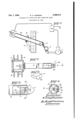
- Fig. 2 a side view, with the tube ends in section, of the observation unit shown in Fig. 1;
- Fig. 3 a section on line 3-3 of Fig. 2; Fig. 4 a sec iio'npn line 4-4 of Fig. 3; and
- Fig. 5 an a on'ometric view of the holding block shown in Figs. 2' to 4.
- Fig. l which shows the general arrangement of a practical embodiment of the invention
- -numeral i represents the wall or other enclosure element of an oven or furnace
- 2 the fuel gas supply duct
- 3 an electrically operated fuel valve
- I a burner tube of the conven-' tional drilled port type using pre-mixed'fuel.
- an auxiliary radiator element 20 which preferably j consists of material capable of emitting when heated to the available temperature, radiation of the frequency to which commercial phototubes are preponderantly sensitive, namely the red to infrared frequency range.
- the radiator element may consist of an emitter element l5 (Figs. 3 and 4), for example. of platinum -or black oxidized tungsten comprising a rectangular strip 7/6 wide and ,5 long of a thickness of approximately .001" fused between two sheets of protective quartz approximately wide and long, the said quartz sheets being approximately .005" thick and comprising the envelope II, the envelope being supported on a rectangularly bent supporting rod 11 of quartz joined to the envelope'ii with a narrow neck which reduces heat conduction.
- emitter element l5 Figs. 3 and 4
- platinum -or black oxidized tungsten comprising a rectangular strip 7/6 wide and ,5 long of a thickness of approximately .001" fused between two sheets of protective quartz approximately wide and long, the said quartz sheets being approximately .005" thick and comprising the envelope II, the envelope being supported on a rectangularly bent supporting rod 11 of quartz joined to the envelope'ii with a narrow neck which reduces heat conduction.
- the radiator element 20 may be supported at the end of an observation tube ll fastened to wall I by means of bracket l9 (Fig. 1) by means of a clamp block 2
- the supporting rod" of the radiator element is held in the slot 22 of clamp block 2
- tube II On either side of radiator element 20, tube II is provided with cut-outs 28, 29 (Figs. 2 and 4) which admit flame l0 and also protect it, thereby reducing flickering.
- a phototube 40 for observing radiator 20.
- the tube may be mounted, with orwithout its amplifying and control circuit elements, in a protective housing it having appropriate provisions for cooling and ventilating the apparatus therewithin; such as slots 32 and flns 33.
- auxiliary radiator 29 may be reduced from the specific disclosure above set forth where conditions are favorable or desirable.
- the mass of the auxiliary radiator is so selected depending upon prevailing temperature conditions and control requirements, preferably by simple experiment employing a series of sample elements of stepped size, that the effect of flame fluctuations within a given maximum duration is eliminated, whereas all, longer fluctuations will cause cooling of element 20 to such-an extent that the phototube becomes unresponsive.
- the phototube impedance is sufficiently reduced to actuate an amplifying and relay circuit indicated at 40 and supplied from a current source 4
- Control valve 3 is thus maintained open so long as flame l burns. tube impedance increases and the control circuit closes valve 3.
- Apparatus for supervising a heat generating means comprising said heat generating means which radiates light of a comparatively low in- Upon extinction of the flame, the phototensity, a light responsive device arranged for supervising said heat generating means, and a body arranged to be heated by said heating means and adapted to radiate light of a comparatively high intensity when heated by said heating means, the said body comprising an incandescible member imbedded in a transparent heat conducting envelope located in said energy source.
- a flame supervising apparatus having a heat source and a light responsive device for the purpose of supervising said energy source, an improved light radiator interposed between said heat source and said light responsive device for the purpose of supervising said heat source, said light radiator comprising an incandescible member contained in a transparent envelope which envelope is located in said heat source, and adapted to become incandescent only when said heat source is emitting heat.
- An improved light radiator in combination with a heat source.
- said radiator comprising an incandescible element sealed in a transparent envelope, the said element becoming incandescent only when said heat source is emitting, said heat source being external to said envelope in heat transfer relation therewith.
- An improved light radiator in combination with a heat source, said radiator comprising an incandescible element sealed in a transparent fused envelope, the said element becoming incandescent only when said heat source is emitting, said heat source being external to said envelope in heat transfer relation therewith.
Landscapes
- Engineering & Computer Science (AREA)
- Mechanical Engineering (AREA)
- General Engineering & Computer Science (AREA)
- Chemical & Material Sciences (AREA)
- Combustion & Propulsion (AREA)
- Photometry And Measurement Of Optical Pulse Characteristics (AREA)
Description
Feb. 1 1949. Q E. c. THOMSON 2,460,314
APPARATUS FOR SUPERVISING HEAT GENERATING MEANS Filed March 15. L944 177 VB 7710 r' E. E'Psig Thnmsnn fiDT'TI By meme Feb. 1, 1949 UNITED srArEs E fr FF E A 2,400,311
APPARATUS FOR SUPEBVISING HEAT GENERATING MEANS s. cm; Thomson, Boston, Mala, namito Combustion Control Corporation,.0ambridgc, Mass.) a corporation of Massachusetts Application March 15, is. sunrise. 52am '5 Claims. (cuss-117.1)
practical phototubes are primarily sensitive, i
namely the highest wave length region of the visible spectrum and the infrared region.
In order to supervise such flames with red and infrared sensitive phototubes it was heretofore necessary to use high amplification in the photoelectric circuit, which involves the disadvantages of instability and complexity of the control circuit and tends to render the control device unreliable.
It is one of the main objects of the present invention to avoid these disadvantages by introducing a radiation frequency converting link, in the form of an auxiliary radiator, between the; primary radiator which emits little photoelectrically effective radiation, and the detecting phototube.
In another aspect, the invention also provides for amplification; of photoelectrically eflectlve radiant energy generally and in still another aspect it provides a very simple and reliable way oven control installation incorporating the invention;
Fig. 2 a side view, with the tube ends in section, of the observation unit shown in Fig. 1;
Fig. 3 a section on line 3-3 of Fig. 2; Fig. 4 a sec iio'npn line 4-4 of Fig. 3; and
Fig. 5 an a on'ometric view of the holding block shown in Figs. 2' to 4.
In Fig. l, which shows the general arrangement of a practical embodiment of the invention,-numeral i represents the wall or other enclosure element of an oven or furnace, 2 the fuel gas supply duct, 3 an electrically operated fuel valve, and I a burner tube of the conven-' tional drilled port type using pre-mixed'fuel.
an auxiliary radiator element 20 which preferably j consists of material capable of emitting when heated to the available temperature, radiation of the frequency to which commercial phototubes are preponderantly sensitive, namely the red to infrared frequency range.
The radiator element may consist of an emitter element l5 (Figs. 3 and 4), for example. of platinum -or black oxidized tungsten comprising a rectangular strip 7/6 wide and ,5 long of a thickness of approximately .001" fused between two sheets of protective quartz approximately wide and long, the said quartz sheets being approximately .005" thick and comprising the envelope II, the envelope being supported on a rectangularly bent supporting rod 11 of quartz joined to the envelope'ii with a narrow neck which reduces heat conduction. Y
The radiator element 20 may be supported at the end of an observation tube ll fastened to wall I by means of bracket l9 (Fig. 1) by means of a clamp block 2| (Figs. 2 to 5) having a slot 22 and fastened to the end of tube It by means of screws 23. The supporting rod" of the radiator element is held in the slot 22 of clamp block 2| by means of an asbestos lining 24 (Fig. 4).
On either side of radiator element 20, tube II is provided with cut-outs 28, 29 (Figs. 2 and 4) which admit flame l0 and also protect it, thereby reducing flickering.
At the outer end of tube i8 is arranged a phototube 40 for observing radiator 20. The tube may be mounted, with orwithout its amplifying and control circuit elements, in a protective housing it having appropriate provisions for cooling and ventilating the apparatus therewithin; such as slots 32 and flns 33.
The above-described arrangement operates as follows:
The flame it by itself does not radiate sufflcient energy to which phototube 30 is effectively responsive, but retains the emitting element ll incandescent so long as the flame b this element emitting intensive radiation of a wavelength higher than that of the flame with which it is associated, and well within the range of the phototube sensitivity. On the other hand, the
mass of body 20 canv be so dimensioned that rapid fluctuation of the flame such as due to flutter can be renderedharmless by a selected time lag between the flame fluctuation and the corresponding radiation intensity of element ll, whereas the element can be made small enough to eliminate any danger of explosion due to de- Piaced into the hottest portion of flame it is as layed response of the supervising control appa- 3 ratus. The dimensions of the auxiliary radiator 29 may be reduced from the specific disclosure above set forth where conditions are favorable or desirable. In other words, the mass of the auxiliary radiator is so selected depending upon prevailing temperature conditions and control requirements, preferably by simple experiment employing a series of sample elements of stepped size, that the effect of flame fluctuations within a given maximum duration is eliminated, whereas all, longer fluctuations will cause cooling of element 20 to such-an extent that the phototube becomes unresponsive.
With name to burning and auxiliary radiator 20 emitting as-above described, the phototube impedance is sufficiently reduced to actuate an amplifying and relay circuit indicated at 40 and supplied from a current source 4|. Control valve 3 is thus maintained open so long as flame l burns. tube impedance increases and the control circuit closes valve 3.
It will be understood that, instead of the arrangement including tube l8, any structure which provides proper correlation of the primary heater such as flame [0, of the auxiliary radiator and of the phototube may be used.
It will be further. understood that the use of arrangements according to the invention is not restricted to gaseous fuel equipment such as herein shown by way of example, but that it can be advantageously applied to any heating system which provides analogous problems of supervision and control.
It should be understood that the present disclosure is for the purpose of illustration only and that this invention includes all modifications and equivalents which fall within the scope of the appended claims.
I claim:
1. In apparatus for supervising an energy source adapted to radiate predominantly at a certain frequency range, with a radiation responsive device predominantly sensitive to a second frequency range, the combination of said source and said device with an auxiliary radiator comprising an incandescible radiator element siealed within a heat conducting envelope located in said source and adapted to radiate said second range upon being subjected to heating from said source.
2. Apparatus for supervising a heat generating means, comprising said heat generating means which radiates light of a comparatively low in- Upon extinction of the flame, the phototensity, a light responsive device arranged for supervising said heat generating means, and a body arranged to be heated by said heating means and adapted to radiate light of a comparatively high intensity when heated by said heating means, the said body comprising an incandescible member imbedded in a transparent heat conducting envelope located in said energy source.
3. In a flame supervising apparatus having a heat source and a light responsive device for the purpose of supervising said energy source, an improved light radiator interposed between said heat source and said light responsive device for the purpose of supervising said heat source, said light radiator comprising an incandescible member contained in a transparent envelope which envelope is located in said heat source, and adapted to become incandescent only when said heat source is emitting heat.
4. An improved light radiator in combination with a heat source. said radiator comprising an incandescible element sealed in a transparent envelope, the said element becoming incandescent only when said heat source is emitting, said heat source being external to said envelope in heat transfer relation therewith.
5. An improved light radiator in combination with a heat source, said radiator comprising an incandescible element sealed in a transparent fused envelope, the said element becoming incandescent only when said heat source is emitting, said heat source being external to said envelope in heat transfer relation therewith.
- E. CRAIG THOMSON.
REFERENCES CITED The following references are of record in the file of this patent:
UNITED STATES PATENTS
Priority Applications (1)
| Application Number | Priority Date | Filing Date | Title |
|---|---|---|---|
| US526637A US2460314A (en) | 1944-03-15 | 1944-03-15 | Apparatus for supervising heat generating means |
Applications Claiming Priority (1)
| Application Number | Priority Date | Filing Date | Title |
|---|---|---|---|
| US526637A US2460314A (en) | 1944-03-15 | 1944-03-15 | Apparatus for supervising heat generating means |
Publications (1)
| Publication Number | Publication Date |
|---|---|
| US2460314A true US2460314A (en) | 1949-02-01 |
Family
ID=24098130
Family Applications (1)
| Application Number | Title | Priority Date | Filing Date |
|---|---|---|---|
| US526637A Expired - Lifetime US2460314A (en) | 1944-03-15 | 1944-03-15 | Apparatus for supervising heat generating means |
Country Status (1)
| Country | Link |
|---|---|
| US (1) | US2460314A (en) |
Cited By (7)
| Publication number | Priority date | Publication date | Assignee | Title |
|---|---|---|---|---|
| US3064128A (en) * | 1958-10-17 | 1962-11-13 | Honeywell Regulator Co | Measuring apparatus |
| US3091694A (en) * | 1960-03-23 | 1963-05-28 | Freeman Goodridge Ltd | Method and apparatus for measurement of temperature |
| US3906221A (en) * | 1973-12-10 | 1975-09-16 | Gary M Mercier | Proof of igniter and flame sensing device and system |
| US4477245A (en) * | 1982-09-03 | 1984-10-16 | The Babcock & Wilcox Company | Flame monitoring safety, energy and fuel conservation system |
| WO1985000647A1 (en) * | 1983-07-25 | 1985-02-14 | Quantum Group Inc. | Photovoltaic control systems |
| US4898531A (en) * | 1983-07-25 | 1990-02-06 | Quantum Group, Inc. | Photosensitive control of electrically powered emissive ignition devices |
| US4976606A (en) * | 1983-09-02 | 1990-12-11 | Tpv Energy Systems, Inc. | Thermophotovoltaic technology |
Citations (12)
| Publication number | Priority date | Publication date | Assignee | Title |
|---|---|---|---|---|
| US1639534A (en) * | 1921-05-28 | 1927-08-16 | Ruben Samuel | Pyrometer |
| US1659749A (en) * | 1920-12-04 | 1928-02-21 | Gen Electric | Electric incandescent lamp and method of manufacturing its illuminating body |
| US1749136A (en) * | 1916-07-03 | 1930-03-04 | Sirian Lamp Co | Incandescent electric lamp |
| US1906244A (en) * | 1933-05-02 | Combustion contboi | ||
| US1994860A (en) * | 1932-09-01 | 1935-03-19 | Imp Brass Mfg Co | Pilot light |
| US2007714A (en) * | 1933-03-27 | 1935-07-09 | Frank A Gauger | Fluid heater |
| US2122850A (en) * | 1936-09-19 | 1938-07-05 | Gen Electric | Amplifier |
| US2141322A (en) * | 1935-06-25 | 1938-12-27 | Rca Corp | Cascaded secondary electron emitter amplifier |
| US2183717A (en) * | 1936-11-05 | 1939-12-19 | Rca Corp | Modulation control system |
| US2292243A (en) * | 1940-10-01 | 1942-08-04 | Babcock & Wilcox Co | Kiln control |
| US2295045A (en) * | 1939-04-17 | 1942-09-08 | Hal C Mettler | Safety pilot for furnaces |
| US2306073A (en) * | 1939-12-08 | 1942-12-22 | Photoswitch Inc | Photoelectric control of heating equipment |
-
1944
- 1944-03-15 US US526637A patent/US2460314A/en not_active Expired - Lifetime
Patent Citations (12)
| Publication number | Priority date | Publication date | Assignee | Title |
|---|---|---|---|---|
| US1906244A (en) * | 1933-05-02 | Combustion contboi | ||
| US1749136A (en) * | 1916-07-03 | 1930-03-04 | Sirian Lamp Co | Incandescent electric lamp |
| US1659749A (en) * | 1920-12-04 | 1928-02-21 | Gen Electric | Electric incandescent lamp and method of manufacturing its illuminating body |
| US1639534A (en) * | 1921-05-28 | 1927-08-16 | Ruben Samuel | Pyrometer |
| US1994860A (en) * | 1932-09-01 | 1935-03-19 | Imp Brass Mfg Co | Pilot light |
| US2007714A (en) * | 1933-03-27 | 1935-07-09 | Frank A Gauger | Fluid heater |
| US2141322A (en) * | 1935-06-25 | 1938-12-27 | Rca Corp | Cascaded secondary electron emitter amplifier |
| US2122850A (en) * | 1936-09-19 | 1938-07-05 | Gen Electric | Amplifier |
| US2183717A (en) * | 1936-11-05 | 1939-12-19 | Rca Corp | Modulation control system |
| US2295045A (en) * | 1939-04-17 | 1942-09-08 | Hal C Mettler | Safety pilot for furnaces |
| US2306073A (en) * | 1939-12-08 | 1942-12-22 | Photoswitch Inc | Photoelectric control of heating equipment |
| US2292243A (en) * | 1940-10-01 | 1942-08-04 | Babcock & Wilcox Co | Kiln control |
Cited By (7)
| Publication number | Priority date | Publication date | Assignee | Title |
|---|---|---|---|---|
| US3064128A (en) * | 1958-10-17 | 1962-11-13 | Honeywell Regulator Co | Measuring apparatus |
| US3091694A (en) * | 1960-03-23 | 1963-05-28 | Freeman Goodridge Ltd | Method and apparatus for measurement of temperature |
| US3906221A (en) * | 1973-12-10 | 1975-09-16 | Gary M Mercier | Proof of igniter and flame sensing device and system |
| US4477245A (en) * | 1982-09-03 | 1984-10-16 | The Babcock & Wilcox Company | Flame monitoring safety, energy and fuel conservation system |
| WO1985000647A1 (en) * | 1983-07-25 | 1985-02-14 | Quantum Group Inc. | Photovoltaic control systems |
| US4898531A (en) * | 1983-07-25 | 1990-02-06 | Quantum Group, Inc. | Photosensitive control of electrically powered emissive ignition devices |
| US4976606A (en) * | 1983-09-02 | 1990-12-11 | Tpv Energy Systems, Inc. | Thermophotovoltaic technology |
Similar Documents
| Publication | Publication Date | Title |
|---|---|---|
| US2306073A (en) | Photoelectric control of heating equipment | |
| US2304641A (en) | Control apparatus | |
| US2811856A (en) | Temperature measuring apparatus | |
| US2460314A (en) | Apparatus for supervising heat generating means | |
| JPH0369150B2 (en) | ||
| US2295045A (en) | Safety pilot for furnaces | |
| GB1008941A (en) | Flame monitor | |
| US2418845A (en) | Optical safety device | |
| US2361530A (en) | Control system for ovens | |
| US4001633A (en) | Device provided with a gas and/or vapor discharge tube | |
| US4207053A (en) | Igniter and flame sensor assembly for gas burning appliance | |
| US2305585A (en) | Thermocouple and pilot burner | |
| US2544930A (en) | Pilot burner and flame detector assembly | |
| US3076495A (en) | Fuel burning and flame detection means | |
| US2610677A (en) | Fuel burner safety control apparatus | |
| GB988297A (en) | Combination pilot burner and flame detector unit | |
| US2441672A (en) | Thermopile for furnace control | |
| US2181843A (en) | Pilot burner head and support for thermocouples | |
| US4056348A (en) | Glow coil ignition system with flame sensing | |
| US3358738A (en) | Heat responsive switch control | |
| GB970929A (en) | Improvements in devices for lighting and controlling gas-heated apparatus | |
| US2867703A (en) | Photothermic relay and control system | |
| US2303183A (en) | Thermocouple and pilot burner | |
| FR2274869A1 (en) | Heater monitoring equipment - light ray detector transmitting to receiver outside | |
| US2543262A (en) | Burner safety control system |