US2487389A - Thread-trimming mechanism for sewing machines - Google Patents
Thread-trimming mechanism for sewing machines Download PDFInfo
- Publication number
- US2487389A US2487389A US786016A US78601647A US2487389A US 2487389 A US2487389 A US 2487389A US 786016 A US786016 A US 786016A US 78601647 A US78601647 A US 78601647A US 2487389 A US2487389 A US 2487389A
- Authority
- US
- United States
- Prior art keywords
- thread
- clamp
- trimmer
- rock
- work
- Prior art date
- Legal status (The legal status is an assumption and is not a legal conclusion. Google has not performed a legal analysis and makes no representation as to the accuracy of the status listed.)
- Expired - Lifetime
Links
Images

Classifications
-
- G—PHYSICS
- G08—SIGNALLING
- G08B—SIGNALLING SYSTEMS, e.g. PERSONAL CALLING SYSTEMS; ORDER TELEGRAPHS; ALARM SYSTEMS
- G08B5/00—Visible signalling systems, e.g. visible personal calling systems or remote indication of seats occupied
- G08B5/22—Visible signalling systems, e.g. visible personal calling systems or remote indication of seats occupied using electric transmission; using electromagnetic transmission
- G08B5/36—Visible signalling systems, e.g. visible personal calling systems or remote indication of seats occupied using electric transmission; using electromagnetic transmission using visible light sources
- G08B5/38—Visible signalling systems, e.g. visible personal calling systems or remote indication of seats occupied using electric transmission; using electromagnetic transmission using visible light sources using flashing light
-
- D—TEXTILES; PAPER
- D05—SEWING; EMBROIDERING; TUFTING
- D05B—SEWING
- D05B3/00—Sewing apparatus or machines with mechanism for lateral movement of the needle or the work or both for making ornamental pattern seams, for sewing buttonholes, for reinforcing openings or for fastening articles, e.g. buttons, by sewing
- D05B3/06—Sewing apparatus or machines with mechanism for lateral movement of the needle or the work or both for making ornamental pattern seams, for sewing buttonholes, for reinforcing openings or for fastening articles, e.g. buttons, by sewing for sewing buttonholes
- D05B3/08—Sewing apparatus or machines with mechanism for lateral movement of the needle or the work or both for making ornamental pattern seams, for sewing buttonholes, for reinforcing openings or for fastening articles, e.g. buttons, by sewing for sewing buttonholes for buttonholes with eyelet ends
-
- D—TEXTILES; PAPER
- D05—SEWING; EMBROIDERING; TUFTING
- D05B—SEWING
- D05B65/00—Devices for severing the needle or lower thread
-
- D—TEXTILES; PAPER
- D05—SEWING; EMBROIDERING; TUFTING
- D05B—SEWING
- D05B3/00—Sewing apparatus or machines with mechanism for lateral movement of the needle or the work or both for making ornamental pattern seams, for sewing buttonholes, for reinforcing openings or for fastening articles, e.g. buttons, by sewing
- D05B3/06—Sewing apparatus or machines with mechanism for lateral movement of the needle or the work or both for making ornamental pattern seams, for sewing buttonholes, for reinforcing openings or for fastening articles, e.g. buttons, by sewing for sewing buttonholes
-
- D—TEXTILES; PAPER
- D05—SEWING; EMBROIDERING; TUFTING
- D05B—SEWING
- D05B73/00—Casings
- D05B73/04—Lower casings
- D05B73/12—Slides; Needle plates
Definitions
- Another object of the invention is to provide 15 in the bed i0, constitutes the stitch-forming mechactuating mechanism for the trimmer-blade conanism- This mechanism is adapted turnedstructed so that it will not encroach upon th abouta vertical axis to disperse the stitches about work-clearance space beneath the work-clamp the eyelet he Stitch-forming mechanism' is arms and will not interfere with the movement 0 driven from the main sewin S 56 Wh of the Work-clamp into and out of work-clamping iv s its power m a us y running position.
- the invention consists in the usual Start" and Stop-motion ce including thread-trimming and -nipping device described e t l Stop-motion v l8 Which, When 1 in connection with the accompanyin drawings erated effects the coupling of the main-shaft it to which illustrate a preferred embodiment of the the pulley invention and in which:
- Start and Stop-motion ce including thread-trimming and -nipping device described e t l Stop-motion v l8
- the coupling of the main-shaft it to which illustrate a preferred embodiment of the the pulley invention and in which:
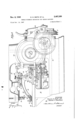
- E. B.- Fig. 1 is a right side elevational View of an eye- Allen. dated y 1920, there is let machine embodying the invention, portions incorporated in the machine the usual eyeletu of the machine being broken away.
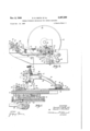
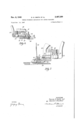
- ter shaft It which makes one revolution prior to Fig. 2 is an enlarged top plan view of portions Sewing and en comes to rest, and a Second of the work-clamp and of the machine-frame, auxiliary shaft 20 which is stationary dur the showing the actuating mechanism for imparting Operation of e Shaft 59 and main-Shaft 95 and the required thread-trimming and -nipping makes one revolution after the sewing is commotions to the trimmer.
- Fig. 3 is a plan View of the feed-wheel, together Stitching, Such as t p ning of the work-clamp.
- Fig. 6 is an enlarged vertical sectional view rapidly turnin the feed-wheel at one sweep fromv taken substantially along the line B-6, Fig. 2. its position at the end of a sewing operation to initial position ready to begin a new cycle of operations.
- the work is adapted to be held in a workclamp during the sewing operation.
- the workclamp which is shown in the drawings forms the subject of pending application Serial No. 786,014, filed Nov. 14, 194'? in the name of H. C. Faulkner, and includes lower clamp-plates 23, 36 and opposed upper clamp-feet 3
- the clamp-feet are pivotally fastened by means of pivot-screws 33, 34 to the free ends of the arched clamp-arms 35 and 36, each of which is fulcrumed at its rear end on a hinge-pin 31 provided .in;a supporting bracket 38, only the bracket for the clamp-arm 35 being shown in the drawings.
- is yieldingly held against the work, when the work-clamp is closed, by a coil-spring 39 which is interposed between the arm 35 and a thumbnut 40 threaded on a pull-rod 4
- a coil-spring 39 which is interposed between the arm 35 and a thumbnut 40 threaded on a pull-rod 4
- suitable toggle mechanism connected .Withthe pull-rod 4
- the clamp-arms 35, 36 are appreciably arched and the fulcrum supports for said arms are disposed considerably back from the feet 3
- the needle-thread trimming and -nipping mechanism now to be described-comprises a trimmer-blade 42 and .an overlying nipper-blade 43 (Figs. 4, and '7), the shanks of which are secured to the lower end of the usual vertical rockshaft 44 journaled in the clamp-foot 3
- This construction is substantially the sameas that disclosed in the U. :S. patent of E. B. Allen, No. 885,310, dated April '21, 1908.
- the thread-trimming and nipping blades 42 and 43 are adapted tooperate ina horizontal slot defined between a section 45 of the clamp-foot 3
- the nipperblade 43 cooperates with the section 45 as shown in Fig. 7 to hold the beginning end of the thread during the sewing of the first portion of the eyelet.
- the trimmer-blade 42 has a sharpened edge which cooperates with an edge on the detachable section 46 in severing the needle-thread.
- The'trimmer-blade carrying rock-shaft 44 has fixed .on its upper end a rock-arm 41 connected by a link 48 to a rock-lever 49 freely pivoted on a'stud 50 threaded into the clamp-foot 3
- a rock-lever 49 freely pivoted on a'stud 50 threaded into the clamp-foot 3
- embraced by .the socketed front end of an actuating link 52 arched in substantial conformity with the clamp-arm 35 (Fig. 1) and connected at its rear end to the upper end of a trimmer-opening lever 53 pivoted intermediate its ends on a stud 54 threaded into the supporting bracket 33.
- a projection 55 Rising from the upper end of the trimmeropening lever 53 is a projection 55 to which is attached one end of a coil-spring 56 connected at its other end to an ear 51 secured to the clamparm 35, the coil-spring acting to bias the trimmeropening lever 53 into trimmer-blade closed position determined by a buffer pad 58 secured to the trimmer-opening lever 53 contacting an upstanding stop 59 provided on the clamp-arm 35.
- a buffer pad 58 secured to the trimmer-opening lever 53 contacting an upstanding stop 59 provided on the clamp-arm 35.
- the thread-trimming and -nipping blades are adapted to be operated twice for each complete stitching cycle, once before the sewing is completed to retrimt-he beginning end of the needlethread, the operation being performed preferably after the sewing has progressed to the point where the beginning endcannot be sewed in or bound down by the stitching, and a second time after the sewing is completed to cut the needle-thread close to the work and hold the beginning end of the needle-thread for the beginning of the next sewing operation.
- a thread-trimming mechanism having substantially the same sequence of operations is disclosed, for example, in the U. S. patent of A. R. Wood, No. 1,839,823,.issued Jan. 5, 1,932.
- the first or retrim operation isperformed by meansactuated by the feed-cam 2
- This means preferably comprises a vertically disposed rock-shaft 66 journaled in the bed 56 and having attached to its lower end an arm 6
- a rock-lever 63 Secured to the upper end of the rock-shaft 66 is a rock-lever 63 provided at its outer end with a slot 64 disposed to receive a screw 65 threaded into a push-lever 66 fulcrumed at one end on a pivot-stud 61.
- the free end of the push-lever 66 is arranged to swing into engagement with the lower end of the trimmeropening lever 53.
- a spring 68 bears against the push-lever 56 and urges itinto an inoperative position determined by a stop-pin 66.
- This movement of the push-lever 66 turns the trimmer-opening lever 53 from the full line position in Fig. 5 to the dotted line position.
- This turning of the trimmer-opening lever 53 gradually moves the trimmerand nipper-blades 42 and 43 into an open position, shown in Fig. 4.
- the beginning end of the needlethread is released .and the trimmer-blade is set for its retrim stroke. As the feed-cam 2
- the retrim-cam 62 advances to a point where its drop-off passes the end of the arm SI and when this occurs the coil-spring 56 snaps the link 52 ina direction to close the trimmar-blade 42 upon and retrim the beginning end of the needle-thread close to the work.
- the spring 68 acts simultaneously with the coil-spring 56 in returning the push-lever 66 and its associated connections to their inoperative position.
- a second means actuated by the single rotation of the auxiliary shaft for operating the rock-shaft 60 preferably comprises a rock-arm Ill (Figs. 1 and 5) secured to the rock-shaft 60 and extending substantially horizontally immediately above the level of the feed-cam 2
- the pawl 26 is provided with an upstanding pin I3 which is disposed so that, as the pawl 26 is actuated by the pitman 24 to effect the rapid turning of the feed-cam 2
- a needle-thread trimmer and nipping device constructed so that the nipperblade is not accidentally shifted and the beginning thread-end released by the tilting of the work-clamping foot on its pivotal support during the insertion or removal of Work or during the traversing of any unevenness in the material due to cross-seams or the like.
- the actuating mechanism for the trimmer and nipping device is arranged so that ample clearance space is provided beneath the work-clamping feet to permit convenient manipulation of the work and to permit the placing of the stitched pattern back from the edge of the work.
- the actuating connections are designed so that they will not interfere with the movement of the work-clamp into and out of work-cutting position, and the position of the pivot 54 of the trimmer-opening lever 53 relative to the hinge pin 31 of the clamparm 35 is such that during the opening and closing of the work-clamp the bufier pad 58 slides up and down on the face of the stop-lug 59 in a direction substantially normal to the axis of the link '52.
- no endwise movement is imparted to the link 52 during the opening and closing of the work-clamp and consequently the trimmerand nipper-blade is not disturbed.
- a group-stitch sewing machine having a work-clamp provided with an upper clamp-foot pivotally mounted for tilting movement about a fulcrum-axis, a thread-trimmer and -nipper device carried by said upper clamp-foot, and actuating' mechanism for operating said thread-trimmer and -nipper device; said mechanism including a pair of elements carried by said work-clamp and a ball-and-socket connection between'said elements with the-center of the balldisposedin alinement with the fulcrum-axis of said clampfoot when said thread-trimmer and -nipper device is closed.
- a group-stitch sewing machine having a work-clamp provided with an upper clamp-arm, a bracket to which said clamp-arm is pivoted, a clamp-foot mounted on one end of said clamparm for tilting movement about a fulcrum-axis, a thread-trimmer and -nipper device carried by said clamp-foot, and actuating mechanism for operating said thread-trimmer and -nipper device, said actuating mechanism including a rocklever pivoted on said clamp-foot, a trimmeropening lever fulcrumed on said bracket, a link connected at one end to said rock-lever and at its other end to said trimmer-opening lever, the point of connection between said link and rocklever being in alinement with the fulcrum-axis of the clamp-foot when said thread-trimmer and -nipper device is closed, and means for operating said trimmer-opening lever.
- a group-stitch sewing machine having a work-clamp, provided with an arched upper clamp-arm, a bracket to which one end of said clamp-arm is pivoted, a clamp-foot mounted on the other end of said clamp-arm; a threadtrimmer and -nipper device carried by said clamp-foot, and actuating mechanism for operating said thread-trimmer and -nipper device, said actuating mechanism including a rock-lever pivoted on said clamp-foot and operatively associated with said thread-trimmer and -nipper device, a trimmer-opening lever pivoted on said bracket adjacent the pivotal support of said clamp-arm, a link shaped to conform substantially with the arched clamp-arm and connecting said trimmer-opening lever to said rock-lever, and automatically controlled means for operating said trimmer-opening lever.
- a group-stitch sewing machine having stitch-forming mechanism, a feed-cam for effecting the distribution of stitches in a given pattern, feed-cam rapid-turning means for returning the feed-cam to its initial position after the stitching is completed, a thread-trimmer and -nipper device, and means for actuating said device twice for each complete stitching cycle, said means including a rock-shaft, means operatively connecting said rock-shaft to said thread-trimmer and -nipper device, a reset cam on said feed-cam, a rock-arm secured on said rock-shaft and disposed for engagement by said reset cam to effect one of the operations of said thread-trimmer and .-nipper device, and a second rock-arm secured to said rock-shaft and arranged for engagement by said feed-cam rapid-turning means for efiectin the other operation of said thread-trimmer and -nipper device.
- a group-stitch sewing machine having a work-clamp provided with an upper clamp-arm, a clamp-foot mounted on said clamp-arm for tilting movement about a fulcrum-axis, a threadtrimmer and -nipper device carried by said clamp-foot, and actuating mechanism for operating said thread-trimmer and -nipper device, said actuating mechanism including a trimmer-carrying rock-shaft, a rock-arm secured to said rock-shaft, a rock-lever pivoted on said clampfoot, a link connecting said rock-arm to said IQOKFIQYBI', a second link connected to said rock- REFERENCES CI'IIEI) 16V nowadays afipomt m ahusement wi fulcruim'
- the following references are of record in the axis of; said clampriootwhen, said thread-trimfile this patent,
Landscapes
- Engineering & Computer Science (AREA)
- Textile Engineering (AREA)
- Physics & Mathematics (AREA)
- Electromagnetism (AREA)
- General Physics & Mathematics (AREA)
- Sewing Machines And Sewing (AREA)
Priority Applications (4)
| Application Number | Priority Date | Filing Date | Title |
|---|---|---|---|
| US786016A US2487389A (en) | 1947-11-14 | 1947-11-14 | Thread-trimming mechanism for sewing machines |
| AT169689D AT169689B (de) | 1947-11-14 | 1948-11-03 | Maschine zum Nähen einer Stichgruppe |
| DEP30246A DE838849C (de) | 1947-11-14 | 1949-01-01 | Naehmaschine |
| DEP30247A DE830286C (de) | 1947-11-14 | 1949-01-01 | Maschine zum Naehen von Stichgruppen |
Applications Claiming Priority (1)
| Application Number | Priority Date | Filing Date | Title |
|---|---|---|---|
| US786016A US2487389A (en) | 1947-11-14 | 1947-11-14 | Thread-trimming mechanism for sewing machines |
Publications (1)
| Publication Number | Publication Date |
|---|---|
| US2487389A true US2487389A (en) | 1949-11-08 |
Family
ID=25137347
Family Applications (1)
| Application Number | Title | Priority Date | Filing Date |
|---|---|---|---|
| US786016A Expired - Lifetime US2487389A (en) | 1947-11-14 | 1947-11-14 | Thread-trimming mechanism for sewing machines |
Country Status (3)
| Country | Link |
|---|---|
| US (1) | US2487389A (de) |
| AT (1) | AT169689B (de) |
| DE (2) | DE838849C (de) |
Cited By (3)
| Publication number | Priority date | Publication date | Assignee | Title |
|---|---|---|---|---|
| US3420199A (en) * | 1965-05-28 | 1969-01-07 | Reece Corp | Combination presser foot and thread cut-off |
| US4727817A (en) * | 1984-09-14 | 1988-03-01 | Suzuki Manufacturing, Ltd. | Buttonhole sewing machine |
| US4903619A (en) * | 1984-09-14 | 1990-02-27 | Suzuki Manufacturing, Ltd. | Buttonhole sewing machine |
Families Citing this family (1)
| Publication number | Priority date | Publication date | Assignee | Title |
|---|---|---|---|---|
| DE102012205049A1 (de) * | 2012-03-29 | 2013-10-02 | Dürkopp Adler AG | Faden-Schneid-Baugruppe für eine Schnürloch-Nähmaschine |
Citations (1)
| Publication number | Priority date | Publication date | Assignee | Title |
|---|---|---|---|---|
| US1066862A (en) * | 1911-10-05 | 1913-07-08 | Singer Mfg Co | Thread-cutting device. |
-
1947
- 1947-11-14 US US786016A patent/US2487389A/en not_active Expired - Lifetime
-
1948
- 1948-11-03 AT AT169689D patent/AT169689B/de active
-
1949
- 1949-01-01 DE DEP30246A patent/DE838849C/de not_active Expired
- 1949-01-01 DE DEP30247A patent/DE830286C/de not_active Expired
Patent Citations (1)
| Publication number | Priority date | Publication date | Assignee | Title |
|---|---|---|---|---|
| US1066862A (en) * | 1911-10-05 | 1913-07-08 | Singer Mfg Co | Thread-cutting device. |
Cited By (4)
| Publication number | Priority date | Publication date | Assignee | Title |
|---|---|---|---|---|
| US3420199A (en) * | 1965-05-28 | 1969-01-07 | Reece Corp | Combination presser foot and thread cut-off |
| US4727817A (en) * | 1984-09-14 | 1988-03-01 | Suzuki Manufacturing, Ltd. | Buttonhole sewing machine |
| US4903619A (en) * | 1984-09-14 | 1990-02-27 | Suzuki Manufacturing, Ltd. | Buttonhole sewing machine |
| US5067422A (en) * | 1984-09-14 | 1991-11-26 | Suzuki Manufacturing Co., Ltd. | Buttonhole sewing machine |
Also Published As
| Publication number | Publication date |
|---|---|
| DE830286C (de) | 1952-02-04 |
| DE838849C (de) | 1952-05-12 |
| AT169689B (de) | 1951-12-10 |
Similar Documents
| Publication | Publication Date | Title |
|---|---|---|
| US2889790A (en) | Apparatus for producing piped garment openings | |
| GB811605A (en) | Improvements in or relating to sewing machines suitable for use in sewing together an upper and sole member of a shoe | |
| US1839854A (en) | Automatic operator for sewing machines | |
| US1841102A (en) | Thread-cutting mechanism for sewing machines | |
| US1955994A (en) | Feed-wheel stop for buttonhole sewing machines | |
| US2301797A (en) | Buttonhole sewing machine | |
| US2335827A (en) | Article attaching machine | |
| US1920944A (en) | Thread-cutting mechanisms for sewing machines | |
| US2499335A (en) | Thread-trimming and pull-off mechanism for sewing machines | |
| US1051998A (en) | Thread-cutting device. | |
| US1255970A (en) | Sewing-machine. | |
| US856014A (en) | Buttonhole-sewing machine. | |
| US1404727A (en) | Thread cutting and nipping mechanism for sewing machines | |
| US439679A (en) | Cutting mechanism for button-hole sewing-machines | |
| US2550611A (en) | Thread trimming mechanism for sewing machines | |
| US1394075A (en) | Sewing-machine | |
| US271666A (en) | Chusetts | |
| US2028005A (en) | Sewing machine | |
| US2752871A (en) | Thread trimming mechanisms for sewing machines | |
| US2440227A (en) | Sewing machine safety device | |
| US3463105A (en) | Thread cutting mechanism in a sewing machine | |
| US2426543A (en) | Thread-cutting mechanism for sewing machines | |
| US798130A (en) | Thread cutting and holding device for sewing-machines. | |
| US1272066A (en) | Sewing-machine having thread-cutting device. | |
| US1559539A (en) | Buttonhole-sewing machine |