US2488024A - Delayed-action switch - Google Patents
Delayed-action switch Download PDFInfo
- Publication number
- US2488024A US2488024A US637219A US63721945A US2488024A US 2488024 A US2488024 A US 2488024A US 637219 A US637219 A US 637219A US 63721945 A US63721945 A US 63721945A US 2488024 A US2488024 A US 2488024A
- Authority
- US
- United States
- Prior art keywords
- handle
- switch
- stem
- head
- suction cup
- Prior art date
- Legal status (The legal status is an assumption and is not a legal conclusion. Google has not performed a legal analysis and makes no representation as to the accuracy of the status listed.)
- Expired - Lifetime
Links
- 230000000994 depressogenic effect Effects 0.000 description 3
- 238000010276 construction Methods 0.000 description 2
- 210000005069 ears Anatomy 0.000 description 2
- 230000000694 effects Effects 0.000 description 2
- 238000009413 insulation Methods 0.000 description 2
- 238000000926 separation method Methods 0.000 description 2
- 230000001276 controlling effect Effects 0.000 description 1
- 239000011810 insulating material Substances 0.000 description 1
- 239000000463 material Substances 0.000 description 1
- 239000003973 paint Substances 0.000 description 1
- 230000001105 regulatory effect Effects 0.000 description 1
- 239000007787 solid Substances 0.000 description 1
- 229920003002 synthetic resin Polymers 0.000 description 1
- 239000000057 synthetic resin Substances 0.000 description 1
Images
Classifications
-
- H—ELECTRICITY
- H01—ELECTRIC ELEMENTS
- H01H—ELECTRIC SWITCHES; RELAYS; SELECTORS; EMERGENCY PROTECTIVE DEVICES
- H01H23/00—Tumbler or rocker switches, i.e. switches characterised by being operated by rocking an operating member in the form of a rocker button
- H01H23/02—Details
- H01H23/12—Movable parts; Contacts mounted thereon
-
- G—PHYSICS
- G04—HOROLOGY
- G04F—TIME-INTERVAL MEASURING
- G04F1/00—Apparatus which can be set and started to measure-off predetermined or adjustably-fixed time intervals without driving mechanisms, e.g. egg timers
-
- Y—GENERAL TAGGING OF NEW TECHNOLOGICAL DEVELOPMENTS; GENERAL TAGGING OF CROSS-SECTIONAL TECHNOLOGIES SPANNING OVER SEVERAL SECTIONS OF THE IPC; TECHNICAL SUBJECTS COVERED BY FORMER USPC CROSS-REFERENCE ART COLLECTIONS [XRACs] AND DIGESTS
- Y10—TECHNICAL SUBJECTS COVERED BY FORMER USPC
- Y10T—TECHNICAL SUBJECTS COVERED BY FORMER US CLASSIFICATION
- Y10T74/00—Machine element or mechanism
- Y10T74/18—Mechanical movements
- Y10T74/18888—Reciprocating to or from oscillating
- Y10T74/18896—Snap action
Definitions
- a suction cup delay mechanism comprising a suction cup, a smooth plate positioned to be engaged thereby, and a stem for pressing the cup and plate together, a head on the stem, means on the handle adapted when the handle is rocked in one direction to engage one side of the head and press the cup and plate together, a, spring arm on the handle engaging the other side of the head and tending to press the cup and plate apart with an increased tension when the handle is rocked in the other direction, and a circuit controlling element actuated by said head.
- a suction cup delay mechanism comprising a suction cup, a smooth plate positioned to be engaged thereby, and a stem for pressing the cup and plate together, a head on the stem, means on the handle adapted when the handle is rocked in one direction to en age one side of the head and press the cup and plate together, a spring arm on the handle engaging the other side of the head and tending to press the cup and plate apart with an increased tension when the handle is rocked in the other direction, a stationary contact, a spring arm, a movable contact thereon, and means actuated by said head for moving the movable contact against the force of the spring arm.
Landscapes
- Physics & Mathematics (AREA)
- General Physics & Mathematics (AREA)
- Tumbler Switches (AREA)
Description
Nov. 15, 1949 T. J. 'MUDON 2,488,024
DELAYED-ACTION SWITCH Filed Dec. 26, 1945 2 Sheets-Sheet 1 fiu/enZf" 721077235 Mud 0n Nov. 15, 1949 T, J. MUDON 2,488,024
DELAYED- ACTION SWITCH Filed Dec. 26, 1945 2 Sheets-Sheet 2 q E 26 f'u/eni or'" 10 77W; sJffua on UNITED STATES PATENT OFFICE DELAYED-ACTION swrrcn Thomas J. Mudon, Chicago, 111., assignor to T. J. Mudolr; Co. Inc., Chicago, 11]., a corporation of Illino Application December 26, 1945, Serial No. 637,219
9 Claims. (Cl. 200--34) My invention relates to switches and is particularly directed toward a novel switch construction of the general type shown and claimed in my prior application, Serial No. 558,207, filed October 11, 1944. It is the principal purpose of my invention to provide a simplified switch construction of this character embodying a suction cup time delay mechanism which is enclosed for protection, wherein the switch handle itself carries means for engaging the stem 01' the time delay mechanism to cause both time delay action, and at the will of the operator, instantaneous operation of the switch.
It is a further purpose of my invention to provide in a switch of this character, a novel combination between the time delay apparatus and the contact making and breaking mechanism, whereby simple spring contact arms may be employed. A further purpose of my invention is to provide a switch mechanism embodying means for delaying the opening of the switch in combination with a casing having provision for right hand or left hand wiring, or both, and single pole or double pole contacts.
My invention is embodied in a device using a simple toggle switch handle wherein the switch handle in combination with a suction cup having a stem fixed thereto provides means for getting either instantaneous opening and closing of a circuit in response to movement of the handle, or instantaneous closing of the switch contacts with a delay in the opening of the switch contacts after the handle is moved to the open position for a preset time. The handle itself carries the means whereby the time delay may be regulated. In addition the stem of the suction cup delay device serves to operate the contacts in order to cause opening of the circuit. Thus the number of switch parts is reduced to a very few, and the switch may be made small in size with all of the advantages of a simple toggle switch plus the time delay features.
The nature and advantages of my invention will appear more fully as the description proceeds in connection with the accompanying drawings, wherein a preferred form of the invention is shown. It should be understood, however, that the drawings and description are illustrative only, and are not to be taken as limiting the invention except insofar as it is limited by the claims.
In the drawings:
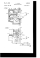
Figure 1 is a longitudinal sectional view through a switch embodying my invention;
Figure 2 is a view partly in side elevation and partly in section, showing the switch handle 2 moved to position to cause an opening of the contacts after the time delay;
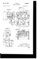
Figure 3 is a fragmentary sectional view taken on the line 3 3 of Figure 4;
Figure 4 is a plan view with the handle removed of the switch mechanism;
Figure 5 is a sectional view taken on the line 55 of Figure 4;
Figure 6 is a side view of the switch taken from the opposite side to that of Figure 2 and showing wiring terminals as applied to both sides of the switch; and
Figure 7 is a fragmentary sectional view illustrating a modified form of the contact operating mechanism whereby the contact spring is directly actuated by the stem of the suction cup.
Referring now in detail to the drawings, my invention is shown as embodied in a casing III which may be made of any suitable material such as a molded synthetic resin. This casing has a well at H, in which a container 12 houses a suction cup I: of the type shown in my prior application, Serial Number 592,093. The well of the switch casing also has a slight extension ll at one side of the circular portion H in which a spring bar I5 is secured by a screw bolt IS. The casing has screw threaded portions at I! and It by which a mounting plate I! can be attached thereto. The mounting plate is provided with ears 20 to secure a switch handle 2|. The handle is pivoted on a pin 22' that extends through the ears 20. Preferably the handle is made of a solid body of insulating material, and has embedded in the end thereof, a luminous element 23. This element 22 is made visible in the darkness by the use of the so-called luminous paint which has the characteristic of giving oil light after having been exposed to the light for a substantial length of time.
The suction cup device I3 has a stem 24 that projects through a sleeve 24' toward the switch handle 2i. The stem 24 has a fiat head 25 thereon, and the handle 2| carries an adjustable screw threaded pin 26 for engaging the head 25, and pushing the stem downward to set the suction cup. The pin 26 has a slot 26' in the outer end thereof, so that it can be turned by a set screw to vary the amount it extends below the handle and thus vary the degree to which the suction cup is pressed downward.
The switch handle has a forked bar 21 fixed thereon opposite the pin 28 by means of a screw 28. The forked bar 21 has an end portion 29 that is adapted to engage the mounting plate I! to limit the movement oi the handle 2| toward 3 contact closing position. There are two forks 3| offset downwardly from the main body portion of the bar 21, these two forks being positioned so that as the handle is swung from the position shown in Figure 1 to the position shown in Figure 2, these forks move under the head 25 so as to tend to lift it. In addition to the forks 33 the handle carries a pair of spring arms 3 [-32 directly engaging the head 25 in all positions of the switch. These spring arms are alined with the forks 36 so that the forks 3|! may pick up the spring arms and positively lift the head 25 at any time that is desired. The' spring arms 3l-32 are sufficiently light that when the suction cup I3 is forced down against a polished surface l3A, provided in the bottom of the container 12, they will merely furnish the necessary lift to gradually cause the suction'cup i3 to creep and release itself from the surface I3A. Of course the forks 30, when they are moved into position, may exert enough force to lift the suction cup instantaneously.
The contacts. and wiring terminals for the switch are mounted in slots 33, 34, 35 and 35 provided in opposite sides of the casing Ill. The slots 33 and 35 are substantially deeper than the slots 34 and 36. Each slot has grooves 31 and 38 to receive wiring terminal plates 39 and 46, or insulating plates 4! and 42, which are used to fill the slots. As shown, the wiring terminal and contact carrying member 39 has a screw 43 for screwing a wire thereto, and in addition carries a contact point 44. The wiring terminal '40 has a screw 45 for screwing the lead thereto,
and which serves as a mounting for a spring 46, the free end of which has a contact 41 thereon positioned to engage the contact 44. A block 48 of insulation is also mounted on the free end of the spring 46, and projects beyond the spring so as to engage an actuating finger 49. The actuating finger is mounted on a rocker bar 50 which has spaced arms and 52 positioned to engage the head 25 as it is moved upward by the springs 3| and 32. The rocker bar 50 is pivoted in a yoke 53 which is mounted directly on the top of the container I2. The yoke 53 is also riveted by rivets 54 and 55 to the mounting plate l9 so as positively to position the container l2 and the handle 2| with respect to each other. Thus all of the parts of the switch are carried by the mounting plate [9 with the exception of the spring bar l5. The spring bar I5 is adapted to engage the rear end portion 29 of the bar 21 and form at the bend I5A thereof a stop which determines the position of the handle for time delay actuation of the switch. When immediate operation of the switch is desired the operator merely has to apply additional pressure to the switch handle in a downward direction when the handle is in the position shown in Figure 2 and this will operate to move the forks 30 toward the head 25 in position to back up the springs 3i and 32 so closely that the head will be forced against the power of the suction cup into position to open the contacts 44 and 41.
In the form of device shown in Figure 7 the rocker bar 50 is dispensed with and the head 25' is modified so as to provide a contact lifting finger 56 that will engage the bar 48 of insulation on the spring 46. The head is so shaped that the yoke 53 serves as a guide therefor, to prevent any rotation thereof that might otherwise get the actuating finger 56 out of position.
that the nature and advantages of my invention will be clear to those skilled in this art.
Having thus described my invention, I claim:
1. A time delay switch comprising a suction cup, a smooth plate positioned to be engaged thereby, a stem for pressing the cup and plate together, a head on the stem, a pair of contacts, a spring arm carrying one contact and normally holding it against the other contact in opposition to said head, a pivoted lever having a handle, means on said leveroperable to engage said head and move the suction cup and plate together when the lever is rocked in one direction. sprin means on said lever engaging the head and urging the suction cup and plate apart when the lever is rocked in the other direction to separate said contacts.
2. In a switch, a mounting plate, a handle pivoted thereon. a suction cup delay mechanism comprising a suction cup, a smooth plate positioned to be engaged thereby, and a stem for pressing the cup and plate together, a head on the stem, means on the handle adapted when the handle is rocked in one direction to engage one side of the head and press the cup and plate together, a, spring arm on the handle engaging the other side of the head and tending to press the cup and plate apart with an increased tension when the handle is rocked in the other direction, and a circuit controlling element actuated by said head.
3. In a switch, a mounting'plate, a handle pivoted thereon, a suction cup delay mechanism comprising a suction cup, a smooth plate positioned to be engaged thereby, and a stem for pressing the cup and plate together, a head on the stem, means on the handle adapted when the handle is rocked in one direction to en age one side of the head and press the cup and plate together, a spring arm on the handle engaging the other side of the head and tending to press the cup and plate apart with an increased tension when the handle is rocked in the other direction, a stationary contact, a spring arm, a movable contact thereon, and means actuated by said head for moving the movable contact against the force of the spring arm.
4. A time delay switch comprising a mounting plate, a handle pivoted thereon for rockin movement, a suction cup casing spaced from the plate, means securing the casing to the plate, a suction cup in the casing, a stem on the cup projecting toward the mounting plate and slidable through the casing whereby the suction cup may be pushed toward and away from the interior wall surface of the casing facing the mounting plate, an adjustable pin on the handle positioned to engage the stem and push it away from the plate when the handle is rocked in one direction, a spring yoke on the handle engaged with the stem to urge it toward the mounting plate when the handle is rocked in the other direction, and circuit control means actuated by said stem.
5. A time delay switch comprising a pair of contacts, means to move one of said contacts away from the other, a suction cup delay mechanism having a stem operatively connected to said means,-a rocking switch handle having a spring means thereon yieldingly urging the stem in one direction against the delay of said suction cup when the handle is rocked in one direction, and means on the handle operable upon From the foregoing description it is believed further movement of the handle in said direction for positively moving the stem to effect separation of said contacts.
6. A time delay switch comprising a pair of contacts, means to move one of said contacts away from the other, a suction cup delay mechanism having a stem operatively connected to said means, a rocking switch handle having a spring means thereon yieldingiy urging the stem in one direction against the delay of said suction cup when the handle is rocked in one direction, means on the handle operable upon further movement of the handle in said direction for positively moving the stem to effect separation of said contacts, and means engaging the handle, yieldingiy to oppose said further movement thereof.
7. In a switch of the character described, a pair of contacts and means to move one of said contacts away from the other comprising a rocking lever, a suction cup delay mechanism having a stem having a head-positioned to be engaged and depressed by a portion 01' said lever, a spring on said lever extending on the opposite side of said head from said portion to yieldingiy lift the stem, and a contact moving member positioned in the path of said head.
8. In a switch of the character described, a pair of contacts and means to move one of said contacts away from the other comprising a rocking lever, a suction cup delay mechanism having a stem having a head positioned to be engaged and depressed by a portion of said lever, a spring on said lever extending on the opposite side of said head from said portion to yieldingiy lift the stem, and a contact moving member positioned in the path of said head, said portion of the lever including a stem head engaging part adjustable in the lever to project more or less toward the stem to vary the depression thereof.
9. In a switch of the character described, a pair of contacts and means to move one 01' said contacts away from the other comprising a rocking lever, a suction cup delay mechanism having a stem having a head positioned to be engaged and depressed by a portion of said lever, a spring on said lever extending on the opposite side of said head from said portion to yieldingiy lift the stem, a spring stop adjacent said lever ofiering increased resistance to movement of said lever when it reaches a position to cause said spring to yieldingly lift the stem.
THOMAS J. MUDON.
REFERENCES CITED FOREIGN PATENTS Country Date Germany Apr. 22, 1940 Number
Priority Applications (1)
| Application Number | Priority Date | Filing Date | Title |
|---|---|---|---|
| US637219A US2488024A (en) | 1945-12-26 | 1945-12-26 | Delayed-action switch |
Applications Claiming Priority (1)
| Application Number | Priority Date | Filing Date | Title |
|---|---|---|---|
| US637219A US2488024A (en) | 1945-12-26 | 1945-12-26 | Delayed-action switch |
Publications (1)
| Publication Number | Publication Date |
|---|---|
| US2488024A true US2488024A (en) | 1949-11-15 |
Family
ID=24555037
Family Applications (1)
| Application Number | Title | Priority Date | Filing Date |
|---|---|---|---|
| US637219A Expired - Lifetime US2488024A (en) | 1945-12-26 | 1945-12-26 | Delayed-action switch |
Country Status (1)
| Country | Link |
|---|---|
| US (1) | US2488024A (en) |
Cited By (4)
| Publication number | Priority date | Publication date | Assignee | Title |
|---|---|---|---|---|
| US2666340A (en) * | 1950-03-29 | 1954-01-19 | Hunt Wilde Corp | Handgrip |
| US2921162A (en) * | 1957-09-30 | 1960-01-12 | Charles L Craddock | Circuit interrupter |
| US3103660A (en) * | 1959-07-14 | 1963-09-10 | George B Ticktin | Body supported time interval indicator with collapsible timing means |
| US6252185B1 (en) | 1997-10-28 | 2001-06-26 | Matsushita Electric Works, Ltd. | Delay switch with delay unit |
Citations (1)
| Publication number | Priority date | Publication date | Assignee | Title |
|---|---|---|---|---|
| DE690298C (en) * | 1938-06-02 | 1940-04-22 | Heinrich Kratz | Time switch |
-
1945
- 1945-12-26 US US637219A patent/US2488024A/en not_active Expired - Lifetime
Patent Citations (1)
| Publication number | Priority date | Publication date | Assignee | Title |
|---|---|---|---|---|
| DE690298C (en) * | 1938-06-02 | 1940-04-22 | Heinrich Kratz | Time switch |
Cited By (4)
| Publication number | Priority date | Publication date | Assignee | Title |
|---|---|---|---|---|
| US2666340A (en) * | 1950-03-29 | 1954-01-19 | Hunt Wilde Corp | Handgrip |
| US2921162A (en) * | 1957-09-30 | 1960-01-12 | Charles L Craddock | Circuit interrupter |
| US3103660A (en) * | 1959-07-14 | 1963-09-10 | George B Ticktin | Body supported time interval indicator with collapsible timing means |
| US6252185B1 (en) | 1997-10-28 | 2001-06-26 | Matsushita Electric Works, Ltd. | Delay switch with delay unit |
Similar Documents
| Publication | Publication Date | Title |
|---|---|---|
| US2511271A (en) | Electric switch actuator | |
| US2473848A (en) | Circuit breaker | |
| US2528756A (en) | Toggle-lever switch | |
| US2458518A (en) | Snap acting device | |
| US2457153A (en) | Sealed switch | |
| US2921159A (en) | Push button control device | |
| GB1326186A (en) | Circuit breaker with on off and trip indication | |
| GB655389A (en) | Improvements in or relating to electric switches of the push-push type | |
| GB1399401A (en) | Electric switches | |
| US2337001A (en) | Snap switch | |
| US2040181A (en) | Pressure switch | |
| US2111311A (en) | Electric switch | |
| GB1098324A (en) | Electrical switches | |
| US2515528A (en) | Snap switch structure | |
| US2304400A (en) | Snap switch | |
| US2558908A (en) | Circuit breaker switch | |
| US2469976A (en) | Mechanism for sequential contact switches | |
| US2428172A (en) | Mechanism for precision switches | |
| US2616996A (en) | Snap switch | |
| US3931484A (en) | Lever operated limit switch having a mechanism to increase overtravel | |
| US2210084A (en) | Thermally actuated switch | |
| US2987592A (en) | Silent switches | |
| US2466292A (en) | Electric switch control mechanism | |
| US1877923A (en) | Electric switch | |
| US2384772A (en) | Sewing machine motor controller |