US2489244A - Combustion chamber burner - Google Patents
Combustion chamber burner Download PDFInfo
- Publication number
- US2489244A US2489244A US546846A US54684644A US2489244A US 2489244 A US2489244 A US 2489244A US 546846 A US546846 A US 546846A US 54684644 A US54684644 A US 54684644A US 2489244 A US2489244 A US 2489244A
- Authority
- US
- United States
- Prior art keywords
- chamber
- combustion
- burner
- orifice
- products
- Prior art date
- Legal status (The legal status is an assumption and is not a legal conclusion. Google has not performed a legal analysis and makes no representation as to the accuracy of the status listed.)
- Expired - Lifetime
Links
- 238000002485 combustion reaction Methods 0.000 title description 66
- 239000000047 product Substances 0.000 description 40
- 239000007789 gas Substances 0.000 description 38
- 239000011521 glass Substances 0.000 description 20
- 239000000446 fuel Substances 0.000 description 17
- 239000000203 mixture Substances 0.000 description 17
- 238000005192 partition Methods 0.000 description 9
- 239000003365 glass fiber Substances 0.000 description 8
- 229910052751 metal Inorganic materials 0.000 description 7
- 239000002184 metal Substances 0.000 description 7
- 238000000034 method Methods 0.000 description 6
- 239000002737 fuel gas Substances 0.000 description 5
- 239000011819 refractory material Substances 0.000 description 5
- ATUOYWHBWRKTHZ-UHFFFAOYSA-N Propane Chemical compound CCC ATUOYWHBWRKTHZ-UHFFFAOYSA-N 0.000 description 4
- 230000002238 attenuated effect Effects 0.000 description 4
- 239000000835 fiber Substances 0.000 description 3
- 239000000463 material Substances 0.000 description 3
- 230000008018 melting Effects 0.000 description 3
- 238000002156 mixing Methods 0.000 description 3
- 206010037660 Pyrexia Diseases 0.000 description 2
- 229910001080 W alloy Inorganic materials 0.000 description 2
- 239000000919 ceramic Substances 0.000 description 2
- 229910010293 ceramic material Inorganic materials 0.000 description 2
- 230000000295 complement effect Effects 0.000 description 2
- 238000007599 discharging Methods 0.000 description 2
- 238000004519 manufacturing process Methods 0.000 description 2
- 238000002844 melting Methods 0.000 description 2
- 150000002739 metals Chemical class 0.000 description 2
- VNWKTOKETHGBQD-UHFFFAOYSA-N methane Chemical compound C VNWKTOKETHGBQD-UHFFFAOYSA-N 0.000 description 2
- 239000001294 propane Substances 0.000 description 2
- FRWYFWZENXDZMU-UHFFFAOYSA-N 2-iodoquinoline Chemical compound C1=CC=CC2=NC(I)=CC=C21 FRWYFWZENXDZMU-UHFFFAOYSA-N 0.000 description 1
- FDQGNLOWMMVRQL-UHFFFAOYSA-N Allobarbital Chemical compound C=CCC1(CC=C)C(=O)NC(=O)NC1=O FDQGNLOWMMVRQL-UHFFFAOYSA-N 0.000 description 1
- 229910052580 B4C Inorganic materials 0.000 description 1
- 241000288673 Chiroptera Species 0.000 description 1
- VYZAMTAEIAYCRO-UHFFFAOYSA-N Chromium Chemical compound [Cr] VYZAMTAEIAYCRO-UHFFFAOYSA-N 0.000 description 1
- 101150110302 RND3 gene Proteins 0.000 description 1
- QCWXUUIWCKQGHC-UHFFFAOYSA-N Zirconium Chemical compound [Zr] QCWXUUIWCKQGHC-UHFFFAOYSA-N 0.000 description 1
- LNSPFAOULBTYBI-UHFFFAOYSA-N [O].C#C Chemical group [O].C#C LNSPFAOULBTYBI-UHFFFAOYSA-N 0.000 description 1
- WYTGDNHDOZPMIW-RCBQFDQVSA-N alstonine Natural products C1=CC2=C3C=CC=CC3=NC2=C2N1C[C@H]1[C@H](C)OC=C(C(=O)OC)[C@H]1C2 WYTGDNHDOZPMIW-RCBQFDQVSA-N 0.000 description 1
- LTPBRCUWZOMYOC-UHFFFAOYSA-N beryllium oxide Inorganic materials O=[Be] LTPBRCUWZOMYOC-UHFFFAOYSA-N 0.000 description 1
- 238000007664 blowing Methods 0.000 description 1
- INAHAJYZKVIDIZ-UHFFFAOYSA-N boron carbide Chemical compound B12B3B4C32B41 INAHAJYZKVIDIZ-UHFFFAOYSA-N 0.000 description 1
- 239000011651 chromium Substances 0.000 description 1
- 229910000423 chromium oxide Inorganic materials 0.000 description 1
- 238000004891 communication Methods 0.000 description 1
- 238000010276 construction Methods 0.000 description 1
- 230000003247 decreasing effect Effects 0.000 description 1
- -1 e. g. Substances 0.000 description 1
- 230000000694 effects Effects 0.000 description 1
- 238000010438 heat treatment Methods 0.000 description 1
- 239000011810 insulating material Substances 0.000 description 1
- 150000001247 metal acetylides Chemical class 0.000 description 1
- 229910044991 metal oxide Inorganic materials 0.000 description 1
- 150000004706 metal oxides Chemical class 0.000 description 1
- 238000012986 modification Methods 0.000 description 1
- 230000004048 modification Effects 0.000 description 1
- 239000006060 molten glass Substances 0.000 description 1
- 239000003921 oil Substances 0.000 description 1
- 239000002245 particle Substances 0.000 description 1
- 238000004663 powder metallurgy Methods 0.000 description 1
- 238000003825 pressing Methods 0.000 description 1
- HBMJWWWQQXIZIP-UHFFFAOYSA-N silicon carbide Chemical compound [Si+]#[C-] HBMJWWWQQXIZIP-UHFFFAOYSA-N 0.000 description 1
- 229910010271 silicon carbide Inorganic materials 0.000 description 1
- 238000005245 sintering Methods 0.000 description 1
- WFKWXMTUELFFGS-UHFFFAOYSA-N tungsten Chemical compound [W] WFKWXMTUELFFGS-UHFFFAOYSA-N 0.000 description 1
- 239000010937 tungsten Substances 0.000 description 1
- UONOETXJSWQNOL-UHFFFAOYSA-N tungsten carbide Chemical compound [W+]#[C-] UONOETXJSWQNOL-UHFFFAOYSA-N 0.000 description 1
- 229910001928 zirconium oxide Inorganic materials 0.000 description 1
Images
Classifications
-
- F—MECHANICAL ENGINEERING; LIGHTING; HEATING; WEAPONS; BLASTING
- F23—COMBUSTION APPARATUS; COMBUSTION PROCESSES
- F23C—METHODS OR APPARATUS FOR COMBUSTION USING FLUID FUEL OR SOLID FUEL SUSPENDED IN A CARRIER GAS OR AIR
- F23C3/00—Combustion apparatus characterised by the shape of the combustion chamber
-
- C—CHEMISTRY; METALLURGY
- C03—GLASS; MINERAL OR SLAG WOOL
- C03B—MANUFACTURE, SHAPING, OR SUPPLEMENTARY PROCESSES
- C03B37/00—Manufacture or treatment of flakes, fibres, or filaments from softened glass, minerals, or slags
- C03B37/01—Manufacture of glass fibres or filaments
- C03B37/06—Manufacture of glass fibres or filaments by blasting or blowing molten glass, e.g. for making staple fibres
Definitions
- the present invention relates toimprovements in ⁇ .fuel ⁇ burners end particularly burners ofthe, type. invwhich fuel, e. g., fuel gas or atomized oil,fis burned within va combustion. chamber. andl t 7e products of the.combusticn are exhausted to the atmosphere vthrough varestricted port for developing a'high velocity ,blaster the products of combustion,
- fuel e. g., fuel gas or atomized oil
- a specic object oithe present invention to provide in a liber-forming process a combustion..chamberburner of increased eiiiciencyachieved by complete combustion within the combustion chamberofthe gases fed thereto to prevent unburned. gases from escaping. into the. atmosphere.
- shaped l oriiiceor form of burner;
- the burner orifice may-be either oblong, oval; ork
- Thisprinciple of burnerI construction is adapt-1 ablejto forming multiple combustion, chamber burners havinga common orifice for the'dis'charge of the products Aof combustionto ,theA atmosphere.
- the burner chamber. may lbe divided into two or more Y combustion..compartments or the ,desiredshape which mayv bei substantially cylindrical, v frusto .conicalor rectangular according tothe shape of theiinal discharge.
- the products. of combustion Vrfrom .each compartment combine before ⁇ discharge.. from the burner and produce a. high degreeofgturbulence. andmixingof the gases which results in ablasft of extremely high temperaturfe issuing 4from the orifice.,A
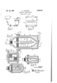
- Figure 2 isa yfront elevation of a burner
- Figure 3 is.a vertical longitudinal sectional view, of the burner takengontheline 3-3 of Figure-2; ⁇ v
- Figure 4 is a vertical transverse sectional view taken on thelineA-f-ll of Figure 3;
- Fig ure 5 isga sectiona1-,viewrthrough a modifiedformof .the mixer-burner; ⁇ and Figure .6 is a sectionallviewthrough a modified form of multi-chamber burner.
- theiflberi forming.apparat us includes generallyia glass@ melting unit I0 adapted to discharge fine streams of/ molten glassgwhich maybe attenuated .by continuouslydriven copperatingfrolls Hf to the form ofv continuous primary filaments .112.
- Attenuation of the primary filaments l2 to ne short fibers is accomplished by means of a burner l5 or name blower which is capable of producing an intensely hot gaseous blast of Very high velocity.
- the ends of the filaments are projected into the flame by the feed rolls and are substantially instantaneously melted so that the molten tips of the laments are attenuated into extremely line bers by the force of the flame or blast.
- These bers when gathered together by suitable collecting means (not shown), form a mass having a cottony or wool-like texture which may be formed into mats, bats, or rovings, or slivers from which yarns or threads may be twisted, by any conventional process.
- the combustion chamber burner of the present invention provides a substantial increase in both temperature and flame velocity so that increased production is realized as will be brought out in detail presently.
- the burner l5 as illustrated in Figure 3 of the drawings comprises a shell or casing I8 preferably formed of metal and preferably of rectangular shape, and adapted to support the burner structure therein.
- the shell is provided in one end with a slot I9 through which the burner structure dening the burner orifice projects and is open at its other end.
- Flanges 2l] at the upper and lower edges of the open end of the shell provide means by which a cup-shaped closure cap 2
- a pipe connection 23 is provided in the cap 2l to supply a highly combustible fuel through a pipe 24 to the burner from a suitable source.
- Such a fuel may be a premixed fuel gas and air
- suitable fuel gases including ordinary manufactured or natural fuel gas, methane, propane, or other readily combustible gases.
- the gas-air mixture is supplied to the burner at a pressure less than l0 pounds per square inch and preferably at pressures of from 1 to 3 pounds per square inch.
- the fuel gas-air mixture has the advantage of being readily obtainable and is more easily and safely handled than, for instance, propane or other highly compressed gases. Also, it is more economical than oxygen-acetylene when burned in sufficient volume to produce a blast having the high velocity obtainable with the gas-air mixture.
- the burner includes within the shell I8 an elongated combustion chamber 25 divided by a partition wall 26 or baille to form in effect a pair of chambers 21 and 28 or compartments communicating with a common narrow rectangular dischargeorice 3B through which the products of combustion escape.
- the partition wall 26 may be formed integral with the chamber or it may be supported when formed separately in grooves 26a provided in the side walls of the burner chamber.
- the walls forming the chambers 21 and 28 may be formed of a suitable ceramic refractory material capable of withstanding high temperatures. The life of the refractory material is extended if a liner 32 of high melting point metal is employed to cover the refractory wall as illustrated herein although the use of the liner is not necessary.
- the refractory materials from which the body of the burner may be formed are, for example, the metal oxides or carbides such as tungsten carbide, boron carbide,
- the entire burner body may be formed of one or a suitable combination of some of the above materials.
- the metallic liner 32 may be formed in any suitable way, for instance, by the powder metallurgy method of pressing nely divided metal to the proper form and then sintering the particles to consolidate them intoV an article of the desired shape.
- Tungsten and tungsten alloys are examples of high melting point metals suitable for this method of production and are adapted to withstand the temperatures approaching 4000n F.
- the metal liner may be used alone to form the chamber but since it is most economically formed rela.. tively thin it is preferable to reinforce the liner by a backing of ceramic refractory material as shown at 33, the refractory material acting also to insulate the liner from the shell I8.
- Complementary orifice plates 35 mountedvwithin the cap 2l are adapted to register with the chambers 21 and 28 and provide a uniformly distributed llow of fuel to the combustion chambers.
- the plates are preferably formed of a ceramic material and are held in place against the liner and wall members by the cap bolts 22.
- the present burner overcomes this objection to previous burners mainly by having the orifice 30 offset with respect to each chamber so that incompletely burned gas does not pass directly from the orilce plate 35 to the discharge orifice 3U. Also, higher temperatures are developed within the present burner and cause combustion rea-ction to take place more rapidly and completely.
- the products of combustion from both chambers combine at a high Velocity in the region adjacent the rear of the orifice 30 to produce an increased turbulence and mixing before the gases are discharged. Ridges 3
- the side walls of the chambers are vertical and substantially parallel while the upper and lower walls ( Figure 3) curve or taper toward each other in the direction of the orifice.
- the partition wall 26 is provided with a tapering forward edge and forms with the top and bottom walls substantially restricted passages through which the gas passes before reaching the orifice. This increases the Velocity of the products of combustion from each chamber before the two streams of gas are combined.
- the complementary converging outer walls of the passages tend to direct the ames at a substantial angle toward each other which results in the increased turbulence previously mentioned.
- An opening 36 may be provided in the partition wall liopeiated successfully'jon .;sumptionl;offabout f,prevo us burners'of/'this typefand with 4 accomplished by 'fued Apri1'27, 1944.
- bustion combustion or ceramic-materials.
- ve jiounidjthat ⁇ jthe ⁇ present-'burner may lbe '4 an increased- ⁇ fuel conabove the ⁇ maximum for ⁇ greatly 'With afuel consumption rate Yinicr'e'ast'ed results:
- Figure illustrates@ a vitirtlier VVVembcdin'lent Vof thefpresentj invention in lwhich the burner 569 comprises L; a "casing f6 I forVA supporting a burner 'As in the form of the invention shown in A Figures [l ,t0 4, the endsoffthechambers 63, 6G and ⁇ S5 are o"f decreased crcssesection'al area.
- FIG. 5 illustrates .a'niodied frmof burner V "that is also adapted to produce 'complete comof the gaseousiuel.
- Anbericht thejforrnpf a linerpf highsoftening point metal The -upper and lower walls forming .the flbergde I3 With" sectional shape of the chambers.
- V Ihe oriiicesv may ⁇ 'be round, .oval or oblong and .preferably correspondls'ubstantially to the crosstypelareuseful'when a flame of high temperature and Avelocity'Iwithinfa .localized varea are desired.
- a comhustionchamber*burner of thecharacter described [comprising a hollow shell substantially rectangular in cross section and having an .opening in one end defining a discharge orifice ,forthe productsfof vcombustion escaping from the ⁇ burner, alea p closing'theopposite end of said shell through which .a combustible fuel is supplied underlow pressure, aliner ldening a chamber withinthe shell insulated Vfrom the walls thereof and Vhaving-one ⁇ end open to the atmosphere through said-orice, the upper .and lower opposite malls of said liner .tapering toward said orifice, a
- the chamberf are shaped to create an undu lating or serpentine chamber gradually ,decreas- "in cross-sectional area Yto .a discharge orifice orport156 inthe closed end of the shell 50.
- the liner is supported within the shell by a Arefractory insulating material '5i' so that contact between the shellrand liner is prevented andheat fradiation lheld to ,a 'minimum It is also to'fbe Yunderstood that the 'combustion chamber walls "'may 'be formed entirely ofceramic'material.
- the fuel Vfn'ixi'ture is .supplied .at a relatively low vpressure ,and when ignited within the chamber expands at a high velocity and'escapes through the discharge orifice.
- the heated walls of the chamber increase the rate of ignition of thejgas.
- a burner 'hai ring Ia chamber within which a combustible mixture of gases is burned, said ve'eiiemterneving 'animetpert through which the combustible mixture of gases is introduced into the chamber and also having a discharge orifice through which the products of combustion are discharged in the form of a high temperature blast, the walls of the chamber at opposite sides of the discharge welcoming converging toward the discharge orifice, and a ⁇ Wall extending from a point adjacent the inlet port toward but short of the discharge sau and from side to side of the chamber to :partition the chamber into two compartments, the end of said wall adjacent the discharge sau being so related with respect to the opposite .converging walls of the chamber .as to form restricted outlets from the two compartments so
- a burner having ⁇ a chamber within which a combustible mixture of gases is burned
- said chamber having an inlet port through @which the combustible mixture of gases is introduced into the chamber and also having a discharge tone through which the products of combustion are discharged in the form of a high temperature bla-st, the walls of the chamber at opposite sides of the discharge réelle converging toward the discharge réelle, and a wall extending from a point adjacent the inlet port and toward but short of the ⁇ discharge orifice and from side to side of the chamber to partition the chamber into two compartments, the wall being in substantial alignment with said discharge orifice so that the compartments are offset laterally ⁇ with respect to the orifice, ywhereby the turbulence of the products of combustion :from the two compartments is increased .prior to passage of the products of combustion through said discharge orifice.
- a burner having a chamber within which a combustible mixture of gases is burned, said chamber having an inlet port through which the combustible mixture of gases is introduced into the chamber and also having a discharge oriice through ⁇ which the products of combustion are ldischarged in the :form of a high temperature blast, the opposite walls of said chamber converging toward each other adjacent said discharge orifice, and a wall extending ⁇ from the inlet port and toward but short of the discharge orifice and from side to side of the chamber to partition the chamber into two compartments, the wall being in substantial alignment with the discharge orifice and the end of said wall adjacent the discharge oriiice being so related with respect to the opposite converging lwalls of the chamber as to form restricted outlets from the two compartments, whereby the
- a burner having a plurality of combustion chambers therein, said chambers provided at one end with inlet ports through which combustible gaseous fuel is fed into the chambers to be burned therein and an exhaust orifice common to and communicating with the .other ends of said chambers 4from which orifice the stream of hot products flows, said chambers being offset laterally from said common orifice so that gases passing through said chambers .must deviate from a straight path to pass through said orifice to assure uniform lcombustion of the gases.
- a burner having a plurality of combustion chambers therein, said chambers provided at one end with inlet ports through which combustible gaseous fuel is fed into the chambers to be burned therein and an exhaust tone common to and communicating Iwith the other ends of said chambers from which perennial the stream of hot ,products flows, passages of less transverse dimensions than said chambers connecting said chambers ⁇ with said common orifice, said chambers being offset laterally from said common orifice so that gases .passing through said chambers must deviate Ifrom a straight path to pass through said orifice to assure uniform combustion of the gases.
- a burner having a plurality of combustion chambers therein, said chambers provided at one end with inlet ports through which combustible gaseous fuel is fed into the chambers and an exhaust oriiice common to and communicating with the other ends of said chambers from which sunt the stream of hot products flows, at least one of said chambers being offset laterally Ifrom said common oriice so that gases passing through said chamber must deviate from a Straight path to pass through said orifice so that any straight-line ilow ci' the gases from the chambers and through the orifice is disturbed and uniform combustion of the gases is assured.
- steps I which consist in :passing a gaseous [fuel mixture through separate highly heated zones in which it is burned, directing the products [of combustion into a common region laterally cifset lfrom said zones, thereby creating a high turbulence in said region, discharging said highly turbulent products of combustion into the atmosphere in the form of a single blast of high velocity by lwhich the rod of glass is softened and attenuated.
- a burner having a chamber ⁇ within which a combustible mixture of gases is burned, said chamber having an inlet port through which the combustible mixture of gases is introduced into the chamber and also having a discharge orifice through which the products of combustion are discharged in the form of a high temperature blast, the Walls of the chamber at opposite sides of the discharge orifice converging toward the discharge tone, a wall extending from a .point adjacent the inlet port toward but short of the discharge sau and from side to side of the chamber to partition the chamber into 10 two compartments, the end of said Wall ⁇ adjacent the discharge orifice being s0 related with respect to the opposite converging lWalls of the chamber as to ⁇ form restricted outlets Ifrom the two compartments so that the tur
Landscapes
- Engineering & Computer Science (AREA)
- Chemical & Material Sciences (AREA)
- Life Sciences & Earth Sciences (AREA)
- General Life Sciences & Earth Sciences (AREA)
- Geochemistry & Mineralogy (AREA)
- Manufacturing & Machinery (AREA)
- Materials Engineering (AREA)
- Organic Chemistry (AREA)
- Combustion & Propulsion (AREA)
- Mechanical Engineering (AREA)
- General Engineering & Computer Science (AREA)
Priority Applications (2)
| Application Number | Priority Date | Filing Date | Title |
|---|---|---|---|
| US546846A US2489244A (en) | 1944-07-27 | 1944-07-27 | Combustion chamber burner |
| FR950695D FR950695A (fr) | 1944-07-27 | 1947-07-31 | Perfectionnements aux brûleurs à chambre de combustion |
Applications Claiming Priority (1)
| Application Number | Priority Date | Filing Date | Title |
|---|---|---|---|
| US546846A US2489244A (en) | 1944-07-27 | 1944-07-27 | Combustion chamber burner |
Publications (1)
| Publication Number | Publication Date |
|---|---|
| US2489244A true US2489244A (en) | 1949-11-22 |
Family
ID=24182274
Family Applications (1)
| Application Number | Title | Priority Date | Filing Date |
|---|---|---|---|
| US546846A Expired - Lifetime US2489244A (en) | 1944-07-27 | 1944-07-27 | Combustion chamber burner |
Country Status (2)
| Country | Link |
|---|---|
| US (1) | US2489244A (fr) |
| FR (1) | FR950695A (fr) |
Cited By (18)
| Publication number | Priority date | Publication date | Assignee | Title |
|---|---|---|---|---|
| US2559504A (en) * | 1946-02-23 | 1951-07-03 | Selas Corp Of America | Gas burner with internal-combustion chambers |
| US2561194A (en) * | 1946-07-31 | 1951-07-17 | Selas Corp Of America | Internal gas burner |
| US2623579A (en) * | 1947-11-05 | 1952-12-30 | Furkert Annette | Internally fired gas burner |
| US2663906A (en) * | 1951-06-19 | 1953-12-29 | Glass Fibers Inc | Method for producing glass fibers and bonded mat |
| US2904108A (en) * | 1952-06-06 | 1959-09-15 | Selas Corp Of America | Radiant cup type gas burner |
| US2908490A (en) * | 1954-11-23 | 1959-10-13 | Westinghouse Electric Corp | Fine wire drawing furnace |
| US3044551A (en) * | 1958-12-29 | 1962-07-17 | Phillips Petroleum Co | Heater |
| US3048217A (en) * | 1956-11-21 | 1962-08-07 | Pittsburgh Plate Glass Co | Combustion chamber burner for producing glass fibers |
| US3083759A (en) * | 1957-08-13 | 1963-04-02 | Selas Corp Of America | Radiant cup gas burner |
| US3192024A (en) * | 1961-11-21 | 1965-06-29 | Pittsburgh Plate Glass Co | Method and apparatus for forming glass fibers |
| US3219425A (en) * | 1955-02-25 | 1965-11-23 | Owens Corning Fiberglass Corp | Method and apparatus for forming glass fibers |
| US3320999A (en) * | 1965-03-15 | 1967-05-23 | Owens Corning Fiberglass Corp | Internal combustion burner |
| US3363663A (en) * | 1965-06-07 | 1968-01-16 | United States Gypsum Co | Combustion chamber burner and a method for its operation |
| DE1297801B (de) * | 1965-06-23 | 1969-06-19 | Ley Friedrich | Impulskammer fuer Industriebrenner, insbesondere Gasbrenner |
| US3685946A (en) * | 1970-11-12 | 1972-08-22 | Ecological Controls Inc | Combustion chamber supplemental air supply assembly and method |
| US4878835A (en) * | 1987-09-10 | 1989-11-07 | Shell Oil Company | Ceramic burner for partial oxidation of a hydrocarbon-containing fuel |
| US5460002A (en) * | 1993-05-21 | 1995-10-24 | General Electric Company | Catalytically-and aerodynamically-assisted liner for gas turbine combustors |
| US20090297994A1 (en) * | 2005-12-21 | 2009-12-03 | Johns Manville | Burner apparatus and methods for making inorganic fibers |
Families Citing this family (2)
| Publication number | Priority date | Publication date | Assignee | Title |
|---|---|---|---|---|
| US2769791A (en) * | 1953-06-10 | 1956-11-06 | Chemstrand Corp | Composition comprising n-nitrosopiperidine and a copolymer of acrylonitrile |
| AU1862688A (en) * | 1987-07-17 | 1989-01-19 | Manville Corporation | Method and apparatus for attenuating glass fibers |
Citations (25)
| Publication number | Priority date | Publication date | Assignee | Title |
|---|---|---|---|---|
| US571076A (en) * | 1896-11-10 | Nationale des procedes adolphe seigle | ||
| US1128175A (en) * | 1912-12-02 | 1915-02-09 | Metals Coating Company Of America | Method of producing bodies or small particles of substances. |
| US1157984A (en) * | 1914-03-21 | 1915-10-26 | Metals Coating Company Of America | Method of melting and spraying fusible substances. |
| US1175224A (en) * | 1916-03-14 | Pboces of | ||
| US1328446A (en) * | 1919-01-02 | 1920-01-20 | Odam Eugene | Process and apparatus for atomizing materials in a melted state |
| US1409433A (en) * | 1921-05-23 | 1922-03-14 | Wass Joseph | Oxyacetylene blowpipe |
| GB254966A (en) * | 1925-12-01 | 1926-07-15 | Gas Turbines Ltd | Improvements relating to the production of motive fluid under pressure for power purposes |
| US1600712A (en) * | 1923-08-27 | 1926-09-21 | Bastian Blessing Co | Burner |
| US1689551A (en) * | 1925-06-02 | 1928-10-30 | William Shackleton | Gaseous-fuel burner |
| US1702642A (en) * | 1929-02-19 | Heat ceheeatoe | ||
| US1704875A (en) * | 1927-11-07 | 1929-03-12 | Surface Comb Company Inc | Method of burning gaseous mixtures |
| US1769181A (en) * | 1926-07-24 | 1930-07-01 | Jackson John Grant | Method of producing fibers from vitreous materials |
| US1822518A (en) * | 1927-08-13 | 1931-09-08 | John M Duggan | Oil burning apparatus |
| US1938982A (en) * | 1932-10-14 | 1933-12-12 | Smith Edward Wanton | Method of making glass wool separators |
| US1981976A (en) * | 1933-06-09 | 1934-11-27 | Abraham L Wem | Gas burner |
| US2015934A (en) * | 1933-04-26 | 1935-10-01 | Surface Combustion Corp | Gas burner |
| US2044511A (en) * | 1930-02-15 | 1936-06-16 | Ryschkewitsch Eugen | Burner |
| US2104311A (en) * | 1932-08-23 | 1938-01-04 | Gas Fuel Corp | Process for creating high temperatures |
| US2133235A (en) * | 1933-11-11 | 1938-10-11 | Owens Illinois Glass Co | Method and apparatus for making glass wool |
| US2228150A (en) * | 1940-03-11 | 1941-01-07 | Surface Combustion Corp | Ribbon burner |
| US2241295A (en) * | 1939-05-29 | 1941-05-06 | Partlow Corp | Safety pilot burner |
| US2269459A (en) * | 1937-08-11 | 1942-01-13 | Owens Corning Fiberglass Corp | Tubular fiber |
| US2269528A (en) * | 1940-03-30 | 1942-01-13 | Rca Corp | Method of manufacturing metal spheres |
| US2367119A (en) * | 1940-01-20 | 1945-01-09 | Selas Corp Of America | Method of and apparatus for heating |
| US2402045A (en) * | 1946-06-11 | Aet of heating |
-
1944
- 1944-07-27 US US546846A patent/US2489244A/en not_active Expired - Lifetime
-
1947
- 1947-07-31 FR FR950695D patent/FR950695A/fr not_active Expired
Patent Citations (25)
| Publication number | Priority date | Publication date | Assignee | Title |
|---|---|---|---|---|
| US571076A (en) * | 1896-11-10 | Nationale des procedes adolphe seigle | ||
| US1175224A (en) * | 1916-03-14 | Pboces of | ||
| US1702642A (en) * | 1929-02-19 | Heat ceheeatoe | ||
| US2402045A (en) * | 1946-06-11 | Aet of heating | ||
| US1128175A (en) * | 1912-12-02 | 1915-02-09 | Metals Coating Company Of America | Method of producing bodies or small particles of substances. |
| US1157984A (en) * | 1914-03-21 | 1915-10-26 | Metals Coating Company Of America | Method of melting and spraying fusible substances. |
| US1328446A (en) * | 1919-01-02 | 1920-01-20 | Odam Eugene | Process and apparatus for atomizing materials in a melted state |
| US1409433A (en) * | 1921-05-23 | 1922-03-14 | Wass Joseph | Oxyacetylene blowpipe |
| US1600712A (en) * | 1923-08-27 | 1926-09-21 | Bastian Blessing Co | Burner |
| US1689551A (en) * | 1925-06-02 | 1928-10-30 | William Shackleton | Gaseous-fuel burner |
| GB254966A (en) * | 1925-12-01 | 1926-07-15 | Gas Turbines Ltd | Improvements relating to the production of motive fluid under pressure for power purposes |
| US1769181A (en) * | 1926-07-24 | 1930-07-01 | Jackson John Grant | Method of producing fibers from vitreous materials |
| US1822518A (en) * | 1927-08-13 | 1931-09-08 | John M Duggan | Oil burning apparatus |
| US1704875A (en) * | 1927-11-07 | 1929-03-12 | Surface Comb Company Inc | Method of burning gaseous mixtures |
| US2044511A (en) * | 1930-02-15 | 1936-06-16 | Ryschkewitsch Eugen | Burner |
| US2104311A (en) * | 1932-08-23 | 1938-01-04 | Gas Fuel Corp | Process for creating high temperatures |
| US1938982A (en) * | 1932-10-14 | 1933-12-12 | Smith Edward Wanton | Method of making glass wool separators |
| US2015934A (en) * | 1933-04-26 | 1935-10-01 | Surface Combustion Corp | Gas burner |
| US1981976A (en) * | 1933-06-09 | 1934-11-27 | Abraham L Wem | Gas burner |
| US2133235A (en) * | 1933-11-11 | 1938-10-11 | Owens Illinois Glass Co | Method and apparatus for making glass wool |
| US2269459A (en) * | 1937-08-11 | 1942-01-13 | Owens Corning Fiberglass Corp | Tubular fiber |
| US2241295A (en) * | 1939-05-29 | 1941-05-06 | Partlow Corp | Safety pilot burner |
| US2367119A (en) * | 1940-01-20 | 1945-01-09 | Selas Corp Of America | Method of and apparatus for heating |
| US2228150A (en) * | 1940-03-11 | 1941-01-07 | Surface Combustion Corp | Ribbon burner |
| US2269528A (en) * | 1940-03-30 | 1942-01-13 | Rca Corp | Method of manufacturing metal spheres |
Cited By (19)
| Publication number | Priority date | Publication date | Assignee | Title |
|---|---|---|---|---|
| US2559504A (en) * | 1946-02-23 | 1951-07-03 | Selas Corp Of America | Gas burner with internal-combustion chambers |
| US2561194A (en) * | 1946-07-31 | 1951-07-17 | Selas Corp Of America | Internal gas burner |
| US2623579A (en) * | 1947-11-05 | 1952-12-30 | Furkert Annette | Internally fired gas burner |
| US2663906A (en) * | 1951-06-19 | 1953-12-29 | Glass Fibers Inc | Method for producing glass fibers and bonded mat |
| US2904108A (en) * | 1952-06-06 | 1959-09-15 | Selas Corp Of America | Radiant cup type gas burner |
| US2908490A (en) * | 1954-11-23 | 1959-10-13 | Westinghouse Electric Corp | Fine wire drawing furnace |
| US3219425A (en) * | 1955-02-25 | 1965-11-23 | Owens Corning Fiberglass Corp | Method and apparatus for forming glass fibers |
| US3048217A (en) * | 1956-11-21 | 1962-08-07 | Pittsburgh Plate Glass Co | Combustion chamber burner for producing glass fibers |
| US3083759A (en) * | 1957-08-13 | 1963-04-02 | Selas Corp Of America | Radiant cup gas burner |
| US3044551A (en) * | 1958-12-29 | 1962-07-17 | Phillips Petroleum Co | Heater |
| US3192024A (en) * | 1961-11-21 | 1965-06-29 | Pittsburgh Plate Glass Co | Method and apparatus for forming glass fibers |
| US3320999A (en) * | 1965-03-15 | 1967-05-23 | Owens Corning Fiberglass Corp | Internal combustion burner |
| US3363663A (en) * | 1965-06-07 | 1968-01-16 | United States Gypsum Co | Combustion chamber burner and a method for its operation |
| DE1297801B (de) * | 1965-06-23 | 1969-06-19 | Ley Friedrich | Impulskammer fuer Industriebrenner, insbesondere Gasbrenner |
| US3685946A (en) * | 1970-11-12 | 1972-08-22 | Ecological Controls Inc | Combustion chamber supplemental air supply assembly and method |
| US4878835A (en) * | 1987-09-10 | 1989-11-07 | Shell Oil Company | Ceramic burner for partial oxidation of a hydrocarbon-containing fuel |
| US5460002A (en) * | 1993-05-21 | 1995-10-24 | General Electric Company | Catalytically-and aerodynamically-assisted liner for gas turbine combustors |
| US20090297994A1 (en) * | 2005-12-21 | 2009-12-03 | Johns Manville | Burner apparatus and methods for making inorganic fibers |
| US8192195B2 (en) * | 2005-12-21 | 2012-06-05 | Johns Manville | Burner apparatus and methods for making inorganic fibers |
Also Published As
| Publication number | Publication date |
|---|---|
| FR950695A (fr) | 1949-10-04 |
Similar Documents
| Publication | Publication Date | Title |
|---|---|---|
| US2489244A (en) | Combustion chamber burner | |
| US2489242A (en) | Method and apparatus for making fine glass fibers | |
| US2609566A (en) | Method and apparatus for forming fibers | |
| US1910735A (en) | Burner for coal dust firing | |
| US2367119A (en) | Method of and apparatus for heating | |
| US2515738A (en) | Apparatus for producing glass fibers | |
| US2578101A (en) | Apparatus for producing fibers from glass and other heat softenable materials | |
| US2614619A (en) | Burner and nozzle tip for projecting hot products of combustion | |
| US2443707A (en) | Hot-air heater with fuel vaporizer and air mixer | |
| US3320999A (en) | Internal combustion burner | |
| US2561200A (en) | Internal gas burner | |
| US3084525A (en) | Manufacture of fibers from thermoplastic material, particularly glass fibers | |
| US2140316A (en) | Apparatus for converting hydrocarbons | |
| US2578100A (en) | Method and apparatus for forming fibers | |
| US3879530A (en) | Method for the combustion of sulphur | |
| US3045278A (en) | Fiber forming torch | |
| US3015842A (en) | Apparatus for producing fibers | |
| US4060380A (en) | Furnace having burners supplied with heated air | |
| US3936275A (en) | Apparatus for the combustion of sulphur | |
| US2569699A (en) | Method and apparatus for forming glass fibers | |
| US2625795A (en) | Combustion stabilization means for high-velocity air streams having a pilot burner and a streamline igniter grill | |
| US2876831A (en) | Internal-combustion burners | |
| US3012281A (en) | Method of forming fibers | |
| US2402045A (en) | Aet of heating | |
| US3219425A (en) | Method and apparatus for forming glass fibers |