US2489657A - Musical instrument with tensioned strings - Google Patents
Musical instrument with tensioned strings Download PDFInfo
- Publication number
- US2489657A US2489657A US540794A US54079444A US2489657A US 2489657 A US2489657 A US 2489657A US 540794 A US540794 A US 540794A US 54079444 A US54079444 A US 54079444A US 2489657 A US2489657 A US 2489657A
- Authority
- US
- United States
- Prior art keywords
- string
- frets
- fret
- musical instrument
- tensioned
- Prior art date
- Legal status (The legal status is an assumption and is not a legal conclusion. Google has not performed a legal analysis and makes no representation as to the accuracy of the status listed.)
- Expired - Lifetime
Links
- 230000007246 mechanism Effects 0.000 description 13
- 238000005096 rolling process Methods 0.000 description 7
- 230000000694 effects Effects 0.000 description 3
- 229910000831 Steel Inorganic materials 0.000 description 2
- 239000011435 rock Substances 0.000 description 2
- 239000010959 steel Substances 0.000 description 2
- 241000538562 Banjos Species 0.000 description 1
- 101100379079 Emericella variicolor andA gene Proteins 0.000 description 1
- 240000008042 Zea mays Species 0.000 description 1
- 235000005824 Zea mays ssp. parviglumis Nutrition 0.000 description 1
- 235000002017 Zea mays subsp mays Nutrition 0.000 description 1
- 230000004308 accommodation Effects 0.000 description 1
- 235000005822 corn Nutrition 0.000 description 1
- 210000005069 ears Anatomy 0.000 description 1
- 239000002184 metal Substances 0.000 description 1
- 238000000034 method Methods 0.000 description 1
- 230000000153 supplemental effect Effects 0.000 description 1
- 239000002023 wood Substances 0.000 description 1
Images
Classifications
-
- G—PHYSICS
- G10—MUSICAL INSTRUMENTS; ACOUSTICS
- G10D—STRINGED MUSICAL INSTRUMENTS; WIND MUSICAL INSTRUMENTS; ACCORDIONS OR CONCERTINAS; PERCUSSION MUSICAL INSTRUMENTS; AEOLIAN HARPS; SINGING-FLAME MUSICAL INSTRUMENTS; MUSICAL INSTRUMENTS NOT OTHERWISE PROVIDED FOR
- G10D1/00—General design of stringed musical instruments
- G10D1/04—Plucked or strummed string instruments, e.g. harps or lyres
- G10D1/05—Plucked or strummed string instruments, e.g. harps or lyres with fret boards or fingerboards
- G10D1/08—Guitars
-
- G—PHYSICS
- G10—MUSICAL INSTRUMENTS; ACOUSTICS
- G10D—STRINGED MUSICAL INSTRUMENTS; WIND MUSICAL INSTRUMENTS; ACCORDIONS OR CONCERTINAS; PERCUSSION MUSICAL INSTRUMENTS; AEOLIAN HARPS; SINGING-FLAME MUSICAL INSTRUMENTS; MUSICAL INSTRUMENTS NOT OTHERWISE PROVIDED FOR
- G10D3/00—Details of, or accessories for, stringed musical instruments, e.g. slide-bars
- G10D3/06—Necks; Fingerboards, e.g. fret boards
Definitions
- This invention relates to musical instruments
- the pitch is determined by operation of the lingers on the strings, to determine the free vibrating lengths.
- the string can be stopped only at a series of predetermined, spaced points. It may however be desirable continuously to vary the point where the string is stopped, as for example, when playing the Hawaiian steel guitar. In this way, the pitch produced by the string is correspondingly varied through a continuous series of values.
- This invention possesses many other advantages, and has other objects which may be made more clearly apparent from a consideration of one Y string (see also Fig. 3).
- Figure 1 is a top plan view of an instrument incorporating the invention
- Fig. 2 is an enlarged sectional view, taken along plane 2 2 of Fig. 1, the central portion of the instrument being broken away to reduce the size of the figure;
- Figs. 3 and 4 are sectional views, stillfurther enlarged, taken respectively along planes 3 3 and 4 4 of Fig. 2;
- Fig. 5 is a sectional view, taken along plane 5 5 of Fig. 2;
- Fig. 6 is an enlarged fragmentary view, corresponding to a portion of Fig. 2, illustrating the manner in which the frets may be operated;
- Fig. 7 is a view similar to Fig. 6, but illustrating another phase of operation of the device
- Figs. 8 and 9 are sectional views, taken respectively along planes 8 8 and 9 9 of Fig. 7
- Fig. 10 is a plan View, partly in section, of that I portion of the structure illustrated in Fig. "i, some of the frets being removed for clarity;
- Fig. 11 is a pictorial View of one of the frets utilized in the instrument.
- a body I that serves as a convenient support for all of the parts of the instrument.
- This body may be made of wood; and, since electrical pickup devices are utilized for responding to the string vibrations, it is not necessary that this body have resonant qualities.
- strings 2, 3, 4 and 5 Stretched along the length of the body l are a number of strings 2, 3, 4 and 5. The righthand ends of these strings (Figs. 1 and 2) are disposed over a stationary bridge 6. These ends extend downwardly through appropriate apertures 1. The ends of the strings are shown as knotted, as indicated at 9. Each of the knots 9 is accommodated in a corresponding enlarged recess 8, which forms a shoulder around the aperture 'I to provide a seat for the knot.
- each string is likewise supported upon a bridge structure.
- a post l0 is provided for each Each post may be in the form of a round head screw, providing a slot li'--a in which the corresponding string may rest.
- the height of the posts is adjustable, as by 'being threaded into the top of the metallic supporting plate I3. Lock nuts I4 may be used to maintain the adjustment.
- the pin 'II may be turned in the well understood manner, as by the aid of a tuning peg I2.
- An electric pick-up device jI5o'i1any well-known type may be arranged adjacent the bridge 6 for transmitting electrical vibrations in accordance with the string vibrations.
- the mechanism for adjusting the free vibrating length of any of theistrings as desired by the player is located mainly in the recess I5 formed in the body I. Since the mechanisms for all of. the strings are substantially identical, it is necessary merely to describe in. detail the mechanism associated with one of these strings, such as. string 5.
- each of the stringsv Arranged in regular order below each of the stringsv are a series. of movable frets. Some of the frets associated'with string 5, are shown in Fig. 2, and are indicated by reference characters I'I to 22 inclusive. These frets are confined within a longitudinalv slot '23, in theA plate i3 underneath the corresponding string (see, especially Figs. 4, 8 and 9).. Each ofthe frets has a con.- vex string engaging surface2j'4 l(Figs. 6, 7 and 8). The string 5, when the 'frets are movedupwardly, thus. touches the. convex ⁇ surface 24 at a point such as 25 (Fig. '1).
- the fretsY are furthermore arranged to be'rocked'in successionin such manner that the point ofcontactY 2.5'oi the string. 5 with the convex string engaging surface 24 can move in a continuous manner from one .end of' the conyexsurface to the other. Thence a succeeding fret cornes ⁇ into contact with the string, and the process is repeated.
- Fig. rrI', fret. IScan rock to the position of Fig. 6; andv nowv the succeedingA fret 26 is in position to :b e contacted by string 5.
- This fret may now be rocked to move the Vpoint of contact from leit to rightY along Athe convex surface 24 cf fret 20. This gliding or undulating motion of the frets simulates quite closely the effectV obtained Ain the -playi-ngof the Hawaiian guitar by moving a steel rod along Ythe string.
- 'Overhanging 'the iianges 2-6 are the plates 21' and 28, -shown to best advantage in Fig. 4.
- Supplemental plates 29, 30, andA 3l cooperate with the frets thata-re disposedbeneath the other strings, '4, 3', andf2.
- Theend plates '21 and 3I are associated with theend slots 23 and 32.
- All yofl the plates 21, 28, 29, 36, and 3l are shown in Figs. -1 as being attached to the supportingV plate I3 by the aid of the metallic -flat head screws'33; These-plates 21, 218, 29, 30, Vand 3! are eachvprov-ided with-transverse markings III) spacedA invsuchV :manner lthat their position
- the intermediate plates 28', '29, and 36 VhaveA their opposite edgesv extending over adjacent 4 indicates the tone obtained when a string is stopped at a point corresponding to the position of one of the markings.
- the flange 26 and the lower pointed edge 40 of the projection 39 are arcuate, and concentric with the string contacting surface 24 of the fret. Furthermore, the frets are jointed or hinged as by the aid of cylindrical projections 4I extending from their left-hand faces, and near the top ofthe frets. These projections t into corresponding cylindrical sockets 42 in the adjacent fret. As shown most clearly in Figs. 6 and 7, the converging sides 44 of thev frets .permit freedom of relative angular motion at the hinges. Above the hingesl the sides of the fret are spaced apart, as indicated by the boundary planes 43. In this. way, a complete articulation about the hinge axis. is permitted.
- the extremel left-hand fret I1 for each. string is in. the elevated position indicated inY Fig. 2.
- Thev left-hand side of this fret is curved to move smoothly with respect to the end wall of the slot.y in which the fret is accommodated.
- the right-hand end fret 22 is also pro-- vided with a curved right-hand side.
- the slot.. 23 in the supporting plate .I3 is justlong enough to permit the undulating motionto take place.. with inappreciable clearance between the hingesV elements.
- a cam-like member 45 (Figs. 2, Yand 4 to 10 inclusive).
- This camlike member 45 may most conveniently be in the, form of a rod having a helical-like crest .46,.and; having an axis ,of rotation substantially parallel. with the length of string 5.
- Crest 46 extends in. ⁇ a helical manner about the axis of the rod.. making about three-quarters of a revolution.
- the rod 45 is rotated about its axis, the helicallike crest 46 contacts the lower. edges 40v of the frets in succession.
- an undulating motion is provided where the crest 46 isin contact with an edge 46. This undulatingV motion may be best explained in connection with Figs. 6, 1,8, 9,.and 10.
- Crested rods 50, 5I, and 52, parallel with rod 45, are disposed underneath the slots 32, 54, and 55 that accommodate the frets cooperating with strings 2, 3, 4, and 5 (see especially Fig. 4). These rods operate the respective frets in a manner described in connection with rod 45.
- Rod is shown as rotatably supported at its right-hand end by the aid ofthe stub shaft 56 that is journalled in a bracket 51.
- This bracket 51 extends transversely to the recess I6, and is supported beneath the supporting plate I3. In this way, the bracket 51 can serve to support rotatably all of the rods 45, 50, 5I, and 52.
- bracket 59 Similar to bracket 56, rotatably supports the stub shaft 60 projecting from the lefthand end of the cylindrical portion 58. Adjacent the right-hand end of the cylindrical portion 58, as viewed in Fig. 2, another bracket 6
- rod 45 Operation of rod 45 is obtained by the aid oi' a rack and pinion mechanism.
- the rack 69 is carried by a key 62 (Figs- 1, 2, 3, and 5). This rack meshes with a pinion 10 carried by cylindrical extension 58.
- Key 62 has a flat operating portion extending transversely of the axis of rod 45, and has a downwardly extending portion 63 capable of being manipulated by one of the iingers of the player.
- the key is guided at its side edges by the aid of guide bars 64 and 65 located at the right of the device, as shown in Fig. 2, and by the corresponding guide bars 66 (Fig. 3) at the left-hand end of the key 62.
- Guide bars 64 and 65 may be found integral with a flange 1I, fastened to the bottom of plate I3.
- Guide bars 66 are likewise formed integrally with a flange 61 that is extended to form a cover for the space 68.
- This space is a transverse extension of space I6 to accommodate the ends of the operating keys Since the lower edge whenthe'y are urged toward the left, as viewed in Fig. 3. Similarly, space I6 is extended to the right-hand edgeof the instrument, as viewed in Fig. 3, where the operating ends 63 of the keys are located to permit inward motion of the keys.
- By moving the key 62 inwardly, or toward the left, as viewed in Fig. 3, counter-clockwise rotation is imparted to the rod 45, due to rotation of pinion 18 by rack 69. The extent of movement determines the angular position of the helicallike crest 46, and the corresponding point where the crest is in contact with one of the series of frets.
- the upper surface of the key 62 may carry the stops 12 and 13 to limit the linear movement of the rack 69. These co-operate with the guide plates 64, 65, and 66. Furthermore, a resilient means is provided for urging the rack 69 and the key 62 toward the right, corresponding to the starting position where stop 13 is in contact with plates 64, 65. In this position, the extreme lefthand fret I1 is the one that is raised, as indicated in Fig. 2.
- the resilient means comprises a coil spring 14 (Figs. 2 and 5) disposed over extension 58. One end of this coil spring is anchored in the bracket 6
- the force of the spring may be adjusted by appro- ⁇ priate angular adjustment of the collar 15. This force is in such a direction as to tend to move the rod 45 in clockwise direction, as viewed in Fig. 3.
- keys 16, 11, and 18 are utilized to operate the rods 52, 5
- Each of these keys is guided similarly to key 62 by downwardly extending guide plates 65, 83, 84, and joined to flange 1
- Each of the rods ⁇ 52, 5I, and 58 carries a pinion indicated by reference characters 19, 8
- 88 are utilized to urge the rods 52, 5
- 66 is shown as anchored in the bracket 6
- , and 52 may be manipulated to cause the desired undulating motion of the corresponding frets associated with the tensioned strings.
- an adjustable lever mechanism is indicated in Figs. 1, 2, and 5.
- This lever has a horizontal portion 81, as seen in Fig. 2. Its vertical portion can move with respect to the body I in a slot 88 formed in the body I.
- Lever 86 is pivoted on a boss 89 mounted in the recess 90 communicating with the recess I6.
- is pivoted.
- This link is joined to a crank arm 92V that serves to operate a control rheostat 93,61-A the like, disposed in a recess 94 of the'body I. f
- a sheet metal cover v95 (Figs. 1, 2, and 3) is pro.- vicled at the left-hand end of the instrument for covering the mechanism at that end.
- the cover is detachably supported in a. manner now to be described.
- the cover 95 includes a pair of side flanges 96 and
- the right-hand end of the cover is also provided with a iiange 91, formed integrally with flanges '9S and
- the left-hand edge 99 of the plate I3 is arcuate, as indicated in Figs. 1 and 2.
- Flanges 9B and 09 have portions IOI and
- ⁇ extensions Ii and IIlI form virtually a strap-like clamp over the left-hand end of plate I3.
- these extensions and Il may be formed with ears
- 00, and lill are closely clamped to the side ed-ges of the support I3.
- the cover member 95 may be readily removed, if desired, by loosening screw.
- each fret in a musical instrument having a tensioned string, a plurality of frets movable relative to each other, each fret having an arched surface engageably mounted with said tensioned string and y means for moving the frets to cause Asaid surfaces to contact the string progressively along said surfaces.
- each fret having an arched surface, said surfaces engageably mounted with said ten sioned string, and an operating member having a cam portion for moving the frets to produce a rolling contact between the fret .surface and the string.
- each fret havin-g an arched surface en.- gageably mounted with said tensioned string means for guiding the movement ofthe frets to ward and away from the string, and a mechanism for imparting a rolling motion to the lfret surface upon the string.
- a movable fret having an arched surface, means for guiding the movement of the fret to-4 ward and away vfrom the string, and a mecha-A nism for imparting a rolling motion to vthe fret surface v.upon the string, sa-idmechanism includ-v ing a rotary rod having a helical-like crest that' cooperates with ⁇ a portion of the fret.
- a fret having a convex string engaging surface
- means forming a guide for the fret means for moving the fretto cause contact between the surface and the string, and means providing an axis of motion for the fret transverse to the string.
- a fret having a convex string engaging surface
- means forming a guide for the fret means for moving the fret to cause contact between the surface and the string, and means providing a shifting axis for the fret, transverse to the string, and shifted toward the string as the fret is operated by the fret moving means.
- a fret having a convex string engaging surface, means forming a shifting axis for the fret, transverse to the string, and means for imparting an angular motion, as well asa motion of translation, to the fret for urging the fret toward the ⁇ string and for varying the point of contact between the string and the surface.
- a fret having a convex string engaging surface, means forming a shifting axis for the fret, transverse to the string, and means for imparting an angular motion, as well as a motionY of translation, to the fret for urging the fret toward the string and for varying the point of contactbetween the string and the surface, comprising a crested rod engaging the fret on a surface disposed opposite the convex surface.
- Va fret having a convex string engaging surface, means forming a shifting axis for the fret, transverse to the string, and means for imparting an angular motion, as Well as a motion of translation, to the fret for urging the fret toward the string and for varying the point of contact between the string and the surface, comprising a rotatable rod having a crest contacting a concave surface of the fret.
- a fret having a convex string engaging surface, means forming a shifting axis for the fret, transverse to the string, and means for imparting an angular motion, as well as a motion of translation, to the fret for urging the fret toward the string and for varying the point of contact between the string and the surface, said fret having a concave surface adapted tobe contacted by said motion imparting means.
- a musical instrument having a tensioned string', -a fret having a convex string engaging surface, means forming a shifting axis for the fret, transverse tothe string, and means for imparting an angular motion, as well as a motion of translation, to the 'fret for urging the fret toward the string and for varying the point of contact between the string and the surface, comprisi-ng a movable member having a cam-like crest, said crest havin-g side surfaces, a point of the crest' contacting a concavesurface of the fret, said concave surface crossing the crest at said point and having portions conforming to the sides of the crest, motion of the rotatable mem- -ber causing the point of contact between the crest and the concave surface.
- a musical instrument having a tensioned string, a guide member, a series of frets guided therein and extending in a direction lengthwise of the string, adjacent frets being jointed together, each of the frets having a convex string engaging surface, and means for successively operating the frets to cause them to engage the string at a point that progresses along said surface.
- a musical instrument having a tensioned string, a guide member, a series of frets guided therein and extending in a direction lengthwise of the string, adjacent frets being jointed tgether, each of the frets having a convex string engaging surface, and means for rocking any of the frets to cause the string to contact a surface in a progressively continuous manner, comprising a rotatable rod having an axis of rotation substantially parallel to the string and having a raised crest for successively operating the frets.
- a musical instrument having a tensioned string, a guide member, a series of frets guided therein and extending in a direction lengthwise of the string, adjacent frets being jointed together, each of the frets having a convex string engaging surface, and means for rocking any of the frets to cause the string to contact a surface in a progressively continuous manner, comprising a rotatable rod having a helical-like crest that successively operates the frets.
- each fret having a convex string engaging surface, and means for rocking any of the frets to cause the string to contact a surface in a progressively continuous manner, each fret having a concave surface that is intersected by the crest during operation of the fret, the concave surface contacting the sides of the crest.
- a musical instrument having a tensioned string, a plurality of frets, means supporting said frets for lmovement relative to each other into and out of engagement with said string, and means for moving said frets successively into engagement with said string so that the contact point between the frets and string moves in a continuous manner along the length of the string.
- a musical instrument having a tensioned string, a plurality of frets arranged generally in a common central plane, means supporting said frets for movement relative to each other into and out of engagement with said string, and means for moving ⁇ saidl frets successively into engagement with said string so that the contact point between the frets and string moves in a continuous manner along the length of the string.
- a movable fret having an arched surface, means for guiding the fret for movement toward and away from the string, and a mechanism for imparting a rolling motion to the fret surface upon the string, said mechanism including a rotary rod movable relative to said fret and having a helical-like crest that cooperates with a portion of the fret.
Landscapes
- Physics & Mathematics (AREA)
- Engineering & Computer Science (AREA)
- Acoustics & Sound (AREA)
- Multimedia (AREA)
- Electrophonic Musical Instruments (AREA)
Description
Nov, 29, 1949 J. w. MCBRIDE MUSICAL INSTRUMENT WITH TENSIONED STRINGS 3 Sheets-Sheet l Filed June 17, 1944 Nov. 29, 1949 .J.^w. MCBRIDE 2,489,657
MUSICAL INSTRUMENT WITH TENSIONED STRINGS Filed June 17, 1944 s sheets-smeet 2 \N\JENTOR Jo/m W M65/7U? Nov. 29, 1949 J. w. MCBRIDE 2,489,657
MUSICAL INSTRUMENT WITH TENSIONED STRINGS Filed June 17, 1944 3 Sheets-Sheet 3 xNvENToR BY n/ivm ATTORNEY Patented Nov. 29, 1949 MUSICAL INSTRUMENT WITH TENSIONED STRINGS John W. McBride, Burbank, Calif., assigner to Bantar, Incorporated, Burbank, Calif., a corporation of California Application June 17, 1944, Serial No. 540,794
22 Claims.
This invention relates to musical instruments,
and particularly those with tensioned strings.
' In a conventional instrument of this kind, such as a violin, guitar, banjo, or mandolin, the pitch is determined by operation of the lingers on the strings, to determine the free vibrating lengths.
A mechanism for effecting stopping of the strings by mechanical means is described and claimed in an application filed on March 16, 1942, under Serial No. 434,855, in the name of John W. McBride and entitled: Stringed musical instrument, now Patent No. 2,368,256 issued January 30, 1945. In that application, the adjustment in the free vibrating length is accomplished by the aid of movable frets, any one of which may be urged upwardly into contact with the corresponding string. The frets for each string are operated by a cam device, or the like.
It is a consequence resulting from the use of such a device as described in said prior application, that the string can be stopped only at a series of predetermined, spaced points. It may however be desirable continuously to vary the point where the string is stopped, as for example, when playing the Hawaiian steel guitar. In this way, the pitch produced by the string is correspondingly varied through a continuous series of values.
It is one of the objects of this invention to make it possible to operate a series of movable frets so as to vary in a continuous manner the point of Contact of the frets with the corresponding string.
To effect this result, that surface of the fret which is intended to contact the string is arched, and the fret is so operated as to bring diiferent parts of that surface into contact by an action similar to a rolling action.
It is another object of this invention to make it possible to produce this rolling action, and especially by the aid of simple and inexpensive structures.
It is still another object of this invention to ensure that frets, as they become successively active, produce an undulating or rolling effect, the string being contacted by a wave-like motion of the frets. Thus, substantially smooth continuity of operation is assured between maximum and minimum free string lengths, as the frets are operated in succession.
It is still another object of this invention to provide generally an improved musical instrument of the character above specified.
This invention possesses many other advantages, and has other objects which may be made more clearly apparent from a consideration of one Y string (see also Fig. 3).
embodiment of the invention. For this purpose there is shown a form in the drawings accompanying and forming part of the present specification. The form will now be described in detail, illustrating the general principles of the invention; but it is to be understood that this detailed description is not to be taken in a limiting sense, since the scope of this invention is best defined by the appended claims.
Referring to the drawings:
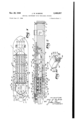
Figure 1 is a top plan view of an instrument incorporating the invention;
Fig. 2 is an enlarged sectional view, taken along plane 2 2 of Fig. 1, the central portion of the instrument being broken away to reduce the size of the figure;
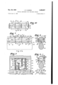
Figs. 3 and 4 are sectional views, stillfurther enlarged, taken respectively along planes 3 3 and 4 4 of Fig. 2;
Fig. 5 is a sectional view, taken along plane 5 5 of Fig. 2;
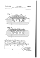
Fig. 6 is an enlarged fragmentary view, corresponding to a portion of Fig. 2, illustrating the manner in which the frets may be operated;
Fig. 7 is a view similar to Fig. 6, but illustrating another phase of operation of the device;
Figs. 8 and 9 are sectional views, taken respectively along planes 8 8 and 9 9 of Fig. 7
Fig. 10 is a plan View, partly in section, of that I portion of the structure illustrated in Fig. "i, some of the frets being removed for clarity; and
Fig. 11 is a pictorial View of one of the frets utilized in the instrument.
As shown most clearly in Figs. 1 and 2, a body I is provided that serves as a convenient support for all of the parts of the instrument. This body may be made of wood; and, since electrical pickup devices are utilized for responding to the string vibrations, it is not necessary that this body have resonant qualities.
Stretched along the length of the body l are a number of strings 2, 3, 4 and 5. The righthand ends of these strings (Figs. 1 and 2) are disposed over a stationary bridge 6. These ends extend downwardly through appropriate apertures 1. The ends of the strings are shown as knotted, as indicated at 9. Each of the knots 9 is accommodated in a corresponding enlarged recess 8, which forms a shoulder around the aperture 'I to provide a seat for the knot.
The left-hand portion of each string is likewise supported upon a bridge structure. In the present instance, a post l0 is provided for each Each post may be in the form of a round head screw, providing a slot li'--a in which the corresponding string may rest. The height of the posts is adjustable, as by 'being threaded into the top of the metallic supporting plate I3. Lock nuts I4 may be used to maintain the adjustment.
After the string passes through the slot formed in the headY of the corresponding post, itis uien wound around ,a pin, such as II illustrated in,
Fig. 1. The pin 'II may be turned in the well understood manner, as by the aid of a tuning peg I2.
By providing an adjustablepost Il)4 for each of the strings, their position relative to the body l may be accurately determined.
An electric pick-up device jI5o'i1any well-known type may be arranged adjacent the bridge 6 for transmitting electrical vibrations in accordance with the string vibrations.
The mechanism for adjusting the free vibrating length of any of theistrings as desired by the player is located mainly in the recess I5 formed in the body I. Since the mechanisms for all of. the strings are substantially identical, it is necessary merely to describe in. detail the mechanism associated with one of these strings, such as. string 5.
Arranged in regular order below each of the stringsv are a series. of movable frets. Some of the frets associated'with string 5, are shown in Fig. 2, and are indicated by reference characters I'I to 22 inclusive. These frets are confined within a longitudinalv slot '23, in theA plate i3 underneath the corresponding string (see, especially Figs. 4, 8 and 9).. Each ofthe frets has a con.- vex string engaging surface2j'4 l(Figs. 6, 7 and 8). The string 5, when the 'frets are movedupwardly, thus. touches the. convex` surface 24 at a point such as 25 (Fig. '1). 'The fretsY are furthermore arranged to be'rocked'in successionin such manner that the point ofcontactY 2.5'oi the string. 5 with the convex string engaging surface 24 can move in a continuous manner from one .end of' the conyexsurface to the other. Thence a succeeding fret cornes `into contact with the string, and the process is repeated. Thus from the position of Fig. rrI', fret. IScan rock, to the position of Fig. 6; andv nowv the succeedingA fret 26 is in position to :b e contacted by string 5. This fret may now be rocked to move the Vpoint of contact from leit to rightY along Athe convex surface 24 cf fret 20. This gliding or undulating motion of the frets simulates quite closely the effectV obtained Ain the -playi-ngof the Hawaiian guitar by moving a steel rod along Ythe string.
The manner in W-hichuthe Iundulating motion of theseriesoffrets-"11, etc. is obtained will now be described.
Each of the frets -associa-tediwith string 51s restrained ior movement transversely-of the guide slot 23`by Yhavingitssidedianges26 (Figs. 6, 2, 8, and 11) in sliding contact with the sides ci the slot 23. 'Overhanging 'the iianges 2-6 are the plates 21' and 28, -shown to best advantage in Fig. 4. Supplemental plates 29, 30, andA 3l cooperate with the frets thata-re disposedbeneath the other strings, '4, 3', andf2. Theend plates '21 and 3I are associated with theend slots 23 and 32.
slots. All yofl the plates 21, 28, 29, 36, and 3l are shown in Figs. -1 as being attached to the supportingV plate I3 by the aid of the metallic -flat head screws'33; These-plates 21, 218, 29, 30, Vand 3! are eachvprov-ided with-transverse markings III) spacedA invsuchV :manner lthat their position The intermediate plates 28', '29, and 36 VhaveA their opposite edgesv extending over adjacent 4 indicates the tone obtained when a string is stopped at a point corresponding to the position of one of the markings.
The plates 21, 28, 29, 30, and 3| eiectively restrict upward movement of all of the frets. Downward movement is restrained by corresponding plates 34,. .3.5, 36, 31, and 3.8.. These plates are spaced apartfsufciently to ,guideY the narrow extensions 39 projecting beneath each of the frets, and shown most clearly in Figs. 4, 8, 9, and 11.
The flange 26 and the lower pointed edge 40 of the projection 39 are arcuate, and concentric with the string contacting surface 24 of the fret. Furthermore, the frets are jointed or hinged as by the aid of cylindrical projections 4I extending from their left-hand faces, and near the top ofthe frets. These projections t into corresponding cylindrical sockets 42 in the adjacent fret. As shown most clearly in Figs. 6 and 7, the converging sides 44 of thev frets .permit freedom of relative angular motion at the hinges. Above the hingesl the sides of the fret are spaced apart, as indicated by the boundary planes 43. In this. way, a complete articulation about the hinge axis. is permitted.
Normally,.when the instrument is inactive, the extremel left-hand fret I1 for each. string is in. the elevated position indicated inY Fig. 2. Thev left-hand side of this fret is curved to move smoothly with respect to the end wall of the slot.y in which the fret is accommodated. For like reasons, the right-hand end fret 22 is also pro-- vided with a curved right-hand side. The slot.. 23 in the supporting plate .I3 is justlong enough to permit the undulating motionto take place.. with inappreciable clearance between the hingesV elements.
.Operation of thefrets to raise andl rock them in succession is provided` by a cam-like member 45 (Figs. 2, Yand 4 to 10 inclusive). This camlike member 45 may most conveniently be in the, form of a rod having a helical-like crest .46,.and; having an axis ,of rotation substantially parallel. with the length of string 5. Crest 46 extends in.` a helical manner about the axis of the rod.. making about three-quarters of a revolution. As` the rod 45 is rotated about its axis, the helicallike crest 46 contacts the lower. edges 40v of the frets in succession. As the rotation continues,V an undulating motion is provided where the crest 46 isin contact with an edge 46. This undulatingV motion may be best explained in connection with Figs. 6, 1,8, 9,.and 10.
In the position vof Figs. 1 and 10, the helicallikecrest `46 is incontact with the center of the. lower edge 46 associated.-.with the fret I9. In thisI position, the center of. the convex -surface 24 contacts the string 5. The point of` contact between `crest45 and the edge 40 is illustrated .by reference character 41 in Fig. 1. The crest 4B crosses the lower edge 4D at point 41, as illustrated'most clearly in Fig. 10. rThus, toward the, right of the point 41, the crest ,46"is back of the edge 46 (see also Fig. 9). Toward theleft of the point .41, the crest 46 is infront of the edge 40; The sides 48 and 49 (Figs. '8 and 9) of the member 45' can be so shaped that the edge 46 stays in substantial Contactv with these sides while the crest 46 is in operative relation with the fret. Contact between the side 48 andthe lower edge 49'is indicated inFig. 9.
Now, as the rod 45 is rotated in one ,or the other direction from that illustrated 'in' Fig. 7, the-fret I9 is rocked and the hingesbetween the frets are moved in a direction transverse to string 5. Accordingly, the contact point moves either to the right or left. Y
Thus, as indicated in Fig. 6, if the rod 45 is moved from the position of Fig. 7 angularly about its axis so that the crest 46 just touches the righthand edge of the fret I9, then this fret has been correspondingly rocked or rotated in a counterclockwise direction about the hinge formed between the fret I9 and fret 20. At the same time, the hinge between these frets has been raised, and fret 20 has been rotated in a clockwise direction about the hinge. Continued movement of the crest 46 toward the right, as viewed in Fig. 6, will cause the point of contact with the string 5 to occur on fret 20; and it will continue on fret 20 until the crest 46 reaches the lower right-hand corner of fret 20.
The successive rocking of the crests with corresponding raising and lowering of the hinges is characteristic of the motion imparted to the frets by rotation of the rod 45. contacts the sides 48, 49 that join to form the crest 46, the rocking or undulating motion of the crest is accomplished by positive contact of a substantial portion of the crest with the hinges.
Crested rods 50, 5I, and 52, parallel with rod 45, are disposed underneath the slots 32, 54, and 55 that accommodate the frets cooperating with strings 2, 3, 4, and 5 (see especially Fig. 4). These rods operate the respective frets in a manner described in connection with rod 45. Rod is shown as rotatably supported at its right-hand end by the aid ofthe stub shaft 56 that is journalled in a bracket 51. This bracket 51 extends transversely to the recess I6, and is supported beneath the supporting plate I3. In this way, the bracket 51 can serve to support rotatably all of the rods 45, 50, 5I, and 52.
At its left-hand end the rod 45 is provided with a cylindrical extension 58 (Figs. 2, 3, and 5). A bracket 59, similar to bracket 56, rotatably supports the stub shaft 60 projecting from the lefthand end of the cylindrical portion 58. Adjacent the right-hand end of the cylindrical portion 58, as viewed in Fig. 2, another bracket 6| is provided in which the cylindrical extension 58 is journalled. Both brackets 59 and 6I are wide enough to accommodate all of the other rods 50, 5I, and 52.
Manual operation of the rods is obtained by keys 62, 16, 11, and 18, arranged side by side. Since the key mechanisms are similar, a description of the mechanism associated with rod 45 will serve as descriptive of all of them.
Operation of rod 45 is obtained by the aid oi' a rack and pinion mechanism. The rack 69 is carried by a key 62 (Figs- 1, 2, 3, and 5). This rack meshes with a pinion 10 carried by cylindrical extension 58.
Key 62 has a flat operating portion extending transversely of the axis of rod 45, and has a downwardly extending portion 63 capable of being manipulated by one of the iingers of the player. The key is guided at its side edges by the aid of guide bars 64 and 65 located at the right of the device, as shown in Fig. 2, and by the corresponding guide bars 66 (Fig. 3) at the left-hand end of the key 62. Guide bars 64 and 65 may be found integral with a flange 1I, fastened to the bottom of plate I3. Guide bars 66 are likewise formed integrally with a flange 61 that is extended to form a cover for the space 68.
This space is a transverse extension of space I6 to accommodate the ends of the operating keys Since the lower edge whenthe'y are urged toward the left, as viewed in Fig. 3. Similarly, space I6 is extended to the right-hand edgeof the instrument, as viewed in Fig. 3, where the operating ends 63 of the keys are located to permit inward motion of the keys. By moving the key 62 inwardly, or toward the left, as viewed in Fig. 3, counter-clockwise rotation is imparted to the rod 45, due to rotation of pinion 18 by rack 69. The extent of movement determines the angular position of the helicallike crest 46, and the corresponding point where the crest is in contact with one of the series of frets.
The upper surface of the key 62 may carry the stops 12 and 13 to limit the linear movement of the rack 69. These co-operate with the guide plates 64, 65, and 66. Furthermore, a resilient means is provided for urging the rack 69 and the key 62 toward the right, corresponding to the starting position where stop 13 is in contact with plates 64, 65. In this position, the extreme lefthand fret I1 is the one that is raised, as indicated in Fig. 2.
The resilient means comprises a coil spring 14 (Figs. 2 and 5) disposed over extension 58. One end of this coil spring is anchored in the bracket 6|, and the other end is anchored in a collar 15 mounted on the cylindrical extension 58. The force of the spring may be adjusted by appro- `priate angular adjustment of the collar 15. This force is in such a direction as to tend to move the rod 45 in clockwise direction, as viewed in Fig. 3.
Similarly, keys 16, 11, and 18 (Figs. 1 and 5) are utilized to operate the rods 52, 5|, and 50 respectively. Each of these keys is guided similarly to key 62 by downwardly extending guide plates 65, 83, 84, and joined to flange 1|, and guide plates (not shown) similar to guide plate 66, joined to flange 61.
These plates, as shown most clearly in Figs. 2, 3, and 5, extend downwardly substantially to the bottom of recess I6 to form an enclosure for the key operated mechanism.
Each of the rods `52, 5I, and 58 carries a pinion indicated by reference characters 19, 8|), and 8| in Fig. 5. These pinions are axially spaced to correspond to the spacing of the corresponding keys 15, 11, and 18. Springs |05, |81, and |88 are utilized to urge the rods 52, 5|, and 5U toward the starting position. One end of the spring |66 is shown as anchored in the bracket 6|. However, in order to maintain the length of the springs |01 and |08 at a practical value, the ends of these springs are anchored in the bracket 59, as shown most clearly in Fig. 5.
By appropriate manipulation of the keys 62, 16, 11, and 18, any one or more of the crested rods 45, 50, 5|, and 52 may be manipulated to cause the desired undulating motion of the corresponding frets associated with the tensioned strings.
In order to adjust the operation of the electrical pick-up device I5, an adjustable lever mechanism is indicated in Figs. 1, 2, and 5. Thus, adjacent the key 18 is a lever 86. This lever has a horizontal portion 81, as seen in Fig. 2. Its vertical portion can move with respect to the body I in a slot 88 formed in the body I. Lever 86 is pivoted on a boss 89 mounted in the recess 90 communicating with the recess I6. At an intermediate point of the horizontal portion 81, a, link 9| is pivoted. This link, in turn, is joined to a crank arm 92V that serves to operate a control rheostat 93,61-A the like, disposed in a recess 94 of the'body I. f
A sheet metal cover v95 (Figs. 1, 2, and 3) is pro.- vicled at the left-hand end of the instrument for covering the mechanism at that end. The cover is detachably supported in a. manner now to be described.
Thus, the cover 95 includes a pair of side flanges 96 and |09 that contact the sides of the main supporting plate I3. The right-hand end of the cover is also provided with a iiange 91, formed integrally with flanges '9S and |09, and project'- ing downwardly to near the top surface of the plate I3.
The left-hand edge 99 of the plate I3 is arcuate, as indicated in Figs. 1 and 2. Flanges 9B and 09 have portions IOI and |00, respectively, which extend over the left-hand edge of plate I3, By the aid of slots |02 and |03 (Fig. 3) cut below the top of the cover member 95, these `extensions Ii and IIlI form virtually a strap-like clamp over the left-hand end of plate I3. To provide a clamping effect, these extensions and Il may be formed with ears |04 for the accommodation of a clamping screw |05. By tightening the screw |05, the ange members 96, |09, |00, and lill are closely clamped to the side ed-ges of the support I3. The cover member 95 may be readily removed, if desired, by loosening screw The inventor claims:
1. in a musical instrument having a tensioned string, a plurality of frets movable relative to each other, each fret having an arched surface engageably mounted with said tensioned string and y means for moving the frets to cause Asaid surfaces to contact the string progressively along said surfaces.
2. In a musical instrument having a tensioned. string, a, plurality of frets movable relative to each other in a direction transverse .to the string and mounted for engagement with Vsaid string, and means for so moving the frets that the contact point between the frets andthe string moves in a continuous manner along the length of the string. 'l
3. in a musical instrument having a tensioned string, a plurality of frets movable relative to each other so as to contact said string, said frets each having an arched contacting surface, and
means for rocking the frets to alter continuously the point of contact between the surfaces and the string along the length of the string.
e. in a musical instrument having a tensioned string, a plurality of frets movable relative lto .Y
each other, each fret having an arched surface, said surfaces engageably mounted with said ten sioned string, and an operating member having a cam portion for moving the frets to produce a rolling contact between the fret .surface and the string. n
5. In a musical instrument having a tensioned string, a plurality of frets movable relative to each other, each fret havin-g an arched surface en.- gageably mounted with said tensioned string means for guiding the movement ofthe frets to ward and away from the string, and a mechanism for imparting a rolling motion to the lfret surface upon the string.
6. in a musical instrument having a tensioned string, a movable fret having an arched surface, means for guiding the movement of the fret to-4 ward and away vfrom the string, and a mecha-A nism for imparting a rolling motion to vthe fret surface v.upon the string, sa-idmechanism includ-v ing a rotary rod having a helical-like crest that' cooperates with `a portion of the fret.
'7. In a musical instrument having a tensioned string, a fret having a convex string engaging surface, means forming a guide for the fret, means for moving the fretto cause contact between the surface and the string, and means providing an axis of motion for the fret transverse to the string. Y
8i In a musical instrument having a tensioned string, a fret having a convex string engaging surface, means forming a guide for the fret, means for moving the fret to cause contact between the surface and the string, and means providing a shifting axis for the fret, transverse to the string, and shifted toward the string as the fret is operated by the fret moving means.
9. In a musical instrument having a tensioned string, a fret having a convex string engaging surface, means forming a shifting axis for the fret, transverse to the string, and means for imparting an angular motion, as well asa motion of translation, to the fret for urging the fret toward the `string and for varying the point of contact between the string and the surface.
i0. In a musical instrument having a tensioned string, a fret having a convex string engaging surface, means forming a shifting axis for the fret, transverse to the string, and means for imparting an angular motion, as well as a motionY of translation, to the fret for urging the fret toward the string and for varying the point of contactbetween the string and the surface, comprising a crested rod engaging the fret on a surface disposed opposite the convex surface.
11. -In a musical instrument having a tensioned string, Va fret having a convex string engaging surface, means forming a shifting axis for the fret, transverse to the string, and means for imparting an angular motion, as Well as a motion of translation, to the fret for urging the fret toward the string and for varying the point of contact between the string and the surface, comprising a rotatable rod having a crest contacting a concave surface of the fret.
12. `In a musical instrument having a tensioned string, a fret having a convex string engaging surface, means forming a shifting axis for the fret, transverse to the string, and means for imparting an angular motion, as well as a motion of translation, to the fret for urging the fret toward the string and for varying the point of contact between the string and the surface, said fret having a concave surface adapted tobe contacted by said motion imparting means.
13. In a musical instrument having a tensioned string', -a fret having a convex string engaging surface, means forming a shifting axis for the fret, transverse tothe string, and means for imparting an angular motion, as well as a motion of translation, to the 'fret for urging the fret toward the string and for varying the point of contact between the string and the surface, comprisi-ng a movable member having a cam-like crest, said crest havin-g side surfaces, a point of the crest' contacting a concavesurface of the fret, said concave surface crossing the crest at said point and having portions conforming to the sides of the crest, motion of the rotatable mem- -ber causing the point of contact between the crest and the concave surface. v
'14. In a musical instrument having a tensioned string, a guide member, a series of frets guided therein and extending in a direction lengthwise -of the string, adjacent frets being jointed together, each of the frets having a convex string engaging surface, and means for rocking any of the frets to cause the string to contact a surface in a progressively continuous manner.
15. In a musical instrument having a tensioned string, a guide member, a series of frets guided therein and extending in a direction lengthwise of the string, adjacent frets being jointed together, each of the frets having a convex string engaging surface, and means for successively operating the frets to cause them to engage the string at a point that progresses along said surface.
16. In a musical instrument having a tensioned string, a guide member, a lseries of frets guided therein and extending in a direction lengthwise of the string, adjacent frets being jointed together, each of the frets having a convex string engaging surface, and means for rocking the frets successively.
17. In a musical instrument having a tensioned string, a guide member, a series of frets guided therein and extending in a direction lengthwise of the string, adjacent frets being jointed tgether, each of the frets having a convex string engaging surface, and means for rocking any of the frets to cause the string to contact a surface in a progressively continuous manner, comprising a rotatable rod having an axis of rotation substantially parallel to the string and having a raised crest for successively operating the frets.
18. In a musical instrument having a tensioned string, a guide member, a series of frets guided therein and extending in a direction lengthwise of the string, adjacent frets being jointed together, each of the frets having a convex string engaging surface, and means for rocking any of the frets to cause the string to contact a surface in a progressively continuous manner, comprising a rotatable rod having a helical-like crest that successively operates the frets.
19. In a musical instrument having a tensioned string, a guide member, a series of frets guided therein and extending in a direction lengthwise of the string, adjacent frets being jointed together, each of the frets having a convex string engaging surface, and means for rocking any of the frets to cause the string to contact a surface in a progressively continuous manner, each fret having a concave surface that is intersected by the crest during operation of the fret, the concave surface contacting the sides of the crest.
20. In a musical instrument having a tensioned string, a plurality of frets, means supporting said frets for lmovement relative to each other into and out of engagement with said string, and means for moving said frets successively into engagement with said string so that the contact point between the frets and string moves in a continuous manner along the length of the string.
21. In a musical instrument having a tensioned string, a plurality of frets arranged generally in a common central plane, means supporting said frets for movement relative to each other into and out of engagement with said string, and means for moving `saidl frets successively into engagement with said string so that the contact point between the frets and string moves in a continuous manner along the length of the string.
22. In a musical instrument having a tensioned string, a movable fret having an arched surface, means for guiding the fret for movement toward and away from the string, and a mechanism for imparting a rolling motion to the fret surface upon the string, said mechanism including a rotary rod movable relative to said fret and having a helical-like crest that cooperates with a portion of the fret.
JOHN W. MCBRIDE.
REFERENCES CITED The following references are of record in the le of this patent:
UNITED STATES PATENTS Number Name Date 314,540 Aleson Mar. 24, 1885 1,018,384 Wauters Feb. 20, 1912 2,316,799 McBride Apr. 20, 1943 2,316,800 McBride Apr. 20, 1943 2,364,861 McBride Dec. 12, 1944
Priority Applications (1)
| Application Number | Priority Date | Filing Date | Title |
|---|---|---|---|
| US540794A US2489657A (en) | 1944-06-17 | 1944-06-17 | Musical instrument with tensioned strings |
Applications Claiming Priority (1)
| Application Number | Priority Date | Filing Date | Title |
|---|---|---|---|
| US540794A US2489657A (en) | 1944-06-17 | 1944-06-17 | Musical instrument with tensioned strings |
Publications (1)
| Publication Number | Publication Date |
|---|---|
| US2489657A true US2489657A (en) | 1949-11-29 |
Family
ID=24156964
Family Applications (1)
| Application Number | Title | Priority Date | Filing Date |
|---|---|---|---|
| US540794A Expired - Lifetime US2489657A (en) | 1944-06-17 | 1944-06-17 | Musical instrument with tensioned strings |
Country Status (1)
| Country | Link |
|---|---|
| US (1) | US2489657A (en) |
Cited By (9)
| Publication number | Priority date | Publication date | Assignee | Title |
|---|---|---|---|---|
| US2597154A (en) * | 1950-05-15 | 1952-05-20 | Maccaferri Mario | Stringed musical instrument |
| US2727422A (en) * | 1951-12-21 | 1955-12-20 | Bantar Inc | Stringed musical instrument |
| US3894468A (en) * | 1974-08-23 | 1975-07-15 | Philip A Dunlap | Stringed instrument with sliding variably spaced frets |
| US4915006A (en) * | 1989-01-18 | 1990-04-10 | Steinberger Sound Corporation | Support for defining an end point of the vibrating portion of the strings of a stringed musical instrument |
| US6069306A (en) * | 1999-03-01 | 2000-05-30 | Gibson Guitar Corp. | Stringed musical instrument and methods of manufacturing same |
| US20080022836A1 (en) * | 2005-01-14 | 2008-01-31 | Muncy Gary O | Stringed Instrument and Associated Fret Mapping Method |
| US9542915B2 (en) | 2014-12-26 | 2017-01-10 | Mark E. Hackett | Keyless locking tremolo systems and methods |
| USD1104135S1 (en) * | 2023-10-25 | 2025-12-02 | Marcodi Musical Products | Stringed musical instrument |
| USD1105221S1 (en) * | 2023-10-25 | 2025-12-09 | Marcodi Musical Products | Stringed musical instrument |
Citations (5)
| Publication number | Priority date | Publication date | Assignee | Title |
|---|---|---|---|---|
| US314540A (en) * | 1885-03-24 | Piano-violin | ||
| US1018384A (en) * | 1908-08-01 | 1912-02-20 | Rudolph Wurtlitzer Mfg Company | Self-playing violin. |
| US2316800A (en) * | 1941-09-15 | 1943-04-20 | John W Mcbride | Stringed musical instrument |
| US2316799A (en) * | 1941-04-14 | 1943-04-20 | John W Mcbride | Stringed musical instrument |
| US2364861A (en) * | 1942-07-11 | 1944-12-12 | John W Mcbride | Stringed musical instrument |
-
1944
- 1944-06-17 US US540794A patent/US2489657A/en not_active Expired - Lifetime
Patent Citations (5)
| Publication number | Priority date | Publication date | Assignee | Title |
|---|---|---|---|---|
| US314540A (en) * | 1885-03-24 | Piano-violin | ||
| US1018384A (en) * | 1908-08-01 | 1912-02-20 | Rudolph Wurtlitzer Mfg Company | Self-playing violin. |
| US2316799A (en) * | 1941-04-14 | 1943-04-20 | John W Mcbride | Stringed musical instrument |
| US2316800A (en) * | 1941-09-15 | 1943-04-20 | John W Mcbride | Stringed musical instrument |
| US2364861A (en) * | 1942-07-11 | 1944-12-12 | John W Mcbride | Stringed musical instrument |
Cited By (10)
| Publication number | Priority date | Publication date | Assignee | Title |
|---|---|---|---|---|
| US2597154A (en) * | 1950-05-15 | 1952-05-20 | Maccaferri Mario | Stringed musical instrument |
| US2727422A (en) * | 1951-12-21 | 1955-12-20 | Bantar Inc | Stringed musical instrument |
| US3894468A (en) * | 1974-08-23 | 1975-07-15 | Philip A Dunlap | Stringed instrument with sliding variably spaced frets |
| US4915006A (en) * | 1989-01-18 | 1990-04-10 | Steinberger Sound Corporation | Support for defining an end point of the vibrating portion of the strings of a stringed musical instrument |
| US6069306A (en) * | 1999-03-01 | 2000-05-30 | Gibson Guitar Corp. | Stringed musical instrument and methods of manufacturing same |
| US20080022836A1 (en) * | 2005-01-14 | 2008-01-31 | Muncy Gary O | Stringed Instrument and Associated Fret Mapping Method |
| US7423208B2 (en) * | 2005-01-14 | 2008-09-09 | Muncy Gary O | Stringed instrument and associated fret mapping method |
| US9542915B2 (en) | 2014-12-26 | 2017-01-10 | Mark E. Hackett | Keyless locking tremolo systems and methods |
| USD1104135S1 (en) * | 2023-10-25 | 2025-12-02 | Marcodi Musical Products | Stringed musical instrument |
| USD1105221S1 (en) * | 2023-10-25 | 2025-12-09 | Marcodi Musical Products | Stringed musical instrument |
Similar Documents
| Publication | Publication Date | Title |
|---|---|---|
| US2949806A (en) | Individual string tone changer for guitars | |
| US2489657A (en) | Musical instrument with tensioned strings | |
| US5520082A (en) | Tremolo bridge for guitars | |
| JPH0193793A (en) | Tremolo apparatus for guitar | |
| US4170161A (en) | Tuning device for a stringed instrument | |
| US3971286A (en) | Guitar string supporting device | |
| US6350940B1 (en) | Fretted/fretless stringed musical instrument | |
| US3014395A (en) | Stringed musical instrument | |
| US20240379076A1 (en) | Vibrato mechanism | |
| US5196641A (en) | Vibrato tailpiece for guitar | |
| US2201536A (en) | Stringed instrument tuner | |
| US2746337A (en) | Chord-changing device | |
| US2781685A (en) | Pitch changing attachment for stringed musical instruments | |
| US2316799A (en) | Stringed musical instrument | |
| US3447413A (en) | Guitar tone changing device | |
| US2736226A (en) | mcbride | |
| US3688632A (en) | Stringed musical instrument | |
| US2073226A (en) | Guitar attachment | |
| US1823683A (en) | Tone modifying device for the vibrating elements of musical instruments | |
| US2459102A (en) | Musical instrument | |
| US5760321A (en) | Power-actuated guitar string tuning device | |
| US2499194A (en) | Stringed musical instrument | |
| US3407697A (en) | Tuner for electric steel guitar | |
| US1553057A (en) | Mechanical fingering device for stringed musical instruments | |
| US2574881A (en) | Stringed musical instrument |