US2490318A - Folding table legs with actuator gravity lock - Google Patents
Folding table legs with actuator gravity lock Download PDFInfo
- Publication number
- US2490318A US2490318A US742347A US74234747A US2490318A US 2490318 A US2490318 A US 2490318A US 742347 A US742347 A US 742347A US 74234747 A US74234747 A US 74234747A US 2490318 A US2490318 A US 2490318A
- Authority
- US
- United States
- Prior art keywords
- locking
- legs
- loop
- medial
- folding table
- Prior art date
- Legal status (The legal status is an assumption and is not a legal conclusion. Google has not performed a legal analysis and makes no representation as to the accuracy of the status listed.)
- Expired - Lifetime
Links
- 230000005484 gravity Effects 0.000 title description 6
- 230000002093 peripheral effect Effects 0.000 description 7
- 230000000295 complement effect Effects 0.000 description 2
- 230000015572 biosynthetic process Effects 0.000 description 1
- 238000010276 construction Methods 0.000 description 1
- 239000002184 metal Substances 0.000 description 1
- 239000011435 rock Substances 0.000 description 1
Images
Classifications
-
- A—HUMAN NECESSITIES
- A47—FURNITURE; DOMESTIC ARTICLES OR APPLIANCES; COFFEE MILLS; SPICE MILLS; SUCTION CLEANERS IN GENERAL
- A47B—TABLES; DESKS; OFFICE FURNITURE; CABINETS; DRAWERS; GENERAL DETAILS OF FURNITURE
- A47B3/00—Folding or stowable tables
- A47B3/08—Folding or stowable tables with legs pivoted to top or underframe
Definitions
- This invention relates to folding tables, and more particularly to folding tables of the type known as card or bridge tables.
- An object of the invention is to provide an improved folding table of the type indicated having hinged leg members with a locking mechanism of an improved and simplified structure adapted to operate by gravitation and without the use of springs.
- a further object of the invention is to provide an improved and simplified card table of the type indicated conforming in design with the modern metal type of furniture and embodying an improved locking mechanism operable either by gravity or manually as desired, Without the use of springs or spring-controlled catches.
- the invention consists in the novel construction, arrangement and combinations of parts hereinafter more particularly described and claimed.
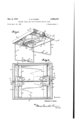
- Figure l is a perspective View of a table embodying the present invention looking up from underside;
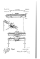
- Figure 2 is a bottom plan View showing legs nested on top
- Figure 3 is a section taken on line 3-3 of Figure 2 with legs dotted in open position;
- Figure 4 is a transverse cross section taken on line l-t of Figure 3;
- Figure 5 is a cross section taken on line 5-5 of Figure 1 under edge of the table where the end of the locking rod is guided;
- Figure 6 is a perspective view of the locking member and rod
- Figure '7 is a fragmentary perspective illustrating the medial locking loop on the hinged side of the leg frames.
- the table comprises a rectangular top a having a depending peripheral flange 2 within which the leg frames are adapted to nest when the table is not in use.
- leg frames of which the opposed sides 4-4 function as legs; one side 5 connects the bottoms of the legs when the table is opened, and the opposed side 'i is hingedly secured to the under face of the table top as by hinges 3-8.
- the two leg frames which as entireties are identified as 3 are hinged to the under face of the table top so that these leg frames are substantially parallel when opened and each leg frame is slightly spaced from the adjacent side of the peripheral flange 2 in a manner to cooperate with said flange in a manner hereinafter more particularly explained.
- each leg frame and the opposite side 5 are provided with medial aligned loops adapted to cooperate with a locking rod i i of sufficient length to extend across the table on its underside with its ends freely slidable in guideways it formed transversely of the peripheral flange 2, as illustrated in Figures 1 and 3.
- Adjacent each end of the locking IOd i4 is fixedly secured a relatively heavy locking bar iii herein illustrated as of rectangular shape and adapted to cooperate with the loops formed in the leg frames to lock .said leg frames in either open or closed position, as will hereinafter appear.
- each leg frame is provided with a medial loop well illustrated in Figures 1 and 5, which comprises spaced arms iii-l0 extending perpendicular to the ad- .iacent aligned portions of the side ?--l, and which legs Ill-l0 are continued perpendicularly through portions H ll which are again extended through portions 12-42, which portions
- the portions l2-l2 are further extended into a medial loop E3 of a size and shape conforming to the size and shape of the locking rod it so as to receive said looking rod and permit said locking rod to gravitate into said loop, as illustrated in Figure 7. From that figure it will also be observed that when the locking rod [4 has gravitated into the position illustrated in that figure, the locking bar E5 fits snugly within the rectangular portion of the loop formed by the opposed arms
- the side of the leg frame 5 opposed to the hinged side thus described, is formed with a single medial loop 6 which when the table is in open position extends outwardly with respect to the leg frame, but which when the leg frames are folded into nested position, extends over and frictionally engages the end portions of the locking rod [4 intermediate each of the locking bars l and the adjacent side 2 of the peripheral flange of the table, thus frictionally securing the leg frames in their folded position.
- the loop 6 is offset on one leg frame as by bends I! to give added depth to that loop 6.
- each leg frame In operation with the table folded as illustrated in Figure 2, to open, the opposed sides 5 of each leg frame are engaged by the fingers of a hand and opened sufficiently to disengage the medial loop 6 from its frictional engagement with the end of the locking rod M.
- the table then being inverted, the leg frames will rock of their own accord to open vertical position, and as they do so the locking rod M with its associated locking bars will drop by gravity into the medial loops l3 formed in the hinged sides 'I'! of the leg frames, as shown in Figures 1 and 5, in which position the table legs are locked in their open position.
- the locking rod I4 may be lifted by hand to disengage the locking bars [5 and thus permit the folding of the leg frames to their folded position, or alternatively, the table can be inverted whereupon the locking rod I4 and its associated locking bars [5 will gravitate to the unlocked position, thus permitting the leg frames to be folded down into locked position, such as illustrated in Figure 2.
- Folding table comprising a top having a depending peripheral flange, two pairs of legs, each pair of legs connected at their upper ends by aligned hinge parts, and a medial locking loop, said locking loop formed with spaced arms parallel with the legs, parts perpendicular to the arms extending therefrom, aligned parts extending perpendicular to said last mentioned parts and parallel with the hinge parts and a medial loop connecting the inner ends of said last mentioned aligned part disposed perpendicular thereto and parallel with the spaced arms, complementary hinge members for securing the hinge parts to the under face of the table, oppositely disposed guide slots formed in the flange of the top in alignment with the medial loops in the locking loops, and a locking rod having its ends slidable in the said guide slots, said locking rod formed with transverse locking bars conforming in size and shape with the locking loops and adapted to gravitate into said locking loops when the legs are in open position, with the medial loops thereof disposed intermediate the table flange and locking loop and with the locking rod
- Folding table comprising a top having a peripheral flange, said flange formed with oppositely disposed guideways perpendicular to the face of the top, a locking rod formed with transversely disposed locking bars adjacent each end and arranged to slide freely with its ends disposed in said guideways, legs arranged in pairs, the legs of each pair connected at their upper ends with aligned hinge parts, and a locking loop, said looking loop including an offset medial loop formed and proportioned to receive portions of the locking rod, when the legs are in their open position,
Landscapes
- Tables And Desks Characterized By Structural Shape (AREA)
Description
Dec. 6 1949 P. M. PADON 2,490,318
FOLDING TABLE LEGS WITH ACTUATOR GRAVITY LOCK Filed April 18, 1947 I 2 Shets-Sheet l Dec. 6, W49 P. M. PADON 2,499,313
FOLDING TABLE LEGS WITH ACTUATOR GRAVITY LOCK Filed April 18, 1947 2 Sheets-Sheet 2 wimwe PRESTON M. PADON Patented Dec. 6, 1949 UNITED STATES TENT OFFICE FOLDING TABLE LEGS WITH ACTUATOR GRAVITY LOCK 2 Claims.
This invention relates to folding tables, and more particularly to folding tables of the type known as card or bridge tables.
An object of the invention is to provide an improved folding table of the type indicated having hinged leg members with a locking mechanism of an improved and simplified structure adapted to operate by gravitation and without the use of springs.
A further object of the invention is to provide an improved and simplified card table of the type indicated conforming in design with the modern metal type of furniture and embodying an improved locking mechanism operable either by gravity or manually as desired, Without the use of springs or spring-controlled catches.
Further objects will more particularly appear in the course of the following description.
The invention consists in the novel construction, arrangement and combinations of parts hereinafter more particularly described and claimed.
Two sheets of drawings accompany is specification as part thereof in which like reference characters indicate like parts throughout.
In the drawings:
Figure l is a perspective View of a table embodying the present invention looking up from underside;
Figure 2 is a bottom plan View showing legs nested on top;
Figure 3 is a section taken on line 3-3 of Figure 2 with legs dotted in open position;
Figure 4 is a transverse cross section taken on line l-t of Figure 3;
Figure 5 is a cross section taken on line 5-5 of Figure 1 under edge of the table where the end of the locking rod is guided;
Figure 6 is a perspective view of the locking member and rod, and
Figure '7 is a fragmentary perspective illustrating the medial locking loop on the hinged side of the leg frames.
In the embodiment of the invention illustrate in the drawings, the table comprises a rectangular top a having a depending peripheral flange 2 within which the leg frames are adapted to nest when the table is not in use.
To the table top are hingedly secured two substantially rectangular leg frames of which the opposed sides 4-4 function as legs; one side 5 connects the bottoms of the legs when the table is opened, and the opposed side 'i is hingedly secured to the under face of the table top as by hinges 3-8. The two leg frames which as entireties are identified as 3, are hinged to the under face of the table top so that these leg frames are substantially parallel when opened and each leg frame is slightly spaced from the adjacent side of the peripheral flange 2 in a manner to cooperate with said flange in a manner hereinafter more particularly explained.
The hinged side of each leg frame and the opposite side 5 are provided with medial aligned loops adapted to cooperate with a locking rod i i of sufficient length to extend across the table on its underside with its ends freely slidable in guideways it formed transversely of the peripheral flange 2, as illustrated in Figures 1 and 3. Adjacent each end of the locking IOd i4 is fixedly secured a relatively heavy locking bar iii herein illustrated as of rectangular shape and adapted to cooperate with the loops formed in the leg frames to lock .said leg frames in either open or closed position, as will hereinafter appear.
For the purpose of securing the leg frames in the open position the hinged side I of each leg frame is provided with a medial loop well illustrated in Figures 1 and 5, which comprises spaced arms iii-l0 extending perpendicular to the ad- .iacent aligned portions of the side ?--l, and which legs Ill-l0 are continued perpendicularly through portions H ll which are again extended through portions 12-42, which portions |2--'i 2 are in alignment and substantially parallel with the portions of the sides 1-4 but spaced in two directions therefrom. The portions l2-l2 are further extended into a medial loop E3 of a size and shape conforming to the size and shape of the locking rod it so as to receive said looking rod and permit said locking rod to gravitate into said loop, as illustrated in Figure 7. From that figure it will also be observed that when the locking rod [4 has gravitated into the position illustrated in that figure, the locking bar E5 fits snugly within the rectangular portion of the loop formed by the opposed arms |l--H and l2!2, the portions of the loop [2-42 and loop it being disposed when this position between the locking bar is and the adjacent side of the peripheral flange 2 which is removed from Figure '2. When the leg frame is in folded position, as illustrated in Figure 2, it will be observed. that the portions iii-NJ of the loop lie against the under face of the table top while portions 1 i--H stand perpendicular with respect to the table top and the portions i'2l2 and medial loop is overlie the lockin rod Hi.
The side of the leg frame 5 opposed to the hinged side thus described, is formed with a single medial loop 6 which when the table is in open position extends outwardly with respect to the leg frame, but which when the leg frames are folded into nested position, extends over and frictionally engages the end portions of the locking rod [4 intermediate each of the locking bars l and the adjacent side 2 of the peripheral flange of the table, thus frictionally securing the leg frames in their folded position. As one leg will overlie the other when in folded position, the loop 6 is offset on one leg frame as by bends I! to give added depth to that loop 6.
In operation with the table folded as illustrated in Figure 2, to open, the opposed sides 5 of each leg frame are engaged by the fingers of a hand and opened sufficiently to disengage the medial loop 6 from its frictional engagement with the end of the locking rod M. The table then being inverted, the leg frames will rock of their own accord to open vertical position, and as they do so the locking rod M with its associated locking bars will drop by gravity into the medial loops l3 formed in the hinged sides 'I'! of the leg frames, as shown in Figures 1 and 5, in which position the table legs are locked in their open position.
To close the table the locking rod I4 may be lifted by hand to disengage the locking bars [5 and thus permit the folding of the leg frames to their folded position, or alternatively, the table can be inverted whereupon the locking rod I4 and its associated locking bars [5 will gravitate to the unlocked position, thus permitting the leg frames to be folded down into locked position, such as illustrated in Figure 2.
The precise size, shape and formation of the various parts may be modified to conform with the desired design for ornamental purposes within the scope of the present invention as pointed out in the appended claims.
Having thus fully described my invention, I claim:
1. Folding table comprising a top having a depending peripheral flange, two pairs of legs, each pair of legs connected at their upper ends by aligned hinge parts, and a medial locking loop, said locking loop formed with spaced arms parallel with the legs, parts perpendicular to the arms extending therefrom, aligned parts extending perpendicular to said last mentioned parts and parallel with the hinge parts and a medial loop connecting the inner ends of said last mentioned aligned part disposed perpendicular thereto and parallel with the spaced arms, complementary hinge members for securing the hinge parts to the under face of the table, oppositely disposed guide slots formed in the flange of the top in alignment with the medial loops in the locking loops, and a locking rod having its ends slidable in the said guide slots, said locking rod formed with transverse locking bars conforming in size and shape with the locking loops and adapted to gravitate into said locking loops when the legs are in open position, with the medial loops thereof disposed intermediate the table flange and locking loop and with the locking rod supported by said medial loops.
2. Folding table comprising a top having a peripheral flange, said flange formed with oppositely disposed guideways perpendicular to the face of the top, a locking rod formed with transversely disposed locking bars adjacent each end and arranged to slide freely with its ends disposed in said guideways, legs arranged in pairs, the legs of each pair connected at their upper ends with aligned hinge parts, and a locking loop, said looking loop including an offset medial loop formed and proportioned to receive portions of the locking rod, when the legs are in their open position,
intermediate the locking bars and the table flange, adjacent the lower ends of the guideways and to raise and support said rod adjacent the under face of the table when the legs are in their folded position and complementary hinge parts securing the hinge parts of the legs against the underface of the top and perpendicular to the locking rod. PRESTON M. PADON.
REFERENCES CITED The following references are of record in the file of this patent:
UNITED STATES PATENTS Number Name Date 965,338 Smiljanic July 26, 1910 1,709,928 Whitney Apr. 23, 1929 FOREIGN PATENTS Number Country Date 319,262 France Nov. 8, 1902
Priority Applications (1)
| Application Number | Priority Date | Filing Date | Title |
|---|---|---|---|
| US742347A US2490318A (en) | 1947-04-18 | 1947-04-18 | Folding table legs with actuator gravity lock |
Applications Claiming Priority (1)
| Application Number | Priority Date | Filing Date | Title |
|---|---|---|---|
| US742347A US2490318A (en) | 1947-04-18 | 1947-04-18 | Folding table legs with actuator gravity lock |
Publications (1)
| Publication Number | Publication Date |
|---|---|
| US2490318A true US2490318A (en) | 1949-12-06 |
Family
ID=24984467
Family Applications (1)
| Application Number | Title | Priority Date | Filing Date |
|---|---|---|---|
| US742347A Expired - Lifetime US2490318A (en) | 1947-04-18 | 1947-04-18 | Folding table legs with actuator gravity lock |
Country Status (1)
| Country | Link |
|---|---|
| US (1) | US2490318A (en) |
Cited By (12)
| Publication number | Priority date | Publication date | Assignee | Title |
|---|---|---|---|---|
| US2572474A (en) * | 1948-07-23 | 1951-10-23 | Bertis F Hamilton | Collapsible table with lock means for paired legs |
| US2682216A (en) * | 1950-03-16 | 1954-06-29 | James J Shields | Endless conveyer press for flattening bags |
| US2723173A (en) * | 1954-01-15 | 1955-11-08 | Gerald S Carrick | Retractable supports and actuating means therefor |
| US2829019A (en) * | 1956-12-31 | 1958-04-01 | American Seating Co | Folding paired leg table with lock |
| US3259080A (en) * | 1965-01-19 | 1966-07-05 | Laroche Andre | Collapsible spring stand |
| US4557200A (en) * | 1983-08-15 | 1985-12-10 | New Products I, Ltd. | Tray with folding legs |
| US6253688B1 (en) * | 2000-03-10 | 2001-07-03 | Frank Lor | Portable table |
| US6561107B1 (en) * | 2000-05-19 | 2003-05-13 | Lockermate Corporation | Foldable shelf assembly |
| US6712009B2 (en) * | 2000-10-09 | 2004-03-30 | Sedus Stoll Ag | Table with folding legs |
| US20060288917A1 (en) * | 2005-06-22 | 2006-12-28 | Wood George W | Tall portable locker table with embedded peg hanger |
| US8490554B2 (en) | 2011-06-30 | 2013-07-23 | Ki Ho Jin | Foldable table |
| USD1063455S1 (en) * | 2023-02-17 | 2025-02-25 | Arteriors Home | Desk |
Citations (3)
| Publication number | Priority date | Publication date | Assignee | Title |
|---|---|---|---|---|
| FR319262A (en) * | 1902-03-04 | 1902-11-08 | Sello | Folding table |
| US965338A (en) * | 1909-08-14 | 1910-07-26 | Mark Smiljanic | Collapsible table or seat. |
| US1709928A (en) * | 1926-08-03 | 1929-04-23 | Samuel Zimmer | Service tray |
-
1947
- 1947-04-18 US US742347A patent/US2490318A/en not_active Expired - Lifetime
Patent Citations (3)
| Publication number | Priority date | Publication date | Assignee | Title |
|---|---|---|---|---|
| FR319262A (en) * | 1902-03-04 | 1902-11-08 | Sello | Folding table |
| US965338A (en) * | 1909-08-14 | 1910-07-26 | Mark Smiljanic | Collapsible table or seat. |
| US1709928A (en) * | 1926-08-03 | 1929-04-23 | Samuel Zimmer | Service tray |
Cited By (12)
| Publication number | Priority date | Publication date | Assignee | Title |
|---|---|---|---|---|
| US2572474A (en) * | 1948-07-23 | 1951-10-23 | Bertis F Hamilton | Collapsible table with lock means for paired legs |
| US2682216A (en) * | 1950-03-16 | 1954-06-29 | James J Shields | Endless conveyer press for flattening bags |
| US2723173A (en) * | 1954-01-15 | 1955-11-08 | Gerald S Carrick | Retractable supports and actuating means therefor |
| US2829019A (en) * | 1956-12-31 | 1958-04-01 | American Seating Co | Folding paired leg table with lock |
| US3259080A (en) * | 1965-01-19 | 1966-07-05 | Laroche Andre | Collapsible spring stand |
| US4557200A (en) * | 1983-08-15 | 1985-12-10 | New Products I, Ltd. | Tray with folding legs |
| US6253688B1 (en) * | 2000-03-10 | 2001-07-03 | Frank Lor | Portable table |
| US6561107B1 (en) * | 2000-05-19 | 2003-05-13 | Lockermate Corporation | Foldable shelf assembly |
| US6712009B2 (en) * | 2000-10-09 | 2004-03-30 | Sedus Stoll Ag | Table with folding legs |
| US20060288917A1 (en) * | 2005-06-22 | 2006-12-28 | Wood George W | Tall portable locker table with embedded peg hanger |
| US8490554B2 (en) | 2011-06-30 | 2013-07-23 | Ki Ho Jin | Foldable table |
| USD1063455S1 (en) * | 2023-02-17 | 2025-02-25 | Arteriors Home | Desk |
Similar Documents
| Publication | Publication Date | Title |
|---|---|---|
| US2938632A (en) | Vertically adjustable folding table | |
| US2942921A (en) | Extension leaf for folding table | |
| US2358883A (en) | Picnic outfit | |
| US1883504A (en) | Combined closet and table | |
| US3201186A (en) | Automobile luggage carrier and table | |
| US2288737A (en) | Folding table | |
| US2353331A (en) | Cabinet structure | |
| US3352390A (en) | Attache case with suspension folder device | |
| US2282393A (en) | Curtain stretcher | |
| US1491039A (en) | Locker seat | |
| US2228248A (en) | Collapsible basket | |
| US2659649A (en) | School desk | |
| US1875772A (en) | Convertible serving table and tray | |
| US2738521A (en) | Folding bedstead for children, especially infants | |
| US2565187A (en) | Vertically collapsible table | |
| US1880909A (en) | Hammock stand | |
| US2100789A (en) | Portable play pen for children | |
| US2734788A (en) | Extension table having hinged apron | |
| US2002607A (en) | Folding crib | |
| US1989778A (en) | Wardrobe case | |
| US1642687A (en) | Combination table and food cabinet | |
| US1409770A (en) | Combination bed and wardrobe | |
| US2946459A (en) | Collapsible shelf structure | |
| US1572282A (en) | Foldable table | |
| US2135836A (en) | Extensible table |