US2530438A - Slide fastener lock - Google Patents
Slide fastener lock Download PDFInfo
- Publication number
- US2530438A US2530438A US79362947A US2530438A US 2530438 A US2530438 A US 2530438A US 79362947 A US79362947 A US 79362947A US 2530438 A US2530438 A US 2530438A
- Authority
- US
- United States
- Prior art keywords
- slider
- tab
- locking member
- cover
- locking
- Prior art date
- Legal status (The legal status is an assumption and is not a legal conclusion. Google has not performed a legal analysis and makes no representation as to the accuracy of the status listed.)
- Expired - Lifetime
Links
- 210000001331 nose Anatomy 0.000 description 22
- 238000006073 displacement reaction Methods 0.000 description 11
- 230000004048 modification Effects 0.000 description 11
- 238000012986 modification Methods 0.000 description 11
- 230000002093 peripheral effect Effects 0.000 description 4
- 230000007246 mechanism Effects 0.000 description 3
- 230000009471 action Effects 0.000 description 2
- 230000008901 benefit Effects 0.000 description 2
- 230000007480 spreading Effects 0.000 description 2
- 239000004753 textile Substances 0.000 description 2
- 241001482320 Trachemys Species 0.000 description 1
- 241001459925 Trachemys stejnegeri Species 0.000 description 1
- 230000000903 blocking effect Effects 0.000 description 1
- 238000010276 construction Methods 0.000 description 1
- 230000000994 depressogenic effect Effects 0.000 description 1
- 238000003780 insertion Methods 0.000 description 1
- 230000037431 insertion Effects 0.000 description 1
- 238000004519 manufacturing process Methods 0.000 description 1
Images



Classifications
-
- A—HUMAN NECESSITIES
- A44—HABERDASHERY; JEWELLERY
- A44B—BUTTONS, PINS, BUCKLES, SLIDE FASTENERS, OR THE LIKE
- A44B19/00—Slide fasteners
- A44B19/24—Details
- A44B19/26—Sliders
- A44B19/30—Sliders with means for locking in position
-
- Y—GENERAL TAGGING OF NEW TECHNOLOGICAL DEVELOPMENTS; GENERAL TAGGING OF CROSS-SECTIONAL TECHNOLOGIES SPANNING OVER SEVERAL SECTIONS OF THE IPC; TECHNICAL SUBJECTS COVERED BY FORMER USPC CROSS-REFERENCE ART COLLECTIONS [XRACs] AND DIGESTS
- Y10—TECHNICAL SUBJECTS COVERED BY FORMER USPC
- Y10T—TECHNICAL SUBJECTS COVERED BY FORMER US CLASSIFICATION
- Y10T24/00—Buckles, buttons, clasps, etc.
- Y10T24/25—Zipper or required component thereof
- Y10T24/2561—Slider having specific configuration, construction, adaptation, or material
- Y10T24/2566—Slider having specific configuration, construction, adaptation, or material including position locking-means attached thereto
- Y10T24/257—Slider having specific configuration, construction, adaptation, or material including position locking-means attached thereto having surface engaging element shifted by reorientation of pull tab
-
- Y—GENERAL TAGGING OF NEW TECHNOLOGICAL DEVELOPMENTS; GENERAL TAGGING OF CROSS-SECTIONAL TECHNOLOGIES SPANNING OVER SEVERAL SECTIONS OF THE IPC; TECHNICAL SUBJECTS COVERED BY FORMER USPC CROSS-REFERENCE ART COLLECTIONS [XRACs] AND DIGESTS
- Y10—TECHNICAL SUBJECTS COVERED BY FORMER USPC
- Y10T—TECHNICAL SUBJECTS COVERED BY FORMER US CLASSIFICATION
- Y10T70/00—Locks
- Y10T70/50—Special application
- Y10T70/5009—For portable articles
- Y10T70/5031—Receptacle
- Y10T70/5035—Bag
- Y10T70/5049—Attache or briefcase, portfolio
- Y10T70/5053—Interengageable slide fastener type
Definitions
- This invention relates to slide fasteners, particularly to slide fasteners of the type in which the slider locks itself against displacement, either in both directions or in the opening direction of the slider travel, until released by actuation of the slider tab.
- Slide fasteners with self-locking sliders of the general type, above referred to usually employ a member having a tooth or a nose forming part of the slider mechanism and normally engaging the scoops of the slide fastener.
- the slider can be unlocked by exerting a pull on the slider tab which causes the toothed member to be lifted out of engagement with the scoops, thereby permitting a displacement of the slider in either direction.
- One of the objects of the invention is to provide a detachable slider tab which is removed when it is desired to lock the slider and which prevents or at least makes it difficult to move the slider without use of the tab.
- Another object of the invention is to provide a removable slider tab and to design the slider proper in such manner that it will receive only a tab specifically designed for the slider in question.
- Another object of the invention is to provide a slider and a removable tab, both so designed that they will co-operate in the manner of a key and a look. In other words, the slider can be locked only when the correct key-like tab is used.
- Another object of the invention is to provide a slider in which the component parts required to be operated by the tab for unlocking the slider are so positioned and constructed that it is extremely difficult to reach and actuate these parts without using the correct key.
- Another object of the invention is to provide means by which a removable tab applied to a slider is biased into a position in which it is secured to the slider, thereby avoiding the danger of a loss of the tab or key.
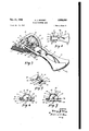
- Fig. 1 is a perspective view of a slider with removable tap according to the invention.
- Fig. 2 is a plan view of the tab proper.
- Fig. 3 is a perspective view, partly in section, of a modification of a slider with removable tab according to the invention.
- Fig. 4 is a plan view of the tab for the slider shown in Fig. 3.
- Fig. 5 is a perspective view of the locking member of the slider according to Fig. 3.
- Fig. 6 is a fractional side view of the locking member and of the tab showing the co-action of the tab with the locking member in one position of the tab.
- Fig. 7 is a fractional side view similar to Fig. 6 showing the tab and the locking member in a different relative position.
- Fig. 8 is a perspective view of a locking member according to the invention as may be used in connection with the slider according to Fig. 1.
- Fig. 9 is a fractional side view of the locking member of Fig. 8 showing the co-action between the locking member and a removable tab in one position of the tab.
- Fig. 10 is a fractional side view similar to Fig. 9 showing the locking member and the tab in a different relative position.
- Fig. 11 is a perspective view, partly in section, of another modification of a slider with removable tab according to the invention.
- Fig. 12 is a fractional view showing the coaction of the tab with the locking member of the slider of Fig. 11.
- Fig. 13 is a perspective view, partly in section, of still another modification of a slider with removable tab according to the invention.
- Fig. 14 is a perspective view of a removable tab to be used in connection with a slider according to Fig. 13.
- Fig. 1 comprises a perspective view of a slide fastener showing a slider generally designated by Ill, and two textile stringers or strips H and I2 to which are fastened conventional scoops l3 and M respectively.
- Slider Ill comprises a top portion l5 and a similarly shaped base portion (not shown) joined to the top portion by a rib (not shown) in a conventional manner. The strips and the scoops fastened thereto are guided between the top and base portion of the slider. When the slider is displaced relative to the strips, the scoops are forced into engagement or disengaged from each other depending upon the direction of the slider movement.
- the locking mechanism of the slider comprises a locking member [8 pivoted to top portion-l5 by a pivot H.
- the free end portion of locking member 18 is provided with a nose l8 (similar to the nose of the locking member shown in Fig. 8 which will be more fully explained hereinafter).
- Nose 18 extends through a corresponding opening IS in top portion l5 of the slider and, by the weight of locking member l8, tends to engage the scoops, thereby preventing displacement of the slider in one direction while allowing displacement in the opposite direction, usually the direction for closing the slide fastener.
- the locking member as shown, is shaped to form a hollow substantially rectangular casing which is received by a correspondingly shaped rectangular body 28 fastened to or integral with top portion i5 and supporting pivot II.
- the slider as hitherto described, is substantially conventional in design and function.
- slider tab is removably rather than permanently fastened to slider i8 as is conventional.
- the slider tab is designed somewhat similar to scissors and comprises two blades or shanks 28a and 21, joined by a pivot 8. Each shank comprises a handle portion 28a and 21a respectively and an operating portion 28b and 21b respectively. Operating portions 28b and 2") are shaped to fit over the free end of locking member i8 and to engage with their respective noses 28 and 29, the corresponding recesses 2 I.
- a loaded leaf spring 38 extending from handle 21 serves to bias noses 28 and 29 into engagement.
- slider tab 25 is removed from locking member l8, then the slider is locked for movement in the opening direction by nose l8 engaging scoops l3 and [4. If it is now desired to unlock the slider, the tab is applied to the slider by pivoting handles 28a and 21a against the action of spring 38 and slipping the then disengaged noses 28 and 29 into recesses 2!.
- the slider can now be unlocked in the same manner as a conventional slider by simply pulling locking member l8 slightly upward by means of tab 25, thereby withdrawing locking nose l8 from the engaged scoops l3 and I4. After placing the slider in the desired position, the tab is again removed thereby preventing or at least making difllcult a tampering with the slider.
- the slider arrangement shown in Figs. 3 to 7 inclusive is based upon the same principle of invention but distinguished from the modification according to Figs. 1. and 2 in that the slider can be unlocked only by means of a key-like tab.
- slider according to Figs. 3 to 7 inclusive comprises a base portion 35 and a top portion 38 joined to the base portion by a rib (not shown).
- the textile strips supporting the scoops to be joined are guided between base portion 35 and top portion 38 in a conventional manner, strip 12 with scoops i4 being shown.
- Slider top 38 is provided with a substantially rectangular opening 31 in which is inserted a locking member generally designated by 38.
- this lock member comprises a center wall 39 of substantially semi-circular shape.
- Center wall 39 is further provided with a cross bar or arm 4
- the collar 48 is positioned above top 38 of the slider while cross bar 4
- the gap 43 is left between cross bar 4i and the adjacent end of collar 48.
- a substantially semi-circular housing or cover 58 fastened to or integral with slider top 36.
- Cover 58 encompasses locking member 38 and is provided at each side with a recess or opening 5! substantially in alignment with gap or recess 43 of the locking member 38.
- One or both side walls of cover 58 are further provided with one or more ribs 52 and grooves 53. These grooves are shown as substantially semi-circular but in certain instances they may also have other shapes. They may be uniformly or non-uniformly spaced and may be of equal or unequal width. Also, the grooves and ribs may be difierent on both sides of the cover.
- the tab 25a coacting with the slider of Fig. 3 is similar to the tab shown in Fig. 2 as to its general design.
- the operating portions 28b and 21b of the blades or shanks 28 and 21 respectively are provided with grooves 55, 58 respectively and ribs 51, 58 respectively corresponding to grooves 53 and ribs 52 of cover 58.
- the forward ends 59 and 88 of shanks 28 and 21 respectively are bent on to form hooks GI, 82 respectively which are urged into engagement by spring 38 as can best be seen in Fig. 4.
- the tab can be pivoted through an angle of about 180 thereby providing for a convenient displacement of the slider in either direction. After the slider is placed in a selected position, the tab is removed by again spreading shank portions 26 and 2! thus relocking the slider.
- the only tab which can be applied to the slider is a tab having ribs or grooves corresponding to the ribs and grooves of the slider.
- the tab must have hooks BI and 62 shaped to engage the locking member and to cause a pivotal movement thereof.
- the slider functions in the nature of a lock which can be opened only with the corresponding key. It will further be noted that it is quite diflicult, if not impossible, to insert tools such as jimmles into cover holes 5
- Figs. 8, 9 and 10 show a locking member suitable for use in connection with a slider arrangement as shown in Fig. 1.
- the locking member comprises an inner section 'Hl fastened to or integral with slider top l5 and an outer section H which is fitted over the inner section somewhat similar to a cover.
- Section N is pivoted to section ill by a pivot 12.
- Portion 13 of the side walls of section ll is slanted to permit a pivotal movement of section 7
- a pin 14 on section ll engaging a corresponding elongated slot 15 in section it serves to guide and limit the pivotal movement of section ii.
- the latter section is provided with a locking nose 16 extending through opening 09 of slider top I5 and locking the slider when the nose engages adjacent scoops.
- a loaded leaf spring Ti between section 10 and ii fastened by a screw or rivet 18 to section 70 serves to bias section ii into a position in which nose it looks the slider.
- the locking member as shown in Figs. 3 to 10 may be operated with a key or tab such as shown in Fig. 4.
- substantially semi-circular recesses 80 are provided in each side wall of section 1 l.
- the locking member according to Figs. 8 to 10 is suitable in connection with the slider of Fig. 1 but it is also quite practical to use the locking member in connection with the slider design of Fig. 3.
- Figs. 11 and 12 show another modification of a slider with removable tab according to the invention.
- the principal difierence between the previously described embodiments and the embodiment according to Figs. 11 and 12 resides in that according to Fig. 11 the locking member of the slider is released by a pulling or lifting movement rather than by a pivotal movement.
- the slider again comprises a base portion 35 and a top portion 36 Joined by a rib.
- the locking member 86 is similar to the locking member 36, the only difference being that collar 40 is extended to ioincross-bar 4
- the pivotal mounting of locking member 66 is the same as has been shown in Figs. 5, 6 and 7 for locking member 38.
- the locking member is covered by a substantially semi-circular housing or cover 86 which is provided on one or both sides with grooves 81 and ribs 88 extending through an angle of about 180. These grooves may be uniformly or nonuniformly spaced and may be of equal or unequal widths. Furthermore, the shape and spacing of the grooves and ribs may be different on both sides of cover 86. Opposite locking member 66,
- openings 89 and 90 are provided in cover 86.
- the tab 25b used in connection with the slider of Fig. 11 is similar in principle to the tabs shown in Figs. 2 and 4.
- the shank portions 26! and 21b are provided with ribs 9
- locking member 66 looks the slider in a manner similar to the one described in connection with Figs. 5, 6 and 7.
- tab 26b is slipped over cover 86 in any angular position relative to slider top 36 and noses 26, 29 are extended through the respective cover holes 89, 90.
- the tab can now be pivoted through an angle of about while exerting a slight pull on tab 25b.
- the locking nose (such as nose d2 of the locking member) is lifted out of its engagement with the adjacent scoop so that the slider is released for displacement in either direction.
- the tab is again removed thereby relocking the slider.
- a locking member 38 is provided as described in detail in connection with Figs. 3, 5, 6 and 7.
- the pivotal movement of looking member 38 is limited by an abutment 96 fastened to or integral with slider top 36.
- a similar abutment may of course also be provided in the modification according to Fig. 3.
- the principal difference between the modification of Fig. 13 and the previously described modifications resides in the design of the tab and the parts of the slider proper coacting with the tab.
- a substantialhr semicircular housing or cover 96 extends from slider top 36.
- the cover is provided with an elongated peripheral slot 91 which at one end ends in a transverse slot 96 positioned substantially in alignment with gap '33 of locking member 38.
- Ribs 99 and intermediate grooves H00 corresponding in function to the ribs 52 and grooves 53 of Fig. 3 are provided on the inside walls of cover 96.
- the tab intended for use in connection with the slider according to Fig. 13 is shown in Fig. 14. According to this latter figure, the tab, generally designated by i0! is shaped somewhat similar to a conventional fiat key. The total width of the key is selected
- the slots or recesses of tab Ill must of course match the ribs and grooves of the cover.
- the tab is further provided with a T-shaped slot Ill, the longitudinal branch of which is designed to fit and engage center wall 8! of locking member 33 while the transverse branch of slot I fits and engages collar ll of locking member 30.
- a T-shaped slot Ill the longitudinal branch of which is designed to fit and engage center wall 8! of locking member 33 while the transverse branch of slot I fits and engages collar ll of locking member 30.
- the slider will relock itself as locking member 38 will return into its locking position by its own weight or by means of a suitable retrieving spring.
- a leaf spring I II is provided fastened to slider top 38 by a rivet III or any other suitable means. This spring is so shaped that it will force an inserted tab slightly beyond transverse slot 98 thereby preventing the tab from falling out of slot 98. When it is desired to remove the tab, spring I I I is slightly depressed by means of the tab.
- the modification according to these figures substantially duplicates a lock and key. It has the particular advantage that it is very simple in design and manufacture.
- the key-like tab consists of one piece. The smooth outside of the slider prevents any deformation of the grooves and ribs.
- a slider lock for a slide fastener comprising a locking member capable of locking the slider in one position and of being moved into a release position, a cover member provided on said slider and constructed to conceal said locking member, said cover member having a ward portion including grooves and ribs and an opening providing access to the locking member.
- a slider lock for a slide fastener comprising a locking member capable of locking the slider in one position and of being moved into a release position, a cover member provided on said 8 slider and constructed to member.
- said cover member having a plane wall portion having therein concentric substantially semi-circular grooves and ribs and an opening providing access to the locking member, said cover member opening being positioned approximately in the center point for said semi-circula grooves and ribs.
- a slider lock for aslide fastener comprising a locking member capable of locking the slider in one position and of being moved into a release position, a cover member constructed and positioned to conceal said locking member, said cover member having a, semi-cylindrical shape, the plane sides of the cover member being positioned parallel to the direction of displacement of the slider relative to a slide fastener, the base of the semi-cylindrical member being positioned adjacent to the slider portion engaging the slide fastener, the inside of at least one of the plane walls having thereon substantially semi-circular concentric grooves and ribs, the semi-cylindrical wall portion of the cover member including a peripheral slot extending through an arc corresponding substantially to the circumferential length of said grooves and ribs, one end of said peripheral slot being extended into a transverse slot.
- said locking member comprises a pivotal element having a tooth thereon, said pivotal element being arranged to normally assume a. position in which said tooth engages the scoops of'a respective slide fastener, thereby locking the same, and to be pivoted into a, release position in which said tooth is disengaged from the scoops.
- a slider lock for. slide fastener of the type having a pair of flexible stringers and interlocking members comprising a slider body having a guide channel to receive said stringers and interconceal said locking recesses and teeth.
- assaase locking members a movable locking member supported on the slider body and capable of locking the slider to the stringers in one position and of being moved into a release position, and a guard member attached to the slider body facing the locking member and blocking access to the same, said guard member having an opening therethrough positioned in alignment with the looking member and arranged to receive a key member for operating said locking member, said guard member including a shaped portion adapted to be engaged by a corresponding shaped portion of an inserted key member to permit pivotal movement of the key relative to the guard member causing movement of the locking member into its release position.
Landscapes
- Slide Fasteners (AREA)
Priority Applications (4)
| Application Number | Priority Date | Filing Date | Title |
|---|---|---|---|
| US79362947 US2530438A (en) | 1947-12-24 | 1947-12-24 | Slide fastener lock |
| GB3244348A GB655997A (en) | 1947-12-24 | 1948-12-15 | A slider lock for slide fasteners |
| CH310804D CH310804A (fr) | 1947-12-24 | 1948-12-22 | Curseur à blocage automatique pour fermeture à curseur. |
| DEP26310A DE859284C (de) | 1947-12-24 | 1948-12-23 | Schliessschieber fuer Reissverschluesse |
Applications Claiming Priority (1)
| Application Number | Priority Date | Filing Date | Title |
|---|---|---|---|
| US79362947 US2530438A (en) | 1947-12-24 | 1947-12-24 | Slide fastener lock |
Publications (1)
| Publication Number | Publication Date |
|---|---|
| US2530438A true US2530438A (en) | 1950-11-21 |
Family
ID=25160404
Family Applications (1)
| Application Number | Title | Priority Date | Filing Date |
|---|---|---|---|
| US79362947 Expired - Lifetime US2530438A (en) | 1947-12-24 | 1947-12-24 | Slide fastener lock |
Country Status (4)
| Country | Link |
|---|---|
| US (1) | US2530438A (fr) |
| CH (1) | CH310804A (fr) |
| DE (1) | DE859284C (fr) |
| GB (1) | GB655997A (fr) |
Cited By (5)
| Publication number | Priority date | Publication date | Assignee | Title |
|---|---|---|---|---|
| US2785452A (en) * | 1953-09-16 | 1957-03-19 | Elmcroft Corp | Slider locking and release mechanism for slide fasteners |
| US2786250A (en) * | 1953-10-13 | 1957-03-26 | Elmcroft Corp | Combination locking and release slider for slide fasteners |
| US4570309A (en) * | 1982-03-25 | 1986-02-18 | Yoshida Kogyo K.K. | Slide fastener slider with detachable pull tab |
| EP0280071A1 (fr) * | 1987-02-03 | 1988-08-31 | Yoshida Kogyo K.K. | Dispositif de blocage pour curseurs de fermeture à glissière |
| US6588072B1 (en) * | 2001-12-31 | 2003-07-08 | Yu-Pau Lin | Zipper slide |
Citations (8)
| Publication number | Priority date | Publication date | Assignee | Title |
|---|---|---|---|---|
| US507408A (en) * | 1893-10-24 | Samuel c | ||
| US1003331A (en) * | 1911-03-21 | 1911-09-12 | Yancey Q Caldwell | Lock. |
| US1667254A (en) * | 1927-04-09 | 1928-04-24 | Hedrich Herman | Padlock |
| US2071544A (en) * | 1934-12-31 | 1937-02-23 | Kroll Harry David | Self-locking slider for multiple fasteners |
| GB499253A (en) * | 1937-07-21 | 1939-01-20 | Cartier | Improvements in or relating to the operating tabs of sliding fasteners |
| US2166581A (en) * | 1934-07-21 | 1939-07-18 | Talon Inc | Slider lock |
| DE687187C (de) * | 1936-09-16 | 1940-01-24 | Alfred Boenecke | Verschliessbarer Reissverschlussschieber |
| US2318887A (en) * | 1938-04-28 | 1943-05-11 | Yale & Towne Mfg Co | Key for cylinder locks |
-
1947
- 1947-12-24 US US79362947 patent/US2530438A/en not_active Expired - Lifetime
-
1948
- 1948-12-15 GB GB3244348A patent/GB655997A/en not_active Expired
- 1948-12-22 CH CH310804D patent/CH310804A/fr unknown
- 1948-12-23 DE DEP26310A patent/DE859284C/de not_active Expired
Patent Citations (8)
| Publication number | Priority date | Publication date | Assignee | Title |
|---|---|---|---|---|
| US507408A (en) * | 1893-10-24 | Samuel c | ||
| US1003331A (en) * | 1911-03-21 | 1911-09-12 | Yancey Q Caldwell | Lock. |
| US1667254A (en) * | 1927-04-09 | 1928-04-24 | Hedrich Herman | Padlock |
| US2166581A (en) * | 1934-07-21 | 1939-07-18 | Talon Inc | Slider lock |
| US2071544A (en) * | 1934-12-31 | 1937-02-23 | Kroll Harry David | Self-locking slider for multiple fasteners |
| DE687187C (de) * | 1936-09-16 | 1940-01-24 | Alfred Boenecke | Verschliessbarer Reissverschlussschieber |
| GB499253A (en) * | 1937-07-21 | 1939-01-20 | Cartier | Improvements in or relating to the operating tabs of sliding fasteners |
| US2318887A (en) * | 1938-04-28 | 1943-05-11 | Yale & Towne Mfg Co | Key for cylinder locks |
Cited By (5)
| Publication number | Priority date | Publication date | Assignee | Title |
|---|---|---|---|---|
| US2785452A (en) * | 1953-09-16 | 1957-03-19 | Elmcroft Corp | Slider locking and release mechanism for slide fasteners |
| US2786250A (en) * | 1953-10-13 | 1957-03-26 | Elmcroft Corp | Combination locking and release slider for slide fasteners |
| US4570309A (en) * | 1982-03-25 | 1986-02-18 | Yoshida Kogyo K.K. | Slide fastener slider with detachable pull tab |
| EP0280071A1 (fr) * | 1987-02-03 | 1988-08-31 | Yoshida Kogyo K.K. | Dispositif de blocage pour curseurs de fermeture à glissière |
| US6588072B1 (en) * | 2001-12-31 | 2003-07-08 | Yu-Pau Lin | Zipper slide |
Also Published As
| Publication number | Publication date |
|---|---|
| GB655997A (en) | 1951-08-08 |
| DE859284C (de) | 1952-12-11 |
| CH310804A (fr) | 1955-11-15 |
Similar Documents
| Publication | Publication Date | Title |
|---|---|---|
| US4350375A (en) | Double-slider zipper latching device | |
| US4287731A (en) | Handcuffs | |
| US4327566A (en) | Latching device and combination locking means | |
| US3597945A (en) | Latching device and combination locking means | |
| US2461398A (en) | Portable door fastener | |
| US4123828A (en) | Automatically locking dual-tab slider for slide fasteners | |
| JPH0738608Y2 (ja) | スライドフアスナー用ダイヤル錠 | |
| US2495176A (en) | Reversible slider for slide fasteners | |
| US6708373B2 (en) | Gripping device for a cooking utensil | |
| JPS6261756B2 (fr) | ||
| US2741114A (en) | Combination lock slider | |
| US3961505A (en) | Latching device including combination locking means | |
| US2166581A (en) | Slider lock | |
| US2530438A (en) | Slide fastener lock | |
| EP0492403A1 (fr) | Curseur blockable pour fermeture à glissière | |
| US1964936A (en) | Permutation lock | |
| US1401030A (en) | Lock | |
| US2123512A (en) | Separable fastener | |
| US3025692A (en) | Key-locked fastenings for travel bags, boxes and the like | |
| US3978697A (en) | Latching device | |
| US3736778A (en) | Combination lock | |
| US1892964A (en) | Padlock | |
| US1806163A (en) | Toy handcuff | |
| US3405544A (en) | Combination lock | |
| CN108209064B (zh) | 拉链头锁扣装置 |