US254648A - Schai t - Google Patents
Schai t Download PDFInfo
- Publication number
- US254648A US254648A US254648DA US254648A US 254648 A US254648 A US 254648A US 254648D A US254648D A US 254648DA US 254648 A US254648 A US 254648A
- Authority
- US
- United States
- Prior art keywords
- spur
- pulley
- wheel
- pinion
- shaft
- Prior art date
- Legal status (The legal status is an assumption and is not a legal conclusion. Google has not performed a legal analysis and makes no representation as to the accuracy of the status listed.)
- Expired - Lifetime
Links
- 230000009514 concussion Effects 0.000 description 1
- 238000010276 construction Methods 0.000 description 1
- 230000000694 effects Effects 0.000 description 1
- 230000007704 transition Effects 0.000 description 1
Images
Classifications
-
- F—MECHANICAL ENGINEERING; LIGHTING; HEATING; WEAPONS; BLASTING
- F16—ENGINEERING ELEMENTS AND UNITS; GENERAL MEASURES FOR PRODUCING AND MAINTAINING EFFECTIVE FUNCTIONING OF MACHINES OR INSTALLATIONS; THERMAL INSULATION IN GENERAL
- F16H—GEARING
- F16H37/00—Combinations of mechanical gearings, not provided for in groups F16H1/00 - F16H35/00
- F16H37/02—Combinations of mechanical gearings, not provided for in groups F16H1/00 - F16H35/00 comprising essentially only toothed or friction gearings
- F16H37/021—Combinations of mechanical gearings, not provided for in groups F16H1/00 - F16H35/00 comprising essentially only toothed or friction gearings toothed gearing combined with continuously variable friction gearing
Definitions
- This invention is designed to provide for changing the speed of arbors or shafting without the sudden jar hitherto experienced with devices employed for such purpose; and it consists in a novel combination of parts whereby said object is secured.
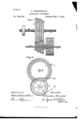
- Figure 1 is a sideview and partial sectional view of an apparatus constructed according to my said invention
- Fig. 2 is an end View taken in a plane at right angles to Fig. 1.
- A is a driving-shaft, provided with a fast pulley, a, and a loose pulley, b also, fast upon the shaft A is a spur-pinion, c, which gears into a spur-wheel, d, on the driven shaft B, the pinion c and spur-wheel cl being so proportioned as to give the minimum speed desired to the shaft B.
- the maxi-mum speed of said shaft is secured through a spur-pinion, e, which gearsinto the spur-wheel f, the said spur-wheel f having of course a smaller diameter than the spur-wheel d, while the spur-pinion c has a proportionally larger diameter.
- the spurpinione is fast upon a sleeve, 9, which is concentric with the shaft A and has fast upon it a pulley, h.
- Between the spur-wheels d and f are two spur-wheels, t and k, which gear respectively into two spur-pinions, m and n, the spur-wheel It being of less diameter than the spur-wheel t, and the spur-pinion n being proportionally of larger diameter than the spurpinion m.
- the spur-pinion is fast to a sleeve, 7', which is loose upon the driving-shaft A, and which is fast upon its opposite extremity.
- the pulley s and the spur-pinion n are fast upon the end of a sleeve, 20, which is loose upon the sleeve 7", and which has fast upon its opposite end a pulley, m.
- the pulleys h w s a b are all of uniform diameter, so that a belt, 0, may be run from one to the other, after the ordinary manner of slipping a belt from a fast pulley to a loosepulley, &c.
- I may term the spu'r-pinions m n as idler-pinions, and in like manner the spur-wheels t k as idler spurwheels, their importance arising not so much from their action in rotating the shaft B as from the fact that they reduce and destroy the concussion which would otherwise arise from shifting the speed of said shaft from one ratio of velocity to another.
- the speed of the shaft B will be quickened instead of slackened, and with the same avoidance of jar as in the reverse operation.
- no motion will be communicated to any of the parts other than said pulley, in-
- What I claim as my invention is The combination of the idler-pinions m n, idler spur-wheels 6 7c, and the pulleys s m and sleeves w 1', with the driving-sh aft A, carrying the pulleys a h, sleeve 9, and pinions e c, and 15 the driven shaft B, carrying the spur-wheels f d, the idler-pinions m n being placed between the pinions e c, and the several parts being constructed, combined, and arranged substantially its described, to effect the purpose herein set 20 'orth.
Landscapes
- Engineering & Computer Science (AREA)
- General Engineering & Computer Science (AREA)
- Mechanical Engineering (AREA)
- Devices For Conveying Motion By Means Of Endless Flexible Members (AREA)
Description
(No Model.)
0. HERRSGHAFT.
' MECHANICAL MOVEMENT.
No. 254,648. Patented. Mar. 7,1882.
F/gr/ UNITED STAT S- PATENT OFFICE.
CHRISTOPHER HERRSQHAFT, on BROOKLYN, NEW YORK.
ME CHANlCAL MOVEMENT SPECIFICATION forming part of Letters Patent No. 254,648, dated March 7, 1882. Application filed January 6, 1882. (No model.)
To all whom t't may concern Be it known that I, CHRISTOPHER HERR- SCHAFT, of Brooklyn, in the county of Kings and State of New York, haveinvented an Improvement in Mechanical Movements, of which the following is a specification.
This invention is designed to provide for changing the speed of arbors or shafting without the sudden jar hitherto experienced with devices employed for such purpose; and it consists in a novel combination of parts whereby said object is secured.
Figure 1 is a sideview and partial sectional view of an apparatus constructed according to my said invention, and Fig. 2 is an end View taken in a plane at right angles to Fig. 1.
A is a driving-shaft, provided with a fast pulley, a, and a loose pulley, b also, fast upon the shaft A is a spur-pinion, c, which gears into a spur-wheel, d, on the driven shaft B, the pinion c and spur-wheel cl being so proportioned as to give the minimum speed desired to the shaft B. The maxi-mum speed of said shaft is secured through a spur-pinion, e, which gearsinto the spur-wheel f, the said spur-wheel f having of course a smaller diameter than the spur-wheel d, while the spur-pinion c has a proportionally larger diameter. The spurpinione is fast upon a sleeve, 9, which is concentric with the shaft A and has fast upon it a pulley, h. Between the spur-wheels d and f are two spur-wheels, t and k, which gear respectively into two spur-pinions, m and n, the spur-wheel It being of less diameter than the spur-wheel t, and the spur-pinion n being proportionally of larger diameter than the spurpinion m. The spur-pinion is fast to a sleeve, 7', which is loose upon the driving-shaft A, and which is fast upon its opposite extremity. The pulley s and the spur-pinion n are fast upon the end of a sleeve, 20, which is loose upon the sleeve 7", and which has fast upon its opposite end a pulley, m. The pulleys h w s a b are all of uniform diameter, so that a belt, 0, may be run from one to the other, after the ordinary manner of slipping a belt from a fast pulley to a loosepulley, &c.
. It will be observed that the pinions c, m, n, and e are each run from one or the other of the pulleys h a."- s a, and that the larger of the said spur-pinions gear with the smaller of the spurwheels, and vice versa, so that the highest speed is obtained when the spur-pinion 12 rotates the spur-wheel f, the next highest speed when the spur-pinion n acts upon the gear-wheel k, the next highest when the spur-pinion m acts upon the spur-wheel t, and the slowest when the spur-pinion 0 acts upon the largest spur-wheel d, so that by these means the transfer of the driving-belt 0 from the pulley a to the pulley h, instead of being done suddenly, as by the ordinary construction and operation, is done gradually, inasmuch as the speed of the shaft B is slackened by two successive stepsnamely, that from the pulley s to the pulleym and from the latter to the pulley h-which interposes the action of the spur-pinion a and spur-wheel k and ofthe spur-pinionm and spurwheel 41 between the action of the spur-pinion 0 upon the spur-wheel f and the action of the spurpinion 0 upon the spur-wheel (1, thereby insuring a transition from one degree of velocity to another without the sudden jar which has accompanied the use of the pulley a and its adjuncts in connection with the pulley h and its adjuncts, as has hitherto been done.
For convenience of description I may term the spu'r-pinions m n as idler-pinions, and in like manner the spur-wheels t k as idler spurwheels, their importance arising not so much from their action in rotating the shaft B as from the fact that they reduce and destroy the concussion which would otherwise arise from shifting the speed of said shaft from one ratio of velocity to another. Of course, when the movement of the driving-belt (J is from the pulley h to the pulley a the speed of the shaft B will be quickened instead of slackened, and with the same avoidance of jar as in the reverse operation. When the belt is run upon the pulley b no motion will be communicated to any of the parts other than said pulley, in-
asmuch as the latter is loose upon the said nected by bands or belts; or, when desired, the 100 connections between the said pinions and the said wheels may be made after the manner of what is commonly known as frictional gearmg.
5 It is also to be observed that additional intermediate pinions and wheels may be added to those interposed, as hereinbefore explained, in proportion as the difference between the fastest and slowest speed of the shaft 13 is de- 10 sired.
What I claim as my invention is The combination of the idler-pinions m n, idler spur-wheels 6 7c, and the pulleys s m and sleeves w 1', with the driving-sh aft A, carrying the pulleys a h, sleeve 9, and pinions e c, and 15 the driven shaft B, carrying the spur-wheels f d, the idler-pinions m n being placed between the pinions e c, and the several parts being constructed, combined, and arranged substantially its described, to effect the purpose herein set 20 'orth.
CHRISTOPHER HERRSOHAFT.
Witnesses:
THOMAS E. CROSSMAN, ROBERT W. MATTHEWS.
Publications (1)
| Publication Number | Publication Date |
|---|---|
| US254648A true US254648A (en) | 1882-03-07 |
Family
ID=2323943
Family Applications (1)
| Application Number | Title | Priority Date | Filing Date |
|---|---|---|---|
| US254648D Expired - Lifetime US254648A (en) | Schai t |
Country Status (1)
| Country | Link |
|---|---|
| US (1) | US254648A (en) |
-
0
- US US254648D patent/US254648A/en not_active Expired - Lifetime
Similar Documents
| Publication | Publication Date | Title |
|---|---|---|
| US254648A (en) | Schai t | |
| US628453A (en) | Chainless cycle. | |
| US606158A (en) | bfjlanger | |
| US812888A (en) | Speed-changing mechanism. | |
| US977449A (en) | Variable-speed mechanism. | |
| US743053A (en) | Reversing mechanism. | |
| US826969A (en) | Variable-speed and reversing mechanism. | |
| US724312A (en) | Variable-speed gear. | |
| US1069004A (en) | Transmission-gearing. | |
| US1081092A (en) | Transmission-gearing. | |
| US770057A (en) | Clutch for variable-speed counter-shafts. | |
| US285213A (en) | Combined differential gear and frjction-clutch | |
| US722245A (en) | Variable-speed-transmission mechanism. | |
| US794227A (en) | Speed-changing gear. | |
| US259572A (en) | Christian e | |
| US1216865A (en) | Mechanism for transmitting power. | |
| US407092A (en) | Power-transmitting device | |
| US749602A (en) | Fkedekic j | |
| US278070A (en) | Edgar | |
| US725223A (en) | Variable-speed gear. | |
| US407091A (en) | Power-transmitting device | |
| US1024818A (en) | Variable-speed gearing. | |
| US1187848A (en) | Variable-speed gearing. | |
| US928894A (en) | Variable-speed gearing. | |
| US730066A (en) | Change and reversing gear. |