US2556549A - Gun mounting - Google Patents
Gun mounting Download PDFInfo
- Publication number
- US2556549A US2556549A US470505A US47050542A US2556549A US 2556549 A US2556549 A US 2556549A US 470505 A US470505 A US 470505A US 47050542 A US47050542 A US 47050542A US 2556549 A US2556549 A US 2556549A
- Authority
- US
- United States
- Prior art keywords
- gun
- arm
- guns
- arms
- supporting
- Prior art date
- Legal status (The legal status is an assumption and is not a legal conclusion. Google has not performed a legal analysis and makes no representation as to the accuracy of the status listed.)
- Expired - Lifetime
Links
- 238000010304 firing Methods 0.000 description 5
- 230000005484 gravity Effects 0.000 description 3
- NIOPZPCMRQGZCE-WEVVVXLNSA-N 2,4-dinitro-6-(octan-2-yl)phenyl (E)-but-2-enoate Chemical compound CCCCCCC(C)C1=CC([N+]([O-])=O)=CC([N+]([O-])=O)=C1OC(=O)\C=C\C NIOPZPCMRQGZCE-WEVVVXLNSA-N 0.000 description 2
- 230000000994 depressogenic effect Effects 0.000 description 2
- 230000003028 elevating effect Effects 0.000 description 2
- 230000000717 retained effect Effects 0.000 description 2
- IIDJRNMFWXDHID-UHFFFAOYSA-N Risedronic acid Chemical compound OP(=O)(O)C(P(O)(O)=O)(O)CC1=CC=CN=C1 IIDJRNMFWXDHID-UHFFFAOYSA-N 0.000 description 1
- 230000000295 complement effect Effects 0.000 description 1
- 238000010276 construction Methods 0.000 description 1
- 230000000452 restraining effect Effects 0.000 description 1
Images


Classifications
-
- F—MECHANICAL ENGINEERING; LIGHTING; HEATING; WEAPONS; BLASTING
- F41—WEAPONS
- F41A—FUNCTIONAL FEATURES OR DETAILS COMMON TO BOTH SMALLARMS AND ORDNANCE, e.g. CANNONS; MOUNTINGS FOR SMALLARMS OR ORDNANCE
- F41A27/00—Gun mountings permitting traversing or elevating movement, e.g. gun carriages
- F41A27/06—Mechanical systems
Definitions
- This invention relates to gun mountings, and refers more particularly to those arrangements, normally intended for use against aircraft, in which the gun (or guns) proper-usually a machine gun or automatic rifle-is (or are) mounted on a supporting part which is pivoted to enable the gun (or guns) to be swung for both traverse and elevation.
- gun mounting is described in my prior Patent No. 2,228,179.
- a gun (or guns) on a mounting of this type should be capable of being employed against ground forces which might, in some cases, as for example when the gun mounting is carried on a lorry, be at a lower level than the gun (or guns) If it were attempted to depress the gun (or guns) on such ground forces by swinging the supporting part sufliciently far down, the axis of the gun (or guns) might be at such a low level both that sighting by the gunner would be inconvenient and that near objects such as a part of the lorry would intervene between the gun (or guns) and the target.
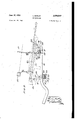
- Figure I is a side elevation of such a gun arm, having associated means according to the invention for mounting thereon a single Bren gun, said gun being shown in its normal position relative to said gun arm in full lines, and in a downwardly tilted position relative to said gun arm in chain dotted lines.
- Figure 2 is a plan of said gun arm and associated means
- Figure 3 is an end elevation of the same looking from the direction of the arrow III of Figure 2.
- Figure 4 is a side" elevation showing a similar gun arm, having associated means according to guns, the guns being in the normal position relative to the gun arm.
- Figure 5 is a plan of the same with certain parts omitted for clearness.
- Figure 6 is a side elevation of the same with the guns in a downwardly tilted position relative to said gun arm.
- the gun arm I is equivalent to the gun arm 14 of said prior Patent No. 2,228,179 and is mounted in the same way so as to be capable of swinging both for elevation and traverse about axes at the rear of the rotatable gunners seat.
- this gun arm is shown broken off at the rear end near these swing axes, and the remainder of the gun mounting which may be identical with that described in said prior specification is not shown.
- the fixtures for supporting the gun fore and aft from this gun arm I comprise respective short supporting arms 2 and 3 each pivotally mounted at one end on said gun arm I so as to turn about horizontal transverse axes X-X and YY, and terminating at the other end in the required standard fitting for attachment to the" particular type of gun being employed (in the present case a Bren gun).
- the rear supporting arm 2 is considerably longer than the fore supporting arm 3 and, in the normal state-that is when the gun is to be used for its normal anti-aircraft purposesthe supporting arms may be arranged as shown with the front supporting arm 3 inclined a little rearwardly of the vertical and the rear supporting arm 2 inclined rearwardly nearly to the horizontal. With this arrangement the gun will be supported in a position more or less parallel to the gun arm which may be the most convenient position for normal use.
- the gun arm I were lowered to the necessary angle the sighting by the gunner would be inconvenient and a part of the lorry might intervene between the gun and its target, but by simply pushing the gun forwardly, the rear supporting arm 2 turns to the vertical position and the front supporting arm is inclined forwardly.
- the gun is now directed downwardly relative to the gun arm I and may be easily depressed on the ground forces by the operation of said gun arm, since the axis of the gun is now much higher than if it were brought to the same angle by movement the front part la.
- the gun may be adjusted to any required angle with respect to the gun arm, and, in particular, it may be adapted very rapidly for use against ground forces.
- the supporting arms 2 and 3 are adapted to be locked against turning by screwing up a hand Wheel fl and a nut 5 respectively, and these are loosened when it is wished to adjust the gun.
- the supporting arms 2 and 3 are of adjustable length each consisting of telescoping parts and means for locking them at an adjusted relative position.
- the arm 2 consists of a tubular portion 2a and a portion 2?) adapted to slide longitudinally within it, the portion 2a being longitudinally slit and a nut 6 being provided to tighten and loosen said portion 2a on the portion 2b.
- the arm 3 consists of a tubular portion 3a, a portion 3b sliding within it and a nut and bolt clamp l for tightening and loosening said portion 3a on said portion 31).
- the pivotal mounting of the supporting arms 2 and 3 on the gun arm I is effected by providing respective bearing pins 8 and 9 projecting transversely and horizontally from said gun arm and pivoting the ends of said supporting arms on said bearing pins.
- the portions 2a and 3a of said supporting arms are provided with split bearing bosses 2c and which surround the bearing pins 5 and 9, and are adapted to be tightened and loosened thereon by means of the hand wheel a and nut 5 respectively.
- the gun arm I is of adjustable length consisting of two telescoping parts la and lb, the rear part lb being the inner part and the front part la the outer part.
- these two telescoping parts instead of being of circular section tubing as in said prior specification, are
- Both the bearing pins 8 and 9 are mounted on The front bearing pin 9 is permanently and rigidly secured to said front part la.
- the rear bearing pin 8 is permanently and rigidly secured to a tubular bush I! which is of the same square section as said part la and is mounted on the rear end thereof.
- Both said tubular bush l9 and the rear end of the front part la, but not the rear part lb, are slotted to enable them to expand and contract, and the tubular bush I0 is provided with a tightening hand wheel ll whereby it may be tightened or loosened on the front part la, thereby tightening or loosening said front part on the rear part lb.
- the fittings mounted on the ends of the supporting arms 2 and 3 for attachment to the gun are, in the example illustrated, those for a Bren type of gun, consisting simply of flattened end portions with eyelet holes in them.
- a Bren gun duly mounted on these fittings is shown in Figure 1 in full lines in the normal position. The position of the gun is indicated in chain dotted lines in the downwardly directed position.
- the reference l2 designates a handle for swinging the gun arm.
- the gun arm I3 is again equivalent to the gun arm 14 of said prior Patent No. 2,228,179 except that, in this case said gun arm is shown as constituted by a single piece and not two telescoping parts.
- the gun mounting is, in this case, for two guns.
- the fixtures for supporting the two guns fore and aft from this gun arm l3 comprise a pair of equal short supporting arms l4 rigidly mounted parallel to each other on a common horizontal transverse shaft l5 which is rotatably mounted on said gun arm l3 near the forward end, and a pair of equal short supporting arms It rigidly mounted parallel to each other on a common horizontal transverse shaft ll which is rotatably mounted on said gun arm 13 further towards the rear.
- These short supporting arms :4 and Hi each terminate at their free ends in the required standard fitting for pivotal attachment to the complementary fitting of the particular type of gun being employed, in the present instance a Bren gun.
- the two supporting arms l4 are adapted to be attached to the forward fittings of the respective guns and the two supporting arms It on to the rear fittings of the respective guns.
- the rear supporting arms l-S are considerably longer than the forward supporting arms l4, and in the normal state--that is when the guns are to be used for their normal anti-aircraft purposes-the two supporting arm units may be arranged as shown in Figure 4 with the forward supporting arms Ill inclined a little rearwardly of the vertical and the rear supporting arms l6 inclined rearwardly nearly to the horizontal. With this arrangement the guns will be supported as indicated in dotted lines in Figure 4, in a position slightly upwardly inclined with respect to the gun arm l3.
- the guns When it is desired to attack ground forces the guns are simply pushed forwardly so that the rear supporting arms l6 turn to a position approaching the vertical and the front supporting arm is inclined forwardly towards the horizontal as indicated in Figure 6.
- the guns are now directed downwardly relative to the gun arm l3 and may be easily depressed on the ground forces, since the axes of the guns are now much higher than if they were brought to the same angle by movement of the gun arm l3.
- ] is provided whereby the rear shaft I! can be clamped in its bearing, but in cases where great speed of action is necessary the guns could be used, at least in the rear position where the recoil would aid gravity, without this wheel 20 being tightened.
- the two guns are provided with common sights viz. a fore sight 2
- a sight bar 23 which is mounted on the gun arm [3 and is adapted to tilt relatively thereto in unison with the guns so that, at eiher position of the guns, the common sights are operative.
- This sight bar 23 is mounted on the gun arm in substantially the same way as each of the two guns.
- ward short supporting arm is mounted on the forward shaft parallel and equal to the arms l4f,.an'd an additional rear short supporting arm is mounted on the rear shaft [1 parallel and equal to the arms Hi.
- these additional short supporting arms are not seen in any figure of In Figures 4' and 6- they are concealed behind the arms I4 and f6, and in Figure 5 they are concealed beneath the sight bar 23.
- these additional short supporting arms are pivotally connected to the lower ends of lugs 24 and 25 rigidly secured to, and extending downwardly from, the sight bar 23.
- the sight bar 23 will be tilted in unison with the "guns as the. latter are moved to and from their two positions and the sights will be operative for both positions.
- Each of the short supporting arms I4 and. I5, and e ach'of the additional short supporting arms for the sight bar (which are substantially identical. with the short supporting arms 14 and !5),
- short supporting arms are only effected during erection of the gun mounting in order to fit said arms properly to the guns and sight bar, and ensure that all the front supporting arms on the one hand, and all the rear supporting arms on the other hand, are of the same length and parallel.
- each short supporting arm comprises two portions which telescope one within the other.
- the portion which is mounted on the shaft takes the form of a tube having a longitudinal slit 26 at its extremity and the other portion takes the form of a rod which is embraced by, and projects from, said tube.
- the rod portion is clamped at the adjusted position relative to the tube portion by drawing together, by means of a bolt 21, two lugs 28 which project from the tube portion on either side of the slit 26.
- Each tube portion is mounted on the respective shaft by means of a transverse tubular slit boss 29 in which said tube portion terminates and which encloses said shaft.
- This boss 29 is clamped onto the shaft by drawing together, by means of a bolt 30, two lugs 3
- the front shaft l 5 bears in abearing 32 rigidly mounted above the gun arm l3 and the rear shaft I1 bears in a similar bearing (not seen) rigidly mounted below said gun arm I3.
- This latter bearing is slit and is provided with lugs on each side of the slit (one of which is seen at 33) and said rear shaft I! can be clamped against rotation, as heretofore stated, by drawing said two lugs together by means of a bolt on said hand wheel 20.
- the angular position of the lugs l8 and H! on the shafts l5 and I I is also capable of adjustment so that the two positions of the guns may be pre-adjusted.
- the lugs are mounted on the shafts in substantially the same man- Thus an additional for- I estate ner as the short supporting arms and no further description is deemed necessary.
- the rearward arm being of greater length than the forward armand each arm also having means for pivotally connecting the same to the gun at spaced intervals fore and aft of the latter, and said arms being conjointly movable in forward and rearward directions for changing the position of the gun relative to said supporting part, fromua position suitable for normal firing to a position forward of and at a greater downward inclination than said first-named position, and vice versa, Without changing the position of the main gun-supporting part.
- adjustable gun orienting means intermediate the gun and the main supporting part aforesaid for adjusting the elevation of the gun relative to said supporting part independently of the gun-elevating movement of said main supporting part
- said orienting means comprising a pair of arms pivotally mounted on the main gun-supportin part in spaced relation to the latter, with their respective pivotal axes disposed transversely to said gun-supporting part, at least one of said arms being composed of adjustable telescopic parts and including means for locking said telescopic parts in adjusted positions of variable length, and each arm also having means for pivotally connecting the same to the gun at spaced intervals fore and aft of the latter, and said arms being conjointly movable in forward and rearward directions for changing the position of the gun relative to said supporting part, from a position suitable for normal firing to a position forward
- a pivotal main gun-supporting part adapted to support a plurality of guns, said supporting part being movable for both traverse and elevation of the guns, of adjustable gun orienting means intermediate the main supporting part aforesaid and the respective guns for simultaneously adjusting the elevation of the guns independently of the gun elevating movement of the main supporting part, said orienting means comprising a pair of shafts rotatably mounted on the main gun-supporting part in spaced relation to each other in a fore and aft direction and with their respective axes of rotation disposed transversely to the main gun-supporting part, a pair of arms connecting the respective shafts with each gun, said arms being rigidly attached to the shafts at one end for pivotal movement about the axes of rotation of the shafts in a forward and rear- ⁇ vard direction, said arms also being pivotally attached to the respective guns at their other ends and disposing said guns in their normal firing positions when the arms are shifted rearwardly, while inherently disposing the
Landscapes
- Engineering & Computer Science (AREA)
- General Engineering & Computer Science (AREA)
- Aiming, Guidance, Guns With A Light Source, Armor, Camouflage, And Targets (AREA)
- Toys (AREA)
- Portable Nailing Machines And Staplers (AREA)
- Transmission Devices (AREA)
Description
June 12, 1951 MQTLEY 2,556,549
' GUN MOUNTING Filed Dec. 29, 1942 3 Sheets-Sheet l ,zhren lf': $1M
L. MOTLEY GUN MOUNTING June 12', 1951 3 SheetsSheet 2 Filed Dec,
June 12, 1951 I MOTLEY v 2,556,549
- GUN MOUNTING Filed-Dec. 29, 1942 s Sheets-Sheet s Patented June 12, 195i Lewis Motley, London, England, assignor to the United States of America as represented by the Secretary of the Army Application December 29, 1942, Serial No. 470,505 In Great Britain October 12, 1939 Section 1, Public, Law 690, August8, 1946 Patent expires October 12, 1959 6'Claims. i
This invention relates to gun mountings, and refers more particularly to those arrangements, normally intended for use against aircraft, in which the gun (or guns) proper-usually a machine gun or automatic rifle-is (or are) mounted on a supporting part which is pivoted to enable the gun (or guns) to be swung for both traverse and elevation. An example of such a gun mounting is described in my prior Patent No. 2,228,179. It is sometimes desirable that a gun (or guns) on a mounting of this type should be capable of being employed against ground forces which might, in some cases, as for example when the gun mounting is carried on a lorry, be at a lower level than the gun (or guns) If it were attempted to depress the gun (or guns) on such ground forces by swinging the supporting part sufliciently far down, the axis of the gun (or guns) might be at such a low level both that sighting by the gunner would be inconvenient and that near objects such as a part of the lorry would intervene between the gun (or guns) and the target. It is the object of the present invention to provide a gun mounting which may be employed in this way without the aforesaid difficulties', and the infentionconsists broadly the arrangement that axis of said gun (or guns) proper may be tilted downwardly from the'nor'mal' position relative to said supporting part while remaining at a higher Ievelthanif tilted to the same angle by other respects is the same as that described in my prior Patent No. 2,228,179 aforesaid. In the following description reference will be made to the accompanying drawings, wherein:
Figure I is a side elevation of such a gun arm, having associated means according to the invention for mounting thereon a single Bren gun, said gun being shown in its normal position relative to said gun arm in full lines, and in a downwardly tilted position relative to said gun arm in chain dotted lines.
Figure 2 is a plan of said gun arm and associated means Figure 3 is an end elevation of the same looking from the direction of the arrow III of Figure 2.
Figure 4 is a side" elevation showing a similar gun arm, having associated means according to guns, the guns being in the normal position relative to the gun arm.
Figure 5 is a plan of the same with certain parts omitted for clearness.
Figure 6 is a side elevation of the same with the guns in a downwardly tilted position relative to said gun arm.
Referring first to Figures 1v to 3 the gun arm I is equivalent to the gun arm 14 of said prior Patent No. 2,228,179 and is mounted in the same way so as to be capable of swinging both for elevation and traverse about axes at the rear of the rotatable gunners seat. In the drawings this gun arm is shown broken off at the rear end near these swing axes, and the remainder of the gun mounting which may be identical with that described in said prior specification is not shown.
The fixtures for supporting the gun fore and aft from this gun arm I comprise respective short supporting arms 2 and 3 each pivotally mounted at one end on said gun arm I so as to turn about horizontal transverse axes X-X and YY, and terminating at the other end in the required standard fitting for attachment to the" particular type of gun being employed (in the present case a Bren gun). The rear supporting arm 2 is considerably longer than the fore supporting arm 3 and, in the normal state-that is when the gun is to be used for its normal anti-aircraft purposesthe supporting arms may be arranged as shown with the front supporting arm 3 inclined a little rearwardly of the vertical and the rear supporting arm 2 inclined rearwardly nearly to the horizontal. With this arrangement the gun will be supported in a position more or less parallel to the gun arm which may be the most convenient position for normal use.
If the lorry carrying the gun mounting should be subject to a ground attack which it is desired to repel by means of the gun, it would be difficult or impossible to do this with the gun mounted on the gun arm I in the normal way just described.
because, if the gun arm I were lowered to the necessary angle the sighting by the gunner would be inconvenient and a part of the lorry might intervene between the gun and its target, but by simply pushing the gun forwardly, the rear supporting arm 2 turns to the vertical position and the front supporting arm is inclined forwardly. The gun is now directed downwardly relative to the gun arm I and may be easily depressed on the ground forces by the operation of said gun arm, since the axis of the gun is now much higher than if it were brought to the same angle by movement the front part la.
3 of the gun arm I with the gun in its normal position relative thereto.
It will thus be seen that in general the gun may be adjusted to any required angle with respect to the gun arm, and, in particular, it may be adapted very rapidly for use against ground forces. I The supporting arms 2 and 3 are adapted to be locked against turning by screwing up a hand Wheel fl and a nut 5 respectively, and these are loosened when it is wished to adjust the gun.
The supporting arms 2 and 3 are of adjustable length each consisting of telescoping parts and means for locking them at an adjusted relative position. Thus, the arm 2 consists of a tubular portion 2a and a portion 2?) adapted to slide longitudinally within it, the portion 2a being longitudinally slit and a nut 6 being provided to tighten and loosen said portion 2a on the portion 2b. In like manner the arm 3 consists of a tubular portion 3a, a portion 3b sliding within it and a nut and bolt clamp l for tightening and loosening said portion 3a on said portion 31).
In construction, the pivotal mounting of the supporting arms 2 and 3 on the gun arm I is effected by providing respective bearing pins 8 and 9 projecting transversely and horizontally from said gun arm and pivoting the ends of said supporting arms on said bearing pins. To this end the portions 2a and 3a of said supporting arms are provided with split bearing bosses 2c and which surround the bearing pins 5 and 9, and are adapted to be tightened and loosened thereon by means of the hand wheel a and nut 5 respectively.
As in the prior specification aforesaid the gun arm I is of adjustable length consisting of two telescoping parts la and lb, the rear part lb being the inner part and the front part la the outer part. In the present arrangements these two telescoping parts instead of being of circular section tubing as in said prior specification, are
of square section tubing with rounded corners so 'that they cannot turn relative to each other.
Both the bearing pins 8 and 9 are mounted on The front bearing pin 9 is permanently and rigidly secured to said front part la. The rear bearing pin 8 is permanently and rigidly secured to a tubular bush I!) which is of the same square section as said part la and is mounted on the rear end thereof. Both said tubular bush l9 and the rear end of the front part la, but not the rear part lb, are slotted to enable them to expand and contract, and the tubular bush I0 is provided with a tightening hand wheel ll whereby it may be tightened or loosened on the front part la, thereby tightening or loosening said front part on the rear part lb.
The fittings mounted on the ends of the supporting arms 2 and 3 for attachment to the gun, are, in the example illustrated, those for a Bren type of gun, consisting simply of flattened end portions with eyelet holes in them. A Bren gun duly mounted on these fittings is shown in Figure 1 in full lines in the normal position. The position of the gun is indicated in chain dotted lines in the downwardly directed position.
The reference l2 designates a handle for swinging the gun arm.
Referring now to Figures 4 to 6, the gun arm I3 is again equivalent to the gun arm 14 of said prior Patent No. 2,228,179 except that, in this case said gun arm is shown as constituted by a single piece and not two telescoping parts.
The gun mounting is, in this case, for two guns. The fixtures for supporting the two guns fore and aft from this gun arm l3 comprise a pair of equal short supporting arms l4 rigidly mounted parallel to each other on a common horizontal transverse shaft l5 which is rotatably mounted on said gun arm l3 near the forward end, and a pair of equal short supporting arms It rigidly mounted parallel to each other on a common horizontal transverse shaft ll which is rotatably mounted on said gun arm 13 further towards the rear. These short supporting arms :4 and Hi each terminate at their free ends in the required standard fitting for pivotal attachment to the complementary fitting of the particular type of gun being employed, in the present instance a Bren gun. The two supporting arms l4 are adapted to be attached to the forward fittings of the respective guns and the two supporting arms It on to the rear fittings of the respective guns.
The rear supporting arms l-S are considerably longer than the forward supporting arms l4, and in the normal state--that is when the guns are to be used for their normal anti-aircraft purposes-the two supporting arm units may be arranged as shown in Figure 4 with the forward supporting arms Ill inclined a little rearwardly of the vertical and the rear supporting arms l6 inclined rearwardly nearly to the horizontal. With this arrangement the guns will be supported as indicated in dotted lines in Figure 4, in a position slightly upwardly inclined with respect to the gun arm l3.
When it is desired to attack ground forces the guns are simply pushed forwardly so that the rear supporting arms l6 turn to a position approaching the vertical and the front supporting arm is inclined forwardly towards the horizontal as indicated in Figure 6. The guns are now directed downwardly relative to the gun arm l3 and may be easily depressed on the ground forces, since the axes of the guns are now much higher than if they were brought to the same angle by movement of the gun arm l3.
When the guns are tilted at their rear position illustrated in Figure 4, the gravity bias tends to tilt them still further rearwardly and they are retained at said rear position by means of a stop in the form of a lug l8 projecting rigidly from the forward shaft l5 and having its end bent over as shown so as to abut against the arm l3 when the guns reach the rear position. In like manner when the guns are tilted at their forward position illustrated in Figure 6, their gravity bias tends to tilt them still further forwardly and they are retained at said forward position by means of a stop in the form of a lug l9 projecting rigidly from the rear shaft IT and having its end bent over as shown so as to abut against the arm l3 when the guns reach their forward position. Thus, when changing to and from the two positions, all that is necessary is to push the guns forwardly or pull them rearwardly as the case may be, until they come to rest at the position determined by the abutment of the lug l9 or l8 against the arm l3.
Actually to secure the guns the more securely at their two positions, a hand wheel 2|] is provided whereby the rear shaft I! can be clamped in its bearing, but in cases where great speed of action is necessary the guns could be used, at least in the rear position where the recoil would aid gravity, without this wheel 20 being tightened.
The two guns are provided with common sights viz. a fore sight 2| and a rear sight '22 and these the drawings.
3 are mounted on a sight bar 23 which is mounted on the gun arm [3 and is adapted to tilt relatively thereto in unison with the guns so that, at eiher position of the guns, the common sights are operative. This sight bar 23 is mounted on the gun arm in substantially the same way as each of the two guns. ward short supporting arm is mounted on the forward shaft parallel and equal to the arms l4f,.an'd an additional rear short supporting arm is mounted on the rear shaft [1 parallel and equal to the arms Hi. Actually these additional short supporting arms are not seen in any figure of In Figures 4' and 6- they are concealed behind the arms I4 and f6, and in Figure 5 they are concealed beneath the sight bar 23. At their free ends, these additional short supporting arms are pivotally connected to the lower ends of lugs 24 and 25 rigidly secured to, and extending downwardly from, the sight bar 23. Thus the sight bar 23 will be tilted in unison with the "guns as the. latter are moved to and from their two positions and the sights will be operative for both positions.
Each of the short supporting arms I4 and. I5, and e ach'of the additional short supporting arms for the sight bar (which are substantially identical. with the short supporting arms 14 and !5),
are of adjustable length and may be angularly adjusted about its respective shaft. Such adjustments of length" and angleof said: short supporting arms are only effected during erection of the gun mounting in order to fit said arms properly to the guns and sight bar, and ensure that all the front supporting arms on the one hand, and all the rear supporting arms on the other hand, are of the same length and parallel. I
Thus as clearly shown in the drawing each short supporting arm comprises two portions which telescope one within the other. The portion which is mounted on the shaft takes the form of a tube having a longitudinal slit 26 at its extremity and the other portion takes the form of a rod which is embraced by, and projects from, said tube. The rod portion is clamped at the adjusted position relative to the tube portion by drawing together, by means of a bolt 21, two lugs 28 which project from the tube portion on either side of the slit 26. Each tube portion is mounted on the respective shaft by means of a transverse tubular slit boss 29 in which said tube portion terminates and which encloses said shaft. This boss 29 is clamped onto the shaft by drawing together, by means of a bolt 30, two lugs 3| which project from said boss on either side of the slit. Obviously this admits of the angular adjustment of the short supporting arm on the shaft.
Dealing now with other structural details, the front shaft l 5 bears in abearing 32 rigidly mounted above the gun arm l3 and the rear shaft I1 bears in a similar bearing (not seen) rigidly mounted below said gun arm I3. This latter bearing is slit and is provided with lugs on each side of the slit (one of which is seen at 33) and said rear shaft I! can be clamped against rotation, as heretofore stated, by drawing said two lugs together by means of a bolt on said hand wheel 20.
The angular position of the lugs l8 and H! on the shafts l5 and I I is also capable of adjustment so that the two positions of the guns may be pre-adjusted. To this end the lugs are mounted on the shafts in substantially the same man- Thus an additional for- I estate ner as the short supporting arms and no further description is deemed necessary.
What I claim and desire to secure by Letters Patent is:
1-. In a gun mounting, the combination with a pivotal main gun-supporting part which is movable about an axis located a substantial distance behind the gun for both traverse and elevation of a gun, of adjustable gun orienting means'intei mediate the gun and the main supporting part aforesaid for adjusting the elevation of the gun relative to said supporting part independentlyof the gun-elevating movement of said main supporting part, said orienting means comprising a pair of arms pivotally mounted on the main gunsupporting part in spaced relation to each other in a fore and aft direction relative to the latter,
with their respective pivotal axes disposed transversely to said main gun-supporting part, the rearward arm being of greater length than the forward armand each arm also having means for pivotally connecting the same to the gun at spaced intervals fore and aft of the latter, and said arms being conjointly movable in forward and rearward directions for changing the position of the gun relative to said supporting part, fromua position suitable for normal firing to a position forward of and at a greater downward inclination than said first-named position, and vice versa, Without changing the position of the main gun-supporting part.
2. In a gun mounting, the combination with a pivotal main gun-supporting part whichis movable about an axis located a substantial distance behind the gun for both traverse and elevation of a gun, of adjustable gun orienting means intermediate the gun and the main supporting part aforesaid for adjusting the elevation of the gun relative to said supporting part independently of the gun-elevating movement of said main supporting part, said orienting means comprising a pair of arms pivotally mounted on the main gun-supportin part in spaced relation to the latter, with their respective pivotal axes disposed transversely to said gun-supporting part, at least one of said arms being composed of adjustable telescopic parts and including means for locking said telescopic parts in adjusted positions of variable length, and each arm also having means for pivotally connecting the same to the gun at spaced intervals fore and aft of the latter, and said arms being conjointly movable in forward and rearward directions for changing the position of the gun relative to said supporting part, from a position suitable for normal firing to a position forward of and at a greater downward inclination than said first-named position, and vice versa, without changing the position of the main gun-supporting part.
3. In a gun mounting, the combination with a pivotal main gun-supporting part adapted to support a plurality of guns, said supporting part being movable for both traverse and elevation of the guns, of adjustable gun orienting means intermediate the main supporting part aforesaid and the respective guns for simultaneously adjusting the elevation of the guns independently of the gun elevating movement of the main supporting part, said orienting means comprising a pair of shafts rotatably mounted on the main gun-supporting part in spaced relation to each other in a fore and aft direction and with their respective axes of rotation disposed transversely to the main gun supporting-part, a pair of arms connecting'the respective shafts with each gun and-the rearward arm-s being of greater length ing the respective guns in downwardly inclined firing positions when the arms are shifted forwardly.
4. In a gun mounting, the combination with a pivotal main gun-supporting part adapted to support a plurality of guns, said supporting part being movable for both traverse and elevation of the guns, of adjustable gun orienting means intermediate the main supporting part aforesaid and the respective guns for simultaneously adjusting the elevation of the guns independently of the gun elevating movement of the main supporting part, said orienting means comprising a pair of shafts rotatably mounted on the main gun-supporting part in spaced relation to each other in a fore and aft direction and with their respective axes of rotation disposed transversely to the main gun-supporting part, a pair of arms connecting the respective shafts with each gun, said arms being rigidly attached to the shafts at one end for pivotal movement about the axes of rotation of the shafts in a forward and rear- \vard direction, said arms also being pivotally attached to the respective guns at their other ends and disposing said guns in their normal firing positions when the arms are shifted rearwardly, while inherently disposing the respective guns in downwardly inclined firing positions when the arms are shifted forwardly, and selectively operable means for releasably restraining at least one of said shafts against rotation.
5. A gun mounting as defined in claim 3, wherein the arms connecting the respective guns to the main gun-supporting part include means for adjustably varying the length of the respective arms.
6. A gun mounting as defined in claim 3, wherein means is provided for angularly adjusting the respective arms on their respective shafts.
LEWIS MOTLEY.
REFERENCES CITED The following references are of record in the file of this patent:
UNITED STATES PATENTS Number Name Date 324,935 Haviside Aug. 25, 1885 499,315 Borchardt Q. June 13, 1893 577,026 Heinrich Feb. 16, 1897 1,129,298 Jones Feb. 23, 1915 1,230,819 Gall June 19, 1917 1,303,023 Buckham May 6, 1919 1,432,756 Inglis Oct. 24, 1922 1,556,478 Benet Oct. 6, 1925 1,621,365 Green et al Mar. 15, 1927 2,228,179 Motley Jan. 7, 1941 2,254,678 Frise Sept. 2, 1941 2,282,742 Poysa May 12, 1942 FOREIGN PATENTS Number Country Date 124,008 Great Britain Mar. 10, 1919 318,470 Great Britain July 17, 1930 439,733 Great Britain Dec. 12, 1935 463,121 Great Britain. Mar. 22, 1937 491,217 Great Britain Aug. 26, 1938 101,540 Sweden May 6, 1941
Applications Claiming Priority (1)
| Application Number | Priority Date | Filing Date | Title |
|---|---|---|---|
| GB27728/39A GB567062A (en) | 1939-10-12 | 1939-10-12 | Improvements in or relating to gun mountings |
Publications (1)
| Publication Number | Publication Date |
|---|---|
| US2556549A true US2556549A (en) | 1951-06-12 |
Family
ID=10264289
Family Applications (1)
| Application Number | Title | Priority Date | Filing Date |
|---|---|---|---|
| US470505A Expired - Lifetime US2556549A (en) | 1939-10-12 | 1942-12-29 | Gun mounting |
Country Status (2)
| Country | Link |
|---|---|
| US (1) | US2556549A (en) |
| GB (2) | GB567062A (en) |
Cited By (1)
| Publication number | Priority date | Publication date | Assignee | Title |
|---|---|---|---|---|
| US5703317A (en) * | 1994-06-17 | 1997-12-30 | Levilly; Philippe | Portable equipment for immobilizing personal firearms |
Families Citing this family (1)
| Publication number | Priority date | Publication date | Assignee | Title |
|---|---|---|---|---|
| BE572965A (en) * | 1957-06-13 |
Citations (16)
| Publication number | Priority date | Publication date | Assignee | Title |
|---|---|---|---|---|
| GB439733A (en) * | ||||
| US324935A (en) * | 1885-08-25 | Support for whaling-guns | ||
| US499315A (en) * | 1893-06-13 | borchardt | ||
| US577026A (en) * | 1897-02-16 | Friedrich eduard heinrich | ||
| US1129298A (en) * | 1914-06-12 | 1915-02-23 | Oliver Jones | Telescope-sight for firearms. |
| US1230819A (en) * | 1913-06-27 | 1917-06-19 | New Jersey Patent Co | Support. |
| GB124008A (en) * | 1918-01-10 | 1919-03-10 | Frank Chipman Higgins | A "Double-gun" Mounting for the Lewis Automatic Rifle. |
| US1303023A (en) * | 1919-05-06 | of westminster | ||
| US1432756A (en) * | 1921-01-26 | 1922-10-24 | Henry B Inglis | Machine-gun mount |
| US1556478A (en) * | 1925-01-16 | 1925-10-06 | Hotchkiss & Cie Ets | Carriage for antiaircraft guns |
| US1621365A (en) * | 1922-03-28 | 1927-03-15 | Us Machine Gun Company | Gun mount |
| GB318470A (en) * | 1928-08-31 | 1930-07-17 | F A T Societa Anonima Fabbrica | Improvements in and relating to supports for machine guns for firing upon aerial targets |
| GB463121A (en) * | 1935-09-28 | 1937-03-22 | Handley Page Ltd | Improvements in or relating to the mounting of guns and gun sights on aircraft |
| GB491217A (en) * | 1937-02-26 | 1938-08-26 | Lewis Motley | Improvements in or relating to gun mountings particularly for machine guns and automatic rifles |
| US2254678A (en) * | 1936-02-05 | 1941-09-02 | Bristol Aeroplane Co Ltd | Gun turret for aircraft |
| US2282742A (en) * | 1939-03-01 | 1942-05-12 | John W Poysa | Base for machine or other light gun |
-
1939
- 1939-10-12 GB GB27728/39A patent/GB567062A/en not_active Expired
-
1941
- 1941-07-16 GB GB8985/41A patent/GB567092A/en not_active Expired
-
1942
- 1942-12-29 US US470505A patent/US2556549A/en not_active Expired - Lifetime
Patent Citations (17)
| Publication number | Priority date | Publication date | Assignee | Title |
|---|---|---|---|---|
| GB439733A (en) * | ||||
| US324935A (en) * | 1885-08-25 | Support for whaling-guns | ||
| US499315A (en) * | 1893-06-13 | borchardt | ||
| US577026A (en) * | 1897-02-16 | Friedrich eduard heinrich | ||
| US1303023A (en) * | 1919-05-06 | of westminster | ||
| US1230819A (en) * | 1913-06-27 | 1917-06-19 | New Jersey Patent Co | Support. |
| US1129298A (en) * | 1914-06-12 | 1915-02-23 | Oliver Jones | Telescope-sight for firearms. |
| GB124008A (en) * | 1918-01-10 | 1919-03-10 | Frank Chipman Higgins | A "Double-gun" Mounting for the Lewis Automatic Rifle. |
| US1432756A (en) * | 1921-01-26 | 1922-10-24 | Henry B Inglis | Machine-gun mount |
| US1621365A (en) * | 1922-03-28 | 1927-03-15 | Us Machine Gun Company | Gun mount |
| US1556478A (en) * | 1925-01-16 | 1925-10-06 | Hotchkiss & Cie Ets | Carriage for antiaircraft guns |
| GB318470A (en) * | 1928-08-31 | 1930-07-17 | F A T Societa Anonima Fabbrica | Improvements in and relating to supports for machine guns for firing upon aerial targets |
| GB463121A (en) * | 1935-09-28 | 1937-03-22 | Handley Page Ltd | Improvements in or relating to the mounting of guns and gun sights on aircraft |
| US2254678A (en) * | 1936-02-05 | 1941-09-02 | Bristol Aeroplane Co Ltd | Gun turret for aircraft |
| GB491217A (en) * | 1937-02-26 | 1938-08-26 | Lewis Motley | Improvements in or relating to gun mountings particularly for machine guns and automatic rifles |
| US2228179A (en) * | 1937-02-26 | 1941-01-07 | Motley Lewis | Gun mounting |
| US2282742A (en) * | 1939-03-01 | 1942-05-12 | John W Poysa | Base for machine or other light gun |
Cited By (1)
| Publication number | Priority date | Publication date | Assignee | Title |
|---|---|---|---|---|
| US5703317A (en) * | 1994-06-17 | 1997-12-30 | Levilly; Philippe | Portable equipment for immobilizing personal firearms |
Also Published As
| Publication number | Publication date |
|---|---|
| GB567092A (en) | 1945-01-29 |
| GB567062A (en) | 1945-01-26 |
Similar Documents
| Publication | Publication Date | Title |
|---|---|---|
| US2489283A (en) | Bipod | |
| US5628135A (en) | Shooting support for rifles and handguns | |
| US3358504A (en) | Sighting apparatus | |
| US2256411A (en) | Gun sight and mounting | |
| US4055017A (en) | Mini bench rest | |
| CN109819669B (en) | Extensions for gun supports | |
| US1569901A (en) | Attachment to firearms | |
| US2556549A (en) | Gun mounting | |
| US2030889A (en) | Mount for machine guns | |
| US2125932A (en) | Telescopic sight mounting | |
| US3745879A (en) | Grenade launcher bipod support | |
| US2518452A (en) | Mortar and mount | |
| US1701153A (en) | Tripod mount for antiaircraft machine guns | |
| US1746364A (en) | Automatic firearm | |
| US1303023A (en) | of westminster | |
| US2458956A (en) | Gun mounting | |
| US1903326A (en) | Front sight for rifles | |
| DK149998B (en) | AFFUTAGE FOR A LARGE WEAPON, LIKE A MASKING WEAVER | |
| US1556478A (en) | Carriage for antiaircraft guns | |
| US1834248A (en) | Gun sight | |
| US1376357A (en) | Apparatus for training troops in the pointing of guns | |
| SE534055C2 (en) | weapon sight | |
| US2632253A (en) | Telescope mount | |
| US2403591A (en) | Mount for machine guns | |
| US2366642A (en) | Gun mounting |