US2782258A - Automatic control system - Google Patents
Automatic control system Download PDFInfo
- Publication number
- US2782258A US2782258A US262816A US26281651A US2782258A US 2782258 A US2782258 A US 2782258A US 262816 A US262816 A US 262816A US 26281651 A US26281651 A US 26281651A US 2782258 A US2782258 A US 2782258A
- Authority
- US
- United States
- Prior art keywords
- signal
- generator
- output
- amplifier
- modulating
- Prior art date
- Legal status (The legal status is an assumption and is not a legal conclusion. Google has not performed a legal analysis and makes no representation as to the accuracy of the status listed.)
- Expired - Lifetime
Links
- 230000005540 biological transmission Effects 0.000 description 28
- 238000001914 filtration Methods 0.000 description 26
- 230000001276 controlling effect Effects 0.000 description 11
- 230000008054 signal transmission Effects 0.000 description 6
- 230000033228 biological regulation Effects 0.000 description 5
- 230000007423 decrease Effects 0.000 description 4
- 238000009434 installation Methods 0.000 description 4
- 230000003321 amplification Effects 0.000 description 3
- 238000003199 nucleic acid amplification method Methods 0.000 description 3
- 230000001105 regulatory effect Effects 0.000 description 3
- 239000000203 mixture Substances 0.000 description 2
- 238000012986 modification Methods 0.000 description 2
- 230000004048 modification Effects 0.000 description 2
- 238000010276 construction Methods 0.000 description 1
- 238000013016 damping Methods 0.000 description 1
- 230000003247 decreasing effect Effects 0.000 description 1
- 230000000694 effects Effects 0.000 description 1
- 238000000926 separation method Methods 0.000 description 1
- 230000011664 signaling Effects 0.000 description 1
- 230000003245 working effect Effects 0.000 description 1
Images
Classifications
-
- H—ELECTRICITY
- H04—ELECTRIC COMMUNICATION TECHNIQUE
- H04B—TRANSMISSION
- H04B3/00—Line transmission systems
- H04B3/02—Details
- H04B3/04—Control of transmission; Equalising
- H04B3/10—Control of transmission; Equalising by pilot signal
Definitions
- the present invention relates -to control means for the automatic control and regulation of the output level of amplifiers used in systems for the transmission of multichannel carrier frequency signals.
- the present invention is concerned with the level differences which depend on these factors. Accordingly, one of the objects of the invention is to keep the output of the different amplifiers of the system as constant as possible. This has the advantage that the different components of the system can be simplified in their design and that the working properties of the system are considerably improved. As a result, the risk of overloading the different ampliers of a system according to the invention is decreased.
- an automatic control and regulation of the output level of the amplifier means in systems for the transmission of carrier frequencies is attained by providing a generator arranged to produce a signal in form of ya noise which may be a pure sound or a frequency mixture whose output is so controlled by the signal current of an output amplifier common for a number of intelligence transmitting channels that the total output of the output amplifier remains practically constant.
- the output end of the generator is connected to the input side of the channel networks associated with each transmission channel and comprising filter and modulating means when the corresponding channels are not busy with the transmission of intelligence as speech.
- the generator is connected to each transmitting channel which is not busy at a given moment and supplies to the networks of the respective channels a pure sound or other noise which is transmitted over the transmission lines within the particular carrier frequency channel and which with respect to the total level in this channel is equivalent to the level of speech taking place at that time.
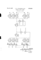
- the figure shows a system for the transmission of carice rier frequencies comprising twelve transmission channels lil-K12, of which for sake of simplicity only the channels Kl, K2, K3 and K11- K12 with the respective networks in the transmitting and receiving stations are illustrated.
- Each of the channels can be connected through closing contacts 1, 3, 5 21, 23 to a respective channel network S1-S12 at the transmitting station.
- Each channel network comprises filter and modulating means in conventional arrangement. These networks are supplied with the particular carrier frequency by oscillators (not shown) and this frequency is modulated by the speech frequency over the contacts.
- the different channel networks are connected through a common lead to a common end amplifier FS over transmission wires to an input amplifier FM at the receiving station. After separation and demodulation in the channel installations Ml-M3, M11-M12, the different transmission channels are again separated from one another, and the speech frequencies are taken off at the output terminals lil-K3, K11-K12 at the right side of the figure.
- the strength of the signal current applied to amplifier FS can be varied by regulating the attenuation lof the network. Consequently, the power gain of the end amplifier can be adjusted in accordance with the level of the output current of the said amplifier. In practice, this adjustment can be carried out by taking off a certain auxiliary current from the transmission medium which current is applied to the network with Variable attenuation for the regulation of the attenuation of the latter.
- this adjustment takes place for instance in such a way that, in the ycase of an increase of the output level from the amplifier FS, said auxiliary current decreases the attenuation of the attenuating network so that the current in the negative feedback branch increases.
- level the attenuation of said network increases and the components of the signal current which reduce the input current of the amplifier FS become smaller as a result of which the output level is increased.
- a generator the output current of which is employed to regulate the amplification in the amplifier FS.
- the strength of this current is regulated in accordance with the output level of the amplifier FS so that an increase in the level of the latter causes a decrease of the current produced by the generator for the regulation of the amplifier and thereby of the power gain, and, conversely, a decrease of the ouput level causes an increase of the amplification of the amplifier.
- part of the output current of vthe amplifier FS is taken off and applied over suitable filtering and rectifying means L1 to a generator G, whose output is controlled by said current in such a way that it is conversely proportional to the level of the output current.
- the generator G produces a noise which may be either a pure sound or a mixture of several sounds, and its output cur-rent is applied to channels within the carrier frequency system which at ⁇ the moment are not buty.
- this current is .applied over the input end of the particular channel networks and over contacts 2, 4, 6 122, 24 to a relay R1R3, R11-R12.
- the contacts with even numbers are breaker contacts which, hence, are closed when the corresponding relay -is deenergized.
- speech is shown coupled to the channels K2 and K11 whereas the channels K1, K3 and K12 are unoccupied ⁇ at the illustrated moment, :that is, not engaged for a speech connection.
- the current supplied by the generator G is applied to lthese unoccupied channels K1, K3 and K12 over the corresponding contacts 2, 6 and 24.
- the generator current passes through the corresponding networks S1, Ss and S12 and is fed from the latter to the amplifier -FS and is finally transmitted over the transmission line.
- the illustrated relays Rl-Ra, R11--R12 can also be employed by means of not shown contacts for busy marking ⁇ of the connecting channels Kr-Ks, K11-K12 used for speech.
- the transmission wires will always ce loaded to the full extent -in that either speech or a noise will be transmitted in each frequency band assigned to the different channels.
- An automatic control system for controlling the transmission level of a multi-channel carrier transmission system comprising a plurality of signal intelligence circuits, filtering ⁇ and modulating means for each circuit, an output yamplier connected with each of said modulating and filtering means, a signal generator, means connecting said generator with the output Iamplifier for controlling the level of the signal produced by said generator, individual switch means interconnected with each circuit, the associated modulating and filtering means and the signal generator, and means responsive to signal ⁇ intelligence 4energies in each circuit to operate the associated switch means to .disconnect the respective cir- 4 i cuit from its associated modulating and filtering means and to connect the output of said generator to the modulating and filtering means of the said respective circuit.
- An automatic control system for controlling the transmission level of a multichannel carrier transmission system comprising a plurality of signal intelligence circuits, filtering and modulating means for each circuit, an output 'amplifier connected with each of said modulating and filtering means, a signal generator, means connecting said generator with the output Iamplifier for changing the level ⁇ of the signal of -said generator inversely of the output of said output amplifier, individual switching means interconnected with each circuit, the associated modulating and filtering means and the signal generator, and means responsive to the interruption of signal intelligence energy in each circuit for op- -erating the associated switch means to disconnect the circuit from itsv associated modulating Iand filtering means and to connect the output of said generator to the modulating and filtering means of ⁇ the said respective circuit.
- each of said switches comprises 'an electromagnetic relay having a plurality of contacts and adapted in its normal position to connect said generator to the associated modulating and ltering means, land ran energizing circuit for each relay responsive to the signal intelligence energy in the associated signal intelligence circuit to energize and actuate ⁇ the relay to disconnect the generator from and Iconnect the signal intelligence circuit to its modulating 'and filtering means.
- each of said switches comprises a relay having a plurality of contacts and adapted in its normal position tol connect said generator to the associated modulating and filtering means, an energizing circuit for each relay responsive to signal 4intelligence energy in the associated signal intelligence circuit 'to energize and actuate the relay to disconnect the generator from and to connect the signal intelligence circuit to its modulating and filtering means, auxiliary contact means on each relay, and a busy signal circuit connected with said auxiliary contacts.
- a multi-channel carrier system for ⁇ the ltransmission of signal intelligence having a plurality of signalling circuits, modulating and filtering means individual to each circuit, an output transmitting amplifier and connections between said amplifier vand each modulating and filter-ing means, means for controlling the output level of said output amplifier comprising a signal generator, means between Asaid signal generator and the output amplifier for controlling the signal level of said generator, individual switch means interconnected with each circui-t, the associated modulating and filtering means land said signal generator, and control means for each switch operable to mov-e the switch to one position to connect its 'associated lcircuit with the modulating Iand filtering means for that circuit for the transmission of signal intelligence and :to move the switch to another position in response to the interruption ⁇ of signal intelligence energy to connect the respective modulating and filtering means with said signal generator.
- a multi-channel carrier system for the transmission of signal intelligence having a plurality of signal transmitting circuits, modulating and filtering means indi.- vidual to cach circuit, an output transmitting amplifier and connections between said amplifier and each modulating and filtering means, means for controlling the output level of said output amplifier comprising a signal generator, means between said signal generator and the output amplifier for controlling the signal level of said generator, and connections between the geenrator and each modulating and iil'tering meansfor impressing the,V
- An automatic control system for controlling the transmitting level of a multi-channel carrier transmission system comprising a plurality of signal intelligence circuits, modulating and filtering means for each circuit, an output amplilier connected with said modulating and iltering means, a signal generator for generating a continuous signal, means connecting said generator with the output amplier for controlling the level of said continuous signal, individual switch means interconnected with each circuit, the associated modulating and filtering means and the signal generator, and means for operating each of said switch means in response to the interruption of signal intelligence in its associated circuit to disconnect the circuit from its respective modulating and ltering means and to connect the output of said generator to the modulating and filtering means of said respective circuit thereby impressing said continuous signal upon the respective circuit when the circuit is not used for the transmission of signal intelligence.
- An automatic control system for controlling the transmitting level of a multi-channel carrier transmission system comprising a plurality of signal transmission circuits, modulating means for each circuit, an output amplilier common to all of said circuits, means for generating a continuous electric signal, control means between said generator and output amplier for controlling the level of said continuous signal, and switch means for impressing said continuous signal upon each modulator during periods of interruption of signal intelligence energy in the circuit associated with that modulator.
- an automatic carrier transmission system for signal intelligence having a transmitting station, a receiving station and a transmission line interconnecting said stations, a plurality of signal carrying circuits, an output amplifier in said transmitting station, a plurality of modulating and filtering means individual to each circuit and connected with said amplifier, switch means individual to and connected with each modulating and liltering means, connections between each circuit and one of said switch means, a signal generator including connections between said generator and earch of said switch means, and switch operating means individual to each switch and responsive to signal intelligence in the associated circuit whereby signal y energy in each circuit will operate said switch in one direction to connect said circuit to its associated modulating means and interruption of said energy will operate the switch in the other direction to disconnect the circuit and connect its associated modulating means to said generator.
Landscapes
- Engineering & Computer Science (AREA)
- Computer Networks & Wireless Communication (AREA)
- Signal Processing (AREA)
- Cable Transmission Systems, Equalization Of Radio And Reduction Of Echo (AREA)
Applications Claiming Priority (1)
| Application Number | Priority Date | Filing Date | Title |
|---|---|---|---|
| SE2782258X | 1950-12-29 |
Publications (1)
| Publication Number | Publication Date |
|---|---|
| US2782258A true US2782258A (en) | 1957-02-19 |
Family
ID=20427255
Family Applications (1)
| Application Number | Title | Priority Date | Filing Date |
|---|---|---|---|
| US262816A Expired - Lifetime US2782258A (en) | 1950-12-29 | 1951-12-21 | Automatic control system |
Country Status (2)
| Country | Link |
|---|---|
| US (1) | US2782258A (fr) |
| FR (1) | FR1047355A (fr) |
Cited By (3)
| Publication number | Priority date | Publication date | Assignee | Title |
|---|---|---|---|---|
| US3045070A (en) * | 1956-08-23 | 1962-07-17 | Ericsson Telefon Ab L M | Multiplex carrier frequency transmission system |
| US3619511A (en) * | 1969-07-17 | 1971-11-09 | North American Rockwell | Data normalizing apparatus |
| US3838230A (en) * | 1971-09-20 | 1974-09-24 | Ericsson Telefon Ab L M | Coaxial cable transmission line |
Citations (2)
| Publication number | Priority date | Publication date | Assignee | Title |
|---|---|---|---|---|
| US2558439A (en) * | 1945-06-09 | 1951-06-26 | Comp Generale Electricite | Pilot signal system of communication |
| US2613279A (en) * | 1949-09-02 | 1952-10-07 | Cie Ind Des Telephones | Ringing and regulating device for carrier current transmission systems |
-
1951
- 1951-12-21 US US262816A patent/US2782258A/en not_active Expired - Lifetime
- 1951-12-28 FR FR1047355D patent/FR1047355A/fr not_active Expired
Patent Citations (2)
| Publication number | Priority date | Publication date | Assignee | Title |
|---|---|---|---|---|
| US2558439A (en) * | 1945-06-09 | 1951-06-26 | Comp Generale Electricite | Pilot signal system of communication |
| US2613279A (en) * | 1949-09-02 | 1952-10-07 | Cie Ind Des Telephones | Ringing and regulating device for carrier current transmission systems |
Cited By (3)
| Publication number | Priority date | Publication date | Assignee | Title |
|---|---|---|---|---|
| US3045070A (en) * | 1956-08-23 | 1962-07-17 | Ericsson Telefon Ab L M | Multiplex carrier frequency transmission system |
| US3619511A (en) * | 1969-07-17 | 1971-11-09 | North American Rockwell | Data normalizing apparatus |
| US3838230A (en) * | 1971-09-20 | 1974-09-24 | Ericsson Telefon Ab L M | Coaxial cable transmission line |
Also Published As
| Publication number | Publication date |
|---|---|
| FR1047355A (fr) | 1953-12-14 |
Similar Documents
| Publication | Publication Date | Title |
|---|---|---|
| GB1261174A (en) | Improvements in or relating to filter networks | |
| US2830257A (en) | Temperature-compensated directcurrent transistor amplifier | |
| US2300415A (en) | Transmission control | |
| US2782258A (en) | Automatic control system | |
| GB583629A (en) | Improvements in or relating to signalling arrangements for electric pulse communication systems | |
| GB1111553A (en) | Radio transmission systems | |
| US3622707A (en) | Multiple channel subscriber loop | |
| US3187104A (en) | Circuit for eliminating attenuation differences in communication lines | |
| US2421333A (en) | Multiplex carrier current communication system with transmission line impedance control means | |
| GB1407088A (en) | Telecommunication systems | |
| US2802055A (en) | Two-way loudspeaker intercommunication system | |
| US2303907A (en) | Multichannel signal transmission | |
| US2816962A (en) | Steady-state signalling using alternating currents | |
| US2468555A (en) | Multiple modulation carrier frequency telephone system | |
| GB2214385A (en) | Radio communication system | |
| US3582788A (en) | Telecommunication system with automatic volume control | |
| US1881801A (en) | Two-way signaling system | |
| US1636053A (en) | Carrier-telegraph repeater circuits | |
| US2319717A (en) | Transmission control in two-way signal wave transmission systems | |
| US1990414A (en) | Circuit for controlling transmission in signaling systems | |
| US1463200A (en) | Ringing arrangement for multiplex circuits | |
| US1570772A (en) | Reduction of distortion in multiplex repeaters | |
| US2766326A (en) | Electrical signalling system | |
| US1675412A (en) | Echo and singing suppressor system | |
| US1674695A (en) | Radio telephone system |