US2858104A - Adjustable gas turbine shroud ring segments - Google Patents
Adjustable gas turbine shroud ring segments Download PDFInfo
- Publication number
- US2858104A US2858104A US408136A US40813654A US2858104A US 2858104 A US2858104 A US 2858104A US 408136 A US408136 A US 408136A US 40813654 A US40813654 A US 40813654A US 2858104 A US2858104 A US 2858104A
- Authority
- US
- United States
- Prior art keywords
- segments
- ring
- outer ring
- bolts
- sleeves
- Prior art date
- Legal status (The legal status is an assumption and is not a legal conclusion. Google has not performed a legal analysis and makes no representation as to the accuracy of the status listed.)
- Expired - Lifetime
Links
- 238000006073 displacement reaction Methods 0.000 description 6
- 244000024671 Brassica kaber Species 0.000 description 4
- RLQJEEJISHYWON-UHFFFAOYSA-N flonicamid Chemical compound FC(F)(F)C1=CC=NC=C1C(=O)NCC#N RLQJEEJISHYWON-UHFFFAOYSA-N 0.000 description 4
- 238000002485 combustion reaction Methods 0.000 description 3
- 238000010276 construction Methods 0.000 description 3
- 238000009413 insulation Methods 0.000 description 2
- 230000002093 peripheral effect Effects 0.000 description 2
- 238000005728 strengthening Methods 0.000 description 2
- 208000035397 Ring chromosome 7 syndrome Diseases 0.000 description 1
- 230000000712 assembly Effects 0.000 description 1
- 238000000429 assembly Methods 0.000 description 1
- 210000005069 ears Anatomy 0.000 description 1
- 230000000694 effects Effects 0.000 description 1
- 239000000446 fuel Substances 0.000 description 1
- 238000003754 machining Methods 0.000 description 1
- 230000001141 propulsive effect Effects 0.000 description 1
- 239000004576 sand Substances 0.000 description 1
- 230000011218 segmentation Effects 0.000 description 1
Images
Classifications
-
- F—MECHANICAL ENGINEERING; LIGHTING; HEATING; WEAPONS; BLASTING
- F01—MACHINES OR ENGINES IN GENERAL; ENGINE PLANTS IN GENERAL; STEAM ENGINES
- F01D—NON-POSITIVE DISPLACEMENT MACHINES OR ENGINES, e.g. STEAM TURBINES
- F01D11/00—Preventing or minimising internal leakage of working-fluid, e.g. between stages
- F01D11/08—Preventing or minimising internal leakage of working-fluid, e.g. between stages for sealing space between rotor blade tips and stator
- F01D11/14—Adjusting or regulating tip-clearance, i.e. distance between rotor-blade tips and stator casing
- F01D11/20—Actively adjusting tip-clearance
- F01D11/22—Actively adjusting tip-clearance by mechanically actuating the stator or rotor components, e.g. moving shroud sections relative to the rotor
-
- F—MECHANICAL ENGINEERING; LIGHTING; HEATING; WEAPONS; BLASTING
- F02—COMBUSTION ENGINES; HOT-GAS OR COMBUSTION-PRODUCT ENGINE PLANTS
- F02C—GAS-TURBINE PLANTS; AIR INTAKES FOR JET-PROPULSION PLANTS; CONTROLLING FUEL SUPPLY IN AIR-BREATHING JET-PROPULSION PLANTS
- F02C3/00—Gas-turbine plants characterised by the use of combustion products as the working fluid
- F02C3/04—Gas-turbine plants characterised by the use of combustion products as the working fluid having a turbine driving a compressor
- F02C3/06—Gas-turbine plants characterised by the use of combustion products as the working fluid having a turbine driving a compressor the compressor comprising only axial stages
Definitions
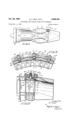
- Fig. 1 is a side elevation of a gas turbine jet engine, partly in section to show a portion of the turbine rotor andshroud ring assembly; ⁇
- Fig. 2 is an enlarged fragmentary section taken along a plane passing through the longitudinal axis of said engine and also showing said portion of the turbine rotor and shroud ring assembly and is also a section taken on the plane 2 2 of Fig. 3;
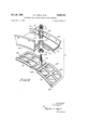
- Fig. 4 is an exploded perspective view of parts of the shroud ring assembly shown in Figs. 2 and 3;
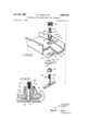
- Fig. 5 is a View similar to Fig. 2 and showing an alternative construction
- Fig. 6 is an exploded perspective view of parts of the assembly shown in Fig. 5.
- air is drawn into an inlet 10 by an axial ow compressor 11 and discharged at high pressure from the compressor into a combustion system 12.
- the combustion system consists of a plurality of chambers into which fuel is introduced and burned in the compressed air, so that the products of combustion are discharged at high velocity and high temperature through a nozzle box 13 into a turbine generally indicated by reference numeral 14.
- the turbine provides the power to drive the compressor 11 through a shaft 15, the exhaust from the turbine being discharged through a tail cone 16 to provide a propulsive thrust.
- the turbine 14 consists of a rotor disc 17 carrying on its peripheral rim a plurality of radially disposed blades 18.
- the turbine revolves within a stator shroud ring assembly generally indicated by reference numeral 19.
- an outer shroud ring 20 has front and rear outwardly directed ilanges 20a and 20b bolted to the nozzle box 13 and tail cone 16 respectively.
- the outer shroud ring has an inwardly directed liange or web 20c at its front end, and at its rear end an inwardly extending annular plate or web 21 is bolted with the tail cone to the flange 20h.
- the outer shroud ring 20 is provided with ⁇ circumferentially -spaced apart holes 20d into which are iitted radially disposed bolt guiding sleeves 22having portions 22a protruding from the outer side of the outer shroud ring.
- Locknuts 23 at the inner side of the outer shroud ring securely hold the bolt guiding sleeves 22 in position and also act as supports for retaining plates 24 which press insulation 25 against the inner face of the outer shroud ring 20.
- the retaining plates 24 are formed with integral locking tabs 26 which are connected by means of wire 27 to the locknuts 23 in order to prevent loosening due to vibration.
- An inner shroud ring concentric with the outer shroud ring and spaced inwardly therefrom consists of a plurality of arcuate segments 28 supported in end-to-end relationship by ⁇ T-bolts 29 the stems of which extend slidably through the sleeves 22.
- the heads of the T-bolts are of H section, and strengthening plates 28a welded to the shroud segments 28 form channels 28b at the ends of the segments engageable with the flanges of the H section and forming seals therewith.
- the heads of the T-bolts bridge together adjacent ends of adjacent segments 28 so that the inner shroud ring is continuous.
- the strengthening plates 28a are longitudinally and transversely dished as at 28e for rigidity, and have side flanges 28d in frictional engagement with the webs 20c and 21. Thus an insulating space 30 is provided between the inner and outer shroud rings.
- each T-bolt 29 is in threaded engagement with a castellated adjusting nut 31 which is held within the outwardly protruding portion 22a of the bolt-guiding sleeve 22 by means of a U-clip or key 32.
- the U-clip passes through tangential slots or grooves 33 in the portion 22a and ts within a circumferential groove 34 in the nut 31, preventing axial displacement of the nut relative to the sleeve 22 but permitting rotation of the nut 31, thereby allowing the T-bolt to be adjustably moved in an axial direction.
- Rotation of the nut 31 is however normally prevented by means of a cotter pin 35 passing through the castellations and one of a pair of holes 29a in the end of the T-bolt. Dislocation of the U-clips 32 is prevented by wiring them in pairs as shown at 36 in Fig. 3.
- the T-bolts 29 are inserted into the sleeves 22 and drawn upwardly only a short distance by the nuts 31 so that the H sections project below the inner edge of the annular web 21.
- the shroud segments 28 are slid into engagement with the H sections and are then drawn radially outwardly by rotation of the adjusting nuts 31.
- the shroud segments are lowered until contact with the rotor blades is established.
- the segments are then retracted a predetermined amount. to allow for the reduction in running clearance which occurs at operating speed due to thermal expansion, centrifugal force and other operating conditions.
- the segmentation of the inner shroud ring eliminates much of the warpage and distortion occurring in conventional shroud rings. Any warpage or distortion that does occur can be substantially eliminated by adjusting one or more of the T-bolts, thus displacing certain seg ments 28 relative to the others.V It is noteworthy that such adjustment can be achieved from outside the outer shroud ring 20 without the necessity of having to dismantle any part of the engine.
- the invention has been described with reference to the ⁇ turbine of a gas turbine engine, but it can obviously be applied to the compressor as well.
- FIG. 5 Another embodiment of the invention which permits positive locking .of the adjusting nuts at any angular position is shownin Figs. 5 and 6.
- the T-bolt 29 passes through a sleeve 22.having an outwardly protruding portion 22a' and yheld in the outer shroud ring 20 by a nut 23, the nut supporting insulation 25 by means of a retaining plate 24.
- the nut and retaining plate are locked by a tab 37 having a recess 37a which receives a pressed-out ear 26 of the retaining plate and having arpair of ears 37b which can be bent down, as shown in Fig. 5, toprevent the nut from turning.
- An adjusting nut 31 threadably engages the upper end ofthe bolt. 29 andhas a slotted frusto-conicallower end portion 31a which, 4with a conical recess 22b in the end of the protrudingportion 22a', forms a collet type fastening, a nut 38 threadably mounted on the outside of the portion 22a being provided to lock the elements 31a', 22a of the fastening together to secure the bolt29 in any desired axial position.
- the ⁇ nut 38- may be held against turning by wiring-it, as as 39, to artab 40a on a member 40 that is held against the outer shroud ring by the sleeve 22.
- the nut 31 and bolt29 may be held against relative rotation by a cotter pin 35.passing between castellations on the nut and through one of .the holes 29a in the bolt.
- a stator ring assembly comprising an outer ring having a plurality of circumferentially spaced apart radial apertures, radially disposedsleeves secured in the apertures, an inner ring lspaced ⁇ radially inwardly from the inner side of the outer ring, the inner ring comprising a plurality of segments movable radially relative to one another, a plurality of radially disposed bolts having heads connecting adjacent segments and ,securely supporting the segments of the inner ring in spaced relationship to the outer ring7 the bolts extending slidably'through the sleeves in the outer ring, nuts rotatably mounted on the sleeves at the outer side'of the ⁇ outer ring, the nuts threadably engaging the bolts whereby rotation of the nuts causes radial movement of the bolts in the sleeves and radial displacement of the segments supported by the bolts, means on the sleeves for securing each nut in the same radial position relative to the outer ring for different
- a stator ring assembly comprising an outer ring having a plurality of circumferentially spaced apart radial apertures, radially disposed sleeves secured in the apertures, the sleeves having portions protruding from the outer side of the outer ring, an inner ring spaced radially inwardly yfrom the inner side of the outer ring, the inner ring comprising a plurality of segments movable radially relative to one another, a plurality of radially disposed bolts having heads connecting adjacent .segments and securely supporting the segments of the inner ring in spaced relationship to the outer ring, the bolts extending slidably through the sleeves in the outer ring, rnuts rotatably mounted on the protruding portions of the sleeves and threadably engaging the bolts whereby rotation of the nuts vcauses radial movement of the bolts in the 'sleeves and radial displacement of the segments supported by the bolts, each nut and proeach protrud
- a stator ring assembly comprising an outer ring having a plurality of circumferentially spaced apart radial apertures, radially disposed sleeves securedfiny the apertures, the'sleeves having portions protruding from the outer side of the outer ring, an inner ring spaced radially inwardly from the inner sideof the outer ring, the inner ring comprising a plurality of segments radially movable relative to one another, aplurality of radially disposed bolts having heads connecting adjacent segments and securely supporting the segments of the inner ring in spaced relationship to the outer ring, the bolts extending slidably through-the sleeves ,in the outer ring, nuts at the outerside of the-outerfringhaving peripheral grooves aligned with grooves in the protruding portions of the sleeves, means in said grooves keying 'the nuts to the protruding-portions for preventing radial displacement vof the nuts While permitting rotation thereof, the ynut
- a stator ring assembly comprising an outer ring, an inner ring spaced radiallyinwardly from the inner side of the outer ring, the inner ring comprising a plurality of segments radially movable relative to one another, a plurality of radially disposed T-bolts ⁇ having heads interlocked with adjacent ends of adjacent segments for bridging together and supporting said segments securely in spaced relationship-to the -outer ring and having stems protruding through the outer ring, and means on the outer side of the outer ring engageable with said stems for adjustably xing-the radial'positions of the T-bolts and hence of the segments relativefto the outer ring.
- a stator ring assembly surrounding the rotor and comprising an outer ring having a plurality ofrcircumferentially spaced apart radial apertures, radially disposed sleeves secured in the apertures, the sleeves having: portions protruding from the outer side of the outer ring, an inner ring spaced radially inwardly from the inner side of the outer ring, the inner ring comprising a plurality of segments arranged in end-to-end-relationship and radially movable relative to one another, a pair of annular webs extending radially inwardly from the edges of the outer ring and with which the segments of the inner ring are in frictional engagement, a plurality of radially disposed T-bolts having heads interlocked with adjacent ends of adjacent segments for bridging together and supporting said segments securely in spaced relationship to the outer ring and having stems extending slidably through the sleeves in the outer ring, nuts
- a stator ring assembly comprising an outer ring, an inner ring spaced radially inwardly from ythe inner side of the outer ring, the inner Aring ncomprising a plurality of segments arranged in end-to-end relationship in the circumferential direction of the inner ring Sand movable radially relative to one another, and a plurality of supporting means supporting the segments securely in spaced relationship to the outer ring, each supporting means bridging together adjacent ends of adjacent segments so that the inner ring is continuous, and each supporting means being adjustably Xed to the outer ring independently of the others for adjustably xing the radial positions of the segments relative to one another.
- a stator ring assembly comprising an outer ring, an inner ring Within the outer ring, the inner ring comprising a plurality of segments arranged in end-to-end relationship in the circumferential direction of the inner ring and movable radially relative to one another, and a plurality of supporting means supporting the segments securely from the outer ring with a space between the outer ring and the segments, the supporting means bridging together adjacent ends of adjacent segments, each supporting means having adjusting and fastening means for xing the supporting means adjustably to the outer ring, the adjusting and fastening means being adjustable from outside the outer ring for varying the radial positions of the segments relative to the outer ring and to one another.
- each supporting means comprises a bolt protruding through the outer ring
- the adjusting and fastening means comprising a rotatable nut threadably engaging the bolt, means holding the nut on the outer ring against movement radially of the outer ring, and nut engaging means for locking the nut against rotation.
- stator ring assembly as claimed in claim 7, wherein the segments are arcuate members having channels at their ends, the supporting means having llanges engageable with said channels of the segments to support the segments and bridge the segments together.
Landscapes
- Engineering & Computer Science (AREA)
- Mechanical Engineering (AREA)
- General Engineering & Computer Science (AREA)
- Chemical & Material Sciences (AREA)
- Combustion & Propulsion (AREA)
- Structures Of Non-Positive Displacement Pumps (AREA)
- Turbine Rotor Nozzle Sealing (AREA)
Priority Applications (3)
| Application Number | Priority Date | Filing Date | Title |
|---|---|---|---|
| US408136A US2858104A (en) | 1954-02-04 | 1954-02-04 | Adjustable gas turbine shroud ring segments |
| CH342040D CH342040A (fr) | 1954-02-04 | 1954-11-02 | Stator de turbo-machine |
| DEC10215A DE954835C (de) | 1954-02-04 | 1954-11-05 | Gehaeusering fuer Kreiselradmaschinen, insbesondere fuer Gasturbinen |
Applications Claiming Priority (1)
| Application Number | Priority Date | Filing Date | Title |
|---|---|---|---|
| US408136A US2858104A (en) | 1954-02-04 | 1954-02-04 | Adjustable gas turbine shroud ring segments |
Publications (1)
| Publication Number | Publication Date |
|---|---|
| US2858104A true US2858104A (en) | 1958-10-28 |
Family
ID=23614997
Family Applications (1)
| Application Number | Title | Priority Date | Filing Date |
|---|---|---|---|
| US408136A Expired - Lifetime US2858104A (en) | 1954-02-04 | 1954-02-04 | Adjustable gas turbine shroud ring segments |
Country Status (3)
| Country | Link |
|---|---|
| US (1) | US2858104A (fr) |
| CH (1) | CH342040A (fr) |
| DE (1) | DE954835C (fr) |
Cited By (20)
| Publication number | Priority date | Publication date | Assignee | Title |
|---|---|---|---|---|
| US3042367A (en) * | 1958-07-17 | 1962-07-03 | Gen Motors Corp | Fluid seal |
| US3062497A (en) * | 1958-11-24 | 1962-11-06 | Ford Motor Co | Gas turbine engine |
| US3093361A (en) * | 1958-07-07 | 1963-06-11 | Bristol Siddeley Engines Ltd | Engines |
| US3209537A (en) * | 1960-05-02 | 1965-10-05 | Bendix Corp | Motive fluid control for a re-expansion gas turbine engine |
| US3391904A (en) * | 1966-11-02 | 1968-07-09 | United Aircraft Corp | Optimum response tip seal |
| US3425665A (en) * | 1966-02-24 | 1969-02-04 | Curtiss Wright Corp | Gas turbine rotor blade shroud |
| FR2521217A1 (fr) * | 1982-02-08 | 1983-08-12 | Jehier Sa | Perfectionnements aux anneaux isolants pour carters de turbines |
| US4925364A (en) * | 1988-12-21 | 1990-05-15 | United Technologies Corporation | Adjustable spacer |
| US5022816A (en) * | 1989-10-24 | 1991-06-11 | United Technologies Corporation | Gas turbine blade shroud support |
| US5145316A (en) * | 1989-12-08 | 1992-09-08 | Rolls-Royce Plc | Gas turbine engine blade shroud assembly |
| US5176496A (en) * | 1991-09-27 | 1993-01-05 | General Electric Company | Mounting arrangements for turbine nozzles |
| FR2817285A1 (fr) * | 2000-11-30 | 2002-05-31 | Snecma Moteurs | Virole interne de stator |
| FR2835563A1 (fr) * | 2002-02-07 | 2003-08-08 | Snecma Moteurs | Agencement d'accrochage de secteurs en arc de cercle de distributeur porteur d'aubes |
| US20040062641A1 (en) * | 2002-09-30 | 2004-04-01 | Pickens John T. | Shim lock/pin anti-rotation bumper design |
| EP1505259A1 (fr) * | 2003-08-08 | 2005-02-09 | ROLLS-ROYCE plc | Ensemble pour le montage d'un composant non rotatif d'une turbine à gaz |
| EP2034133A3 (fr) * | 2007-09-07 | 2011-02-23 | MTU Aero Engines GmbH | Segment d'étanchéité ajustable pour turbine à gaz |
| US20140109594A1 (en) * | 2012-10-23 | 2014-04-24 | General Electric Company | Deformable Mounting Assembly |
| US9416671B2 (en) | 2012-10-04 | 2016-08-16 | General Electric Company | Bimetallic turbine shroud and method of fabricating |
| JP2017537263A (ja) * | 2014-12-09 | 2017-12-14 | サフラン・エアクラフト・エンジンズ | タービンエンジンの可変ピッチベーンの段のための制御リング |
| US11486271B1 (en) * | 2021-10-15 | 2022-11-01 | Pratt & Whitney Canada Corp. | Adjustable mount for engine accessory |
Families Citing this family (10)
| Publication number | Priority date | Publication date | Assignee | Title |
|---|---|---|---|---|
| BE556215A (fr) * | 1956-03-28 | 1957-04-15 | ||
| GB1051244A (fr) * | 1962-10-09 | |||
| US4163366A (en) * | 1977-05-23 | 1979-08-07 | Avco Corporation | Apparatus for disposal of leaking fluids in a turbofan engine |
| US4131388A (en) * | 1977-05-26 | 1978-12-26 | United Technologies Corporation | Outer air seal |
| GB2115487B (en) * | 1982-02-19 | 1986-02-05 | Gen Electric | Double wall compressor casing |
| US5104287A (en) * | 1989-09-08 | 1992-04-14 | General Electric Company | Blade tip clearance control apparatus for a gas turbine engine |
| US5056988A (en) * | 1990-02-12 | 1991-10-15 | General Electric Company | Blade tip clearance control apparatus using shroud segment position modulation |
| US5238365A (en) * | 1991-07-09 | 1993-08-24 | General Electric Company | Assembly for thermal shielding of low pressure turbine |
| FR2683851A1 (fr) * | 1991-11-20 | 1993-05-21 | Snecma | Turbomachine equipee de moyens facilitant le reglage des jeux du stator entree stator et rotor. |
| US5271713A (en) * | 1992-10-05 | 1993-12-21 | Deere & Company | Adjustable inlet for a harvester fan |
Citations (12)
| Publication number | Priority date | Publication date | Assignee | Title |
|---|---|---|---|---|
| US890635A (en) * | 1906-02-14 | 1908-06-16 | Gen Electric | Elastic-fluid turbine. |
| GB190926383A (en) * | 1909-07-20 | 1910-05-05 | Chantiers De Bretagne Anciens | Improvements in or relating to Turbines. |
| US1304412A (en) * | 1919-05-20 | Junta toyoeawa | ||
| US1352276A (en) * | 1918-12-06 | 1920-09-07 | Gen Electric | Elastic-fluid turbine |
| DE436567C (de) * | 1924-01-19 | 1926-11-04 | Waggon Und Maschb Akt Ges | Leitschaufelkranz fuer Dampf- und Gasturbinen |
| GB600057A (en) * | 1945-12-21 | 1948-03-30 | Power Jets Res & Dev Ltd | Improvements in or relating to the mounting of blades in axial flow compressors, turbines, or the like |
| US2447942A (en) * | 1944-12-05 | 1948-08-24 | Rateau Soc | Turbine distributor and nozzle |
| US2544538A (en) * | 1948-12-01 | 1951-03-06 | Wright Aeronautical Corp | Liner for hot gas chambers |
| GB679916A (en) * | 1949-04-29 | 1952-09-24 | Geoffrey Bertram Robert Feilde | Improvements in gas turbines |
| DE852789C (de) * | 1951-02-08 | 1952-10-20 | Maschf Augsburg Nuernberg Ag | Leitschaufeltraeger fuer Axialturbinen |
| US2622790A (en) * | 1946-02-25 | 1952-12-23 | Power Jets Res & Dev Ltd | Bladed stator assembly primarily for axial flow compressors |
| GB689270A (en) * | 1949-12-13 | 1953-03-25 | Rateau Soc | Improvements in axial flow turbines or compressors |
Family Cites Families (1)
| Publication number | Priority date | Publication date | Assignee | Title |
|---|---|---|---|---|
| FR981975A (fr) * | 1943-05-21 | 1951-06-01 | Rateau Soc | Perfectionnement aux turbines à gaz |
-
1954
- 1954-02-04 US US408136A patent/US2858104A/en not_active Expired - Lifetime
- 1954-11-02 CH CH342040D patent/CH342040A/fr unknown
- 1954-11-05 DE DEC10215A patent/DE954835C/de not_active Expired
Patent Citations (12)
| Publication number | Priority date | Publication date | Assignee | Title |
|---|---|---|---|---|
| US1304412A (en) * | 1919-05-20 | Junta toyoeawa | ||
| US890635A (en) * | 1906-02-14 | 1908-06-16 | Gen Electric | Elastic-fluid turbine. |
| GB190926383A (en) * | 1909-07-20 | 1910-05-05 | Chantiers De Bretagne Anciens | Improvements in or relating to Turbines. |
| US1352276A (en) * | 1918-12-06 | 1920-09-07 | Gen Electric | Elastic-fluid turbine |
| DE436567C (de) * | 1924-01-19 | 1926-11-04 | Waggon Und Maschb Akt Ges | Leitschaufelkranz fuer Dampf- und Gasturbinen |
| US2447942A (en) * | 1944-12-05 | 1948-08-24 | Rateau Soc | Turbine distributor and nozzle |
| GB600057A (en) * | 1945-12-21 | 1948-03-30 | Power Jets Res & Dev Ltd | Improvements in or relating to the mounting of blades in axial flow compressors, turbines, or the like |
| US2622790A (en) * | 1946-02-25 | 1952-12-23 | Power Jets Res & Dev Ltd | Bladed stator assembly primarily for axial flow compressors |
| US2544538A (en) * | 1948-12-01 | 1951-03-06 | Wright Aeronautical Corp | Liner for hot gas chambers |
| GB679916A (en) * | 1949-04-29 | 1952-09-24 | Geoffrey Bertram Robert Feilde | Improvements in gas turbines |
| GB689270A (en) * | 1949-12-13 | 1953-03-25 | Rateau Soc | Improvements in axial flow turbines or compressors |
| DE852789C (de) * | 1951-02-08 | 1952-10-20 | Maschf Augsburg Nuernberg Ag | Leitschaufeltraeger fuer Axialturbinen |
Cited By (28)
| Publication number | Priority date | Publication date | Assignee | Title |
|---|---|---|---|---|
| US3093361A (en) * | 1958-07-07 | 1963-06-11 | Bristol Siddeley Engines Ltd | Engines |
| US3042367A (en) * | 1958-07-17 | 1962-07-03 | Gen Motors Corp | Fluid seal |
| US3062497A (en) * | 1958-11-24 | 1962-11-06 | Ford Motor Co | Gas turbine engine |
| US3209537A (en) * | 1960-05-02 | 1965-10-05 | Bendix Corp | Motive fluid control for a re-expansion gas turbine engine |
| US3425665A (en) * | 1966-02-24 | 1969-02-04 | Curtiss Wright Corp | Gas turbine rotor blade shroud |
| US3391904A (en) * | 1966-11-02 | 1968-07-09 | United Aircraft Corp | Optimum response tip seal |
| FR2521217A1 (fr) * | 1982-02-08 | 1983-08-12 | Jehier Sa | Perfectionnements aux anneaux isolants pour carters de turbines |
| US4925364A (en) * | 1988-12-21 | 1990-05-15 | United Technologies Corporation | Adjustable spacer |
| US5022816A (en) * | 1989-10-24 | 1991-06-11 | United Technologies Corporation | Gas turbine blade shroud support |
| US5145316A (en) * | 1989-12-08 | 1992-09-08 | Rolls-Royce Plc | Gas turbine engine blade shroud assembly |
| US5176496A (en) * | 1991-09-27 | 1993-01-05 | General Electric Company | Mounting arrangements for turbine nozzles |
| US6679679B1 (en) | 2000-11-30 | 2004-01-20 | Snecma Moteurs | Internal stator shroud |
| FR2817285A1 (fr) * | 2000-11-30 | 2002-05-31 | Snecma Moteurs | Virole interne de stator |
| US7290982B2 (en) | 2002-02-07 | 2007-11-06 | Snecma Moteurs | Arrangement for the attachment of distributor sectors supporting vanes around an arc of a circle |
| EP1335113A1 (fr) * | 2002-02-07 | 2003-08-13 | Snecma Moteurs | Agencement d'accrochage de secteurs en arc de cercle de distributeur porteur d'aubes |
| FR2835563A1 (fr) * | 2002-02-07 | 2003-08-08 | Snecma Moteurs | Agencement d'accrochage de secteurs en arc de cercle de distributeur porteur d'aubes |
| US20050042081A1 (en) * | 2002-02-07 | 2005-02-24 | Snecma Moteurs | Arrangement for the attachment of distributor sectors supporting vanes around an arc of a circle |
| US20040062641A1 (en) * | 2002-09-30 | 2004-04-01 | Pickens John T. | Shim lock/pin anti-rotation bumper design |
| AU2003248373B2 (en) * | 2002-09-30 | 2005-02-24 | United Technologies Corporation | Shim lock/pin anti-rotation bumper design |
| US6884025B2 (en) * | 2002-09-30 | 2005-04-26 | United Technologies Corporation | Shim lock/pin anti-rotation bumper design |
| EP1505259A1 (fr) * | 2003-08-08 | 2005-02-09 | ROLLS-ROYCE plc | Ensemble pour le montage d'un composant non rotatif d'une turbine à gaz |
| EP2034133A3 (fr) * | 2007-09-07 | 2011-02-23 | MTU Aero Engines GmbH | Segment d'étanchéité ajustable pour turbine à gaz |
| US9416671B2 (en) | 2012-10-04 | 2016-08-16 | General Electric Company | Bimetallic turbine shroud and method of fabricating |
| US20140109594A1 (en) * | 2012-10-23 | 2014-04-24 | General Electric Company | Deformable Mounting Assembly |
| US9322334B2 (en) * | 2012-10-23 | 2016-04-26 | General Electric Company | Deformable mounting assembly |
| JP2017537263A (ja) * | 2014-12-09 | 2017-12-14 | サフラン・エアクラフト・エンジンズ | タービンエンジンの可変ピッチベーンの段のための制御リング |
| US10662805B2 (en) * | 2014-12-09 | 2020-05-26 | Snecma | Control ring for a stage of variable-pitch vanes for a turbine engine |
| US11486271B1 (en) * | 2021-10-15 | 2022-11-01 | Pratt & Whitney Canada Corp. | Adjustable mount for engine accessory |
Also Published As
| Publication number | Publication date |
|---|---|
| CH342040A (fr) | 1959-10-31 |
| DE954835C (de) | 1956-12-20 |
Similar Documents
| Publication | Publication Date | Title |
|---|---|---|
| US2858104A (en) | Adjustable gas turbine shroud ring segments | |
| US3814539A (en) | Rotor sealing arrangement for an axial flow fluid turbine | |
| US4274805A (en) | Floating vane support | |
| US5302086A (en) | Apparatus for retaining rotor blades | |
| EP1149986B1 (fr) | Boítier de turbine | |
| US2795108A (en) | Combustion apparatus | |
| US2488867A (en) | Nozzle-guide-vane assembly for gas turbine engines | |
| EP0161203B1 (fr) | Support d'aubes directrices de la premières rangée d'une turbine | |
| EP0202188B1 (fr) | Assemblage de rotor de turbine à deux étages | |
| US2548886A (en) | Gas turbine power plant with axial flow compressor | |
| US5161944A (en) | Shroud assemblies for turbine rotors | |
| GB2081392A (en) | Turbomachine seal | |
| US7013652B2 (en) | Gas turbo set | |
| US3067983A (en) | Turbine mounting construction | |
| CA2065639A1 (fr) | Canal d'amenee tronconique calibre pour refroidissement d'anneau de renforcement de moteur de turbine a gaz | |
| US4747750A (en) | Transition duct seal | |
| EP3670843B1 (fr) | Section de turbine à gaz dotée d'aubes composites à matrice céramique | |
| GB2260789A (en) | Mounting arrangements for turbine nozzles. | |
| US5913660A (en) | Gas turbine engine fan blade retention | |
| US3455537A (en) | Air-cooled turbine rotor self-sustaining shroud plate | |
| US7329096B2 (en) | Machine tooled diaphragm partitions and nozzles | |
| US3019035A (en) | Mounting mechanism for labyrinth seal disc | |
| US10024189B2 (en) | Flow sleeve for thermal control of a double-walled turbine shell and related method | |
| EP1040256B1 (fr) | Support pour un ensemble stator de turbine | |
| US2594808A (en) | Means for supporting the nozzles of the combustion chambers of internal-combustion turbines |