US2905979A - Rollers for drawing mechanisms of textile spinning machines - Google Patents
Rollers for drawing mechanisms of textile spinning machines Download PDFInfo
- Publication number
- US2905979A US2905979A US633552A US63355257A US2905979A US 2905979 A US2905979 A US 2905979A US 633552 A US633552 A US 633552A US 63355257 A US63355257 A US 63355257A US 2905979 A US2905979 A US 2905979A
- Authority
- US
- United States
- Prior art keywords
- shaft
- roll
- rolls
- operative position
- axially
- Prior art date
- Legal status (The legal status is an assumption and is not a legal conclusion. Google has not performed a legal analysis and makes no representation as to the accuracy of the status listed.)
- Expired - Lifetime
Links
- 238000009987 spinning Methods 0.000 title description 12
- 239000004753 textile Substances 0.000 title description 12
- 230000007246 mechanism Effects 0.000 title description 10
- 239000011796 hollow space material Substances 0.000 description 30
- 238000004140 cleaning Methods 0.000 description 13
- 238000005192 partition Methods 0.000 description 10
- 239000000126 substance Substances 0.000 description 8
- 230000006835 compression Effects 0.000 description 7
- 238000007906 compression Methods 0.000 description 7
- 230000008878 coupling Effects 0.000 description 5
- 238000010168 coupling process Methods 0.000 description 5
- 238000005859 coupling reaction Methods 0.000 description 5
- 238000006073 displacement reaction Methods 0.000 description 5
- 230000008093 supporting effect Effects 0.000 description 5
- 229910000639 Spring steel Inorganic materials 0.000 description 2
- 230000013707 sensory perception of sound Effects 0.000 description 2
- 208000036366 Sensation of pressure Diseases 0.000 description 1
- 230000000875 corresponding effect Effects 0.000 description 1
- 230000000694 effects Effects 0.000 description 1
- 230000006870 function Effects 0.000 description 1
- 239000002184 metal Substances 0.000 description 1
- 230000004048 modification Effects 0.000 description 1
- 238000012986 modification Methods 0.000 description 1
- 239000002245 particle Substances 0.000 description 1
- 239000012858 resilient material Substances 0.000 description 1
- 230000000717 retained effect Effects 0.000 description 1
- 230000000087 stabilizing effect Effects 0.000 description 1
- 230000000153 supplemental effect Effects 0.000 description 1
Images
Classifications
-
- D—TEXTILES; PAPER
- D01—NATURAL OR MAN-MADE THREADS OR FIBRES; SPINNING
- D01H—SPINNING OR TWISTING
- D01H5/00—Drafting machines or arrangements ; Threading of roving into drafting machine
- D01H5/18—Drafting machines or arrangements without fallers or like pinned bars
- D01H5/70—Constructional features of drafting elements
- D01H5/74—Rollers or roller bearings
-
- D—TEXTILES; PAPER
- D01—NATURAL OR MAN-MADE THREADS OR FIBRES; SPINNING
- D01H—SPINNING OR TWISTING
- D01H2700/00—Spinning or twisting machines; Drafting devices
- D01H2700/245—Conception or fabrication of drafting cylinders
Definitions
- This invention relates to rollers for the drawing mechanisms of textile spinning machines and more particularly, is directed to top weighting rollers of the kind wherein a roll is mounted at each end of a shaft to rotate with the latter and the shaft rotates in a stationary bearing housing disposed axially between the rolls with the housing having end portions which accommodate anti-friction bearings and extend axially into hollow spaces or recesses of the rolls.
- top weighting rollers of the kind having a roll mounted on each end of a shaft for rotation with the latter relative to a fixed bearing housing that extends around the shaft between the rolls and into hollow spaces or recesses of the latter, and wherein provision is made for the convenient removal of dirt, fibres and other foreign substances from such hollow spaces or recesses of the rolls without requiring the removal of the latter from the shaft.
- cleaning out of the hollow recesses or spaces of the rolls is facilitated by making the rolls axially movable along the shaft between operative positions, where the rolls are constrained to rotate with the shaft and have the end portions of the bearing housing extending into their hollow spaces or recesses, and inoperative positions, where the rolls are displaced axially away from the end portions of the bearing housing to expose the openings to the hollow spaces or recesses of the rolls, and by providing resilient means for urging the rolls axially to their operative positions.
- the roll can be manually displaced axially away from the end portion of the bearing housing so that access can be had to the hollow space or recess and the foreign substances can then be easily withdrawn therefrom.
- the roll may be released to be returned to its operative position by the resilient means acting thereagainst.
- each roll is caused to rotate with the shaft by a driving pin which is fixedly carried by the shaft and engages in a groove of the roll when the latter is in its operative position.
- the driving pin conveniently acts as a stop to limit the axial movement of the roll by the resilient means urging the roll to its operative position.
- each roll is caused to rotate with the shaft by a radial projection on a disc fixed to the shaft and engaging in an axial groove formed in the body or shell of the roll, and axial movement of the roll by the resilient means in the direction toward its operative position is limited by a ring carried by the roll and engageable against the fixed disc in the operative position of the roll.
- the disc fixed on the shaft to cooperate with the roll in causing rotation of the latter with the shaft and in limiting the axial movement of the roll by the associated resilient means performs the additional function of stabilizing the related roll to prevent tilting of the axis of the latter relative to the axis of the shaft.
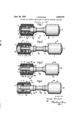
- Fig. 1 is a side elevational view of a roller for the drawing mechanism of a textile spinning machine constructed in accordance with one embodiment of the present invention, and which is shown with the rolls thereof in their operative positions and with one of the rolls being broken away and shown in axial section;
- Fig. 2 is a view similar to that of Fig. l, but with the rolls being shown in their inoperative or cleaning positions;
- Fig. 3 is a view similar to that of Fig. 1, but showing a roller constructed in accordance with another embodiment of the invention.
- Fig. 4 is a view similar to that of Fig. 3, but showing the rolls of the illustrated roller in their inoperative or cleaning positions.
- a roller embodying the present invention and particularly useful as a top weighting roller in drawing mechanisms of textile spinning machines, is there illustrated and generally identified by the reference letter R.
- the roller R includes a non-rotatable bearing housing 1 having a shaft 2 extending axially therethrough and rotatably supported by suitable anti-friction bearingslnot shown), for example, ball hearings or roller bearings, disposed in enlarged end portions of the bearing housing 1, and two rolls which are generally identified by the reference letters r and are mounted on the end portions of shaft 2 projecting from hearing housing 1.
- Each of the rolls r includes a metal shell or body 3 having a cylindrical portion 18 with a resilient cover 4 of rubber or the like on the outer surface thereof and with a radial wall or partition 19 extending across the interior of cylindrical portion 18 intermediate the ends of the latter to divide the interior of the shell 3 into hollow spaces or recesses 7 and 20 which open axially at the opposite ends of the roll.
- the radial wall 19 has a central boss 9 at the side thereof facing away from bearing housing 1 and the wall 19 and boss 9 are formed with a cen tral bore extending therethrough and slidably receiving the shaft 2 so that each roll r can be axially displaced relative to the shaft between an operative position (Fig.
- Fig. 1 where the adjacent enlarged end portion of housing 1 extends into the hollow space or recess 7, and an inoperative or cleaning position (Fig. 2), where the roll is axially displaced away from the bearing housing to facilitate access to the hollow space 7 for cleaning out dirt, fibres and other foreign substances from such space.
- each of the rolls r is rotationally fixed relative to the shaft 2, when in its operative position, by a pin 5 extending diametrically through the shaft 2 and having its opposite end portions projecting from the shaft for engagement in a diametrically extending groove 6 formed in the surface of wall 19 facing toward the bearing housing 1.
- the pin 5 associated with each roll r is located along the shaft 2 so that, when the pin 5 is received in the recess 6, the related roll will be in its operative position.
- pin 5 in groove 6 will provide a rotational coupling between the roll r and the shaft 2, and will also prevent the axial movement of the roll beyond its operative position in the direction toward the bearing housing so that the pin 5 can also be considered a stop.
- a radially outward directed flange or ring 8 is provided on each of the enlarged end portions of bearing housing 1 and has an outer diameter only slightly smaller than the inner diameter of the hollow space 7 of the related roll r, the flange 8 being axially located to extend across, and substantially close, the radial clearance between the cylindrical portion 18 of body 3 and the enlarged end portion of housing 1 when the roll is in its operative position (Fig. 1).
- a helical compression spring 12 is arranged within the interior space 20 of each roll and bears, at its opposite ends, against the surface of wall 19 facing away from the bearing housing and against an annular abutment or pres sure plate 11 on the shaft 2, respectively.
- a split ring 10 of resilient material for example, spring steel, is engageable in an annular groove of shaft 2 and is engaged by pressure plate 11 to stop the axial movement of the latter toward the adjacent end of shaft 2 so that the helical spring 12 acts to yieldably urge the related roll axially along the shaft to the operative position of the roll (Fig. 1).
- the pressure plate 11 has an annular groove at the side thereof facing toward wall 19 and opening axially and radially outward to receive and seat the adjacent end of spring 12, while the opposite end of the latter seats around the boss 9 so that the spring 12 is centered within the space 20 of the roll. Further, all dirt, fibres and other foreign substances are positively excluded from the space 20 of each roll 1' by a cover plate 13 extending across the outer end of the shell or body 3.
- roller Ra there illustrated is generally similar to the roller R described above with reference to Figs. 1 and 2 and that the parts of the roller Ra are identified by the same reference characters used in connection with the correspond ing parts of roller R, but with the letter a appended thereto.
- the roller Ra differs from the first described embodiment only with respect to the means for causing rotation of the rolls ra with the shaft 2a and for limiting the axial displacement of each of the rolls by the related spring 12a to its operative position.
- each of the springs 12a at its end remote from wall 19a of the related roll, abuts against a disc 14 which is fixed on shaft 2a, for example, by a set screw (not shown), and the periphery of disc 14 fits closely within space 20a and has a radial projection 15 that is slidably received in a longitudinal groove 16 formed in the inner surface of cylindrical portion 18a within space 20a, thereby to prevent rotation of the roll relative to shaft 2a.
- the projection 15 and the groove 16 may have wedge-shaped cross-sections in the plane perpendicular to the axis of shaft 2a.
- the disc 14 serves as a supplemental bearing for the related roll on the shaft 2a which, in the operative position of the roll (Fig. 3), is spaced axially from the bearing of wall 19a and boss 9a on the shaft, thereby to effectively prevent tilting of the axis of the roll relative to the axis of the shaft.
- each roll ra has a split ring 17, for example, of spring steel, disposed in an annular, radially inward opening groove in the inner surface of cylindrical portion 18a adjacent the open end of space 20a for engagement against the disc 14 (Fig. 3) when the related roll is in its operative position, thereby to act as a stop resisting further axial displacement of the roll by spring 12a.
- the rolls ra are normally retained in their operative positions by the related springs 12a and are held against rotation relative to the shaft 2a by the cooperative engagement of projection 15 in groove 16 of each roll, and that, whenever the spaces 7a of the rolls become clogged with dirt, fibres or other foreign substances, the rolls can be axially displaced away from the enlarged end portions of housing 1 and the flanges 8a thereon, as in Fig. 4, to permit access to the spaces 7a for cleaning out the latter.
- the hollow spaces of the rolls can be cleaned out without requiring removal thereof from the shaft 2 or 2a.
- a roller for the drawing mechanism of textile spinning frames comprising a rotatably supported shaft, rolls mounted on the opposite end portions of said shaft to be slidable axially along the latter between inner or operative and outer or inoperative positions or vice versa, each roll having a first hollow space axially opening around the shaft at one end of the respective roll toward the first hollow space in the other roll, means preventing rotation of said rolls relative to said shaft at least in said operative positions of the rolls, and resilient means urging each roll, while out of the respective operative position, back to the respective operative position.
- a roller as in claim 1, wherein said means preventing rotation of the rolls relative to the shaft includes a driving pin fixedly carried by said shaft for each of said rolls, each of said rolls having a groove in a portion thereof for receiving said driving pin to form a rotational coupling between the related roll and said shaft.
- each of said rolls includes a shell having a radial surface facing in the direction of movement of the roll toward said operative position
- said means preventing rotation of the rolls relative to the shaft includes a pin extending diametrica'lly through said shaft for each of said rolls, said radial surface having a diametrically extending groove therein receiving the related pin when the roll is in the operative position to form a rotational coupling between the shaft and the related roll and to limit the axial displacement of the roll by said resilient means at said operative position.
- said resilient means urging the rolls axially to said operative positions includes a helical compression spring associated with each of said rolls and acting, at one end, against the related roll in the direction toward the operative position of the latter, and an annular pressure plate for each spring releasably held on said shaft and abutting against the other end of the related spring.
- a roller as in claim 1, wherein said means preventing rotation of the rolls relative to the shaft includes a disc fixed to said shaft for each of the rolls and having a radial projection on the periphery thereof, each of said rolls having a second hollow space opening at one end in the axial direction away from the first hollow space and receiving the related disc, each of said rolls further having a radially inward opening groove extending parallel to the axis thereof in the surface of said hollow space and slidably receiving said radial projection so that the latter and said groove form a rotational coupling between the related roll and said shaft.
- a roller as in claim 5, wherein said resilient means urging the rolls axially to said operative positions includes a helical compression spring in said second hollow space of each roll and abutting, at its opposite ends, against said disc and the other end of said hollow space.
- a roller as in claim 6, further comprising a removable stop within said second hollow space adjacent said one end of the latter and engageable axially against said disc to limit the movement of the related roll by the related spring to said operative position.
- a roller for the drawing mechanism of textile spinning machines comprising a shaft, a bearing housing having said shaft extending therethrough and rotatably supporting the latter, two rolls mounted on the opposite end portions of said shaft and each including a body having hollow spaces opening axially at the opposite ends thereof around said shaft and a central partition separating said hollow spaces and seating on said shaft, each of said rolls being axially slidable on said shaft between an operative position, where an adjacent end portion of said bearing housing extends into one of said hollow spaces, and an inoperative cleaning position, where access canbe had to said one hollow space through the open end of the latter, means preventing rotation of each of said rolls relative to said shaft at least in the operative position of the roll, and resilient means yieldably urging each of said rolls axially relative to said shaft in the direction toward said operative position of the roll.
- a roller for the drawing mechanism of textile spinning machines comprising a shaft, a bearing housing having said shaft extending thereth-rough and rotatably sup porting the latter, two rolls mounted on the opposite end portions of said shaft and each including a body having hollow spaces opening axially at the opposite ends thereof around said shaft and a central partition sepanating said hollow spaces and seating on said shaft, each of said rolls being axially slidable on said shaft between an operative position, where an adjacent end portion of said bearing housing extends into one of said hollow spaces, and an inoperative cleaning position, where access can be had to said one hollow space through the open end of the latter, an annular abutment on said shaft within the other of said hollow spaces of each roll, a helical compression spring in said other hollow space of each roll abutting, at its opposite ends against said annular abutment and said central partition, respectively, to yieldably urge the related roll in the axial direction toward said operative position, and means preventing rotation '6 of each of said rolls relative to said shaft at least in the
- a roller for the drawing mechanism of textile spinning machines comprising a shaft, a bearing housing having said shaft extending therethrough and rotatably supporting the latter, two rolls mounted on the opposite end portions of said shaft and each including a body having hollow spaces opening axially at the opposite ends thereof around said shaft and a central partition separating said hollow spaces and seat-ing on said shaft, each of said rolls being axially slidable on said shaft between an operative position, where an adjacent end portion of said bearing housing extends into one of said hollow spaces, and an inoperative cleaning position, where access can be had to said one hollow space through the open end of the latter, an annular abutment on said shaft within the other of said hollow spaces of the roll, a helical compression spring in said other hollow space of each roll abutting, at its opposite ends against said annular abutment and said central partition, respectively, to yieldably urge the related roll in the axial direction toward said operative position, and a diametrically extending pin carried by said shaft within said one hollow space of each of said rolls, said
- a roller as in claim 10 wherein said shaft has an annular, radially outward opening groove for each of said abutments, and a removable ring in said annular groove engaging the related abutment at the side of the latter facing away from the related spring to transmit the thrust of the latter to said shaft, so that, upon removal of said ring, said abutment and spring can be withdrawn to permit axial removal of the related roll from said shaft.
- a roller for the drawing mechanism of textile spinning machines comprising a shaft, a bearing housing having said shaft extending therethrou-gh and rotatably supporting the latter, two rolls mounted on the opposite end portions of said shaft and each including a body having hollow spaces opening axially at the opposite ends thereof around said shaft and a central partition separating said hollow spaces and seating on said shaft, each of said rolls being axially slidable on said shaft between an operative position, where an adjacent end portion of said bearing housing extends into one of said hollow spaces, and an inoperative cleaning position, where access can be had to said one hollow space through the open end of the latter, an annular abutment on said shaft within the other of said hollow spaces of each roll, a helical compression spring in said other hollow space of each roll abutting, at its opposite ends against said annular abutment and said central partition, respectively, to yieldably urge the related roll in the axial direction toward.
- each of said rolls having an axially extending, radially inward opening groove within said other hollow space thereof, and said annular abutment having a radially extending projection on the periphery thereof slidably received in said axially extending groove of the related roll to prevent rotation of the latter with respect to said shaft.
- each of said rolls further has an annular, radially inward opening groove adjaeent the open end of said other hollow space thereof, and a resilient split ring received in said annular groove and engageable axially against said annular abutment to limit the axial displacement of the roll by the related helical compression spring to said operative position.
- a roller as in claim 1 a bearing housing having the shaft axial-1y extending therethrough and supporting the latter, the bearing housing having enlarged end portions, each end portion being provided with a radially outward directed flange and being adapted to extend at least partly into one of the first hollow spaces, said flange closing the hollow space of the related roll, with the latter in its operative position.
- a roller for the drawing mechanism of textile spinning frames comprising a rotatably supported shaft, rolls mounted on the opposite end portions of said shaft to be slidable axially along the latter between inner or operative and outer or inoperative positions or vice versa, each roll having a fir s-t and a second hollow space, each of the hollow spaces opening axially around the shaft at one end of the respective roll away from the other hollow space, means preventing rotation of said rolls relative to said shaf-t at least in said operative position of the rolls, and allowing the rolls to be slid between said positions, and resilient means urging each roll, while out of its operative position, back to its operative position.
Landscapes
- Engineering & Computer Science (AREA)
- Mechanical Engineering (AREA)
- Textile Engineering (AREA)
- Spinning Or Twisting Of Yarns (AREA)
Description
Sept. 29, 1959 J.- STEICHELE 3 9 ROLLERS FOR DRAWING MECHANISMS OF TEXTILE SPINNING MACHINES Filed Jan. 11, 1957 Fig.1
15 16 71 Fig.3
8 I la:
75 16 i Fig 4 41 'INVENTOR .70.; e a/r f/e/r/re/e United States Patent ROLLERS FOR DRAWING MECHANISMS OF TEXTILE SPINNING MACHINES Joseph Steichele, Stuttgart-Weilimdorf, Germany, assignor to SKF Kugellagerfabriken Gesellschaft mit beschrankter Haftung, Schweinfurt, Germany, a company of Germany Application January 11, 1957, Serial No. 633,552
Claims priority, application Germany January 25, 1956 16 Claims. (Cl. 19142) This invention relates to rollers for the drawing mechanisms of textile spinning machines and more particularly, is directed to top weighting rollers of the kind wherein a roll is mounted at each end of a shaft to rotate with the latter and the shaft rotates in a stationary bearing housing disposed axially between the rolls with the housing having end portions which accommodate anti-friction bearings and extend axially into hollow spaces or recesses of the rolls.
In the existing top weighting rollers of the described character, dirt, fibres and other foreign substances that enter the hollow spaces or recesses of the rolls around the end portions of the bearing housing cannot be easily removed therefrom. In order to clean such existing rolls, it is generally necessary to remove the latter from the rotatable shaft on which they are fixedly mounted, and removal of the rolls is usually time consuming and inconvenient. Further, the rolls mounted on the ends of the rotatable shaft include relatively thin-walled shells that may be damaged during removal from the shaft so that the rolls cannot then be reused. In order to avoid the difficulties mentioned above that attend the removal of the rolls to permit cleaning out of the hollow spaces or recesses thereof, it has been proposed to provide labyrinth seals between the bearing housing and the shells of the rolls, thereby to exclude dirt, fibres and other foreign particles from the hollow spaces or recesses of the rolls, for example, as shown in United States Letters Patent No. 2,740,164, issued April 3, 1956 to E. F. Schmid and Julius Raible. However, such seals are not completely effective and, after a period of time, the hollow spaces of the rolls collect substantial quantities of dirt, fibres and the like, which must be cleaned out to avoid fouling of the anti-friction bearings.
Accordingly, it is an object of the present invention to provide top weighting rollers of the kind having a roll mounted on each end of a shaft for rotation with the latter relative to a fixed bearing housing that extends around the shaft between the rolls and into hollow spaces or recesses of the latter, and wherein provision is made for the convenient removal of dirt, fibres and other foreign substances from such hollow spaces or recesses of the rolls without requiring the removal of the latter from the shaft.
In accordance with an aspect of this invention, cleaning out of the hollow recesses or spaces of the rolls is facilitated by making the rolls axially movable along the shaft between operative positions, where the rolls are constrained to rotate with the shaft and have the end portions of the bearing housing extending into their hollow spaces or recesses, and inoperative positions, where the rolls are displaced axially away from the end portions of the bearing housing to expose the openings to the hollow spaces or recesses of the rolls, and by providing resilient means for urging the rolls axially to their operative positions. Thus, when dirt, fibres or other foreign substances have entered the hollow space or recess of a roll around the adjacent end portion of the bearing hous- 2,905,979 Patented Sept. 29, 1959 ing, the roll can be manually displaced axially away from the end portion of the bearing housing so that access can be had to the hollow space or recess and the foreign substances can then be easily withdrawn therefrom. After the hollow space or recess of the roll has been cleaned out, the roll may be released to be returned to its operative position by the resilient means acting thereagainst.
In one embodiment of the invention, each roll is caused to rotate with the shaft by a driving pin which is fixedly carried by the shaft and engages in a groove of the roll when the latter is in its operative position. Further, the driving pin conveniently acts as a stop to limit the axial movement of the roll by the resilient means urging the roll to its operative position.
In another embodiment of the invention, each roll is caused to rotate with the shaft by a radial projection on a disc fixed to the shaft and engaging in an axial groove formed in the body or shell of the roll, and axial movement of the roll by the resilient means in the direction toward its operative position is limited by a ring carried by the roll and engageable against the fixed disc in the operative position of the roll. Further, the disc fixed on the shaft to cooperate with the roll in causing rotation of the latter with the shaft and in limiting the axial movement of the roll by the associated resilient means performs the additional function of stabilizing the related roll to prevent tilting of the axis of the latter relative to the axis of the shaft. Y
The above, and other objects, features and advantages of the invention, will be apparent in the following detailed description of illustrative embodiments thereof which is to be read in connection with the accompanying drawing forming a part hereof, and wherein:
Fig. 1 is a side elevational view of a roller for the drawing mechanism of a textile spinning machine constructed in accordance with one embodiment of the present invention, and which is shown with the rolls thereof in their operative positions and with one of the rolls being broken away and shown in axial section;
Fig. 2 is a view similar to that of Fig. l, but with the rolls being shown in their inoperative or cleaning positions;
Fig. 3 is a view similar to that of Fig. 1, but showing a roller constructed in accordance with another embodiment of the invention; and
Fig. 4 is a view similar to that of Fig. 3, but showing the rolls of the illustrated roller in their inoperative or cleaning positions.
Referring to the drawing in detail, and initially to Figs. 1 and 2 thereof, a roller embodying the present invention, and particularly useful as a top weighting roller in drawing mechanisms of textile spinning machines, is there illustrated and generally identified by the reference letter R. The roller R includes a non-rotatable bearing housing 1 having a shaft 2 extending axially therethrough and rotatably supported by suitable anti-friction bearingslnot shown), for example, ball hearings or roller bearings, disposed in enlarged end portions of the bearing housing 1, and two rolls which are generally identified by the reference letters r and are mounted on the end portions of shaft 2 projecting from hearing housing 1.
Each of the rolls r includes a metal shell or body 3 having a cylindrical portion 18 with a resilient cover 4 of rubber or the like on the outer surface thereof and with a radial wall or partition 19 extending across the interior of cylindrical portion 18 intermediate the ends of the latter to divide the interior of the shell 3 into hollow spaces or recesses 7 and 20 which open axially at the opposite ends of the roll. The radial wall 19 has a central boss 9 at the side thereof facing away from bearing housing 1 and the wall 19 and boss 9 are formed with a cen tral bore extending therethrough and slidably receiving the shaft 2 so that each roll r can be axially displaced relative to the shaft between an operative position (Fig. .1), where the adjacent enlarged end portion of housing 1 extends into the hollow space or recess 7, and an inoperative or cleaning position (Fig. 2), where the roll is axially displaced away from the bearing housing to facilitate access to the hollow space 7 for cleaning out dirt, fibres and other foreign substances from such space.
. In the embodiment of the invention illustrated in Figs. 1 and 2, each of the rolls r is rotationally fixed relative to the shaft 2, when in its operative position, by a pin 5 extending diametrically through the shaft 2 and having its opposite end portions projecting from the shaft for engagement in a diametrically extending groove 6 formed in the surface of wall 19 facing toward the bearing housing 1. The pin 5 associated with each roll r is located along the shaft 2 so that, when the pin 5 is received in the recess 6, the related roll will be in its operative position. It is apparent that the engagement of pin 5 in groove 6 will provide a rotational coupling between the roll r and the shaft 2, and will also prevent the axial movement of the roll beyond its operative position in the direction toward the bearing housing so that the pin 5 can also be considered a stop.
Preferably, a radially outward directed flange or ring 8 is provided on each of the enlarged end portions of bearing housing 1 and has an outer diameter only slightly smaller than the inner diameter of the hollow space 7 of the related roll r, the flange 8 being axially located to extend across, and substantially close, the radial clearance between the cylindrical portion 18 of body 3 and the enlarged end portion of housing 1 when the roll is in its operative position (Fig. 1). However, since a working clearance must be provided between the outer periphery of each flange 8 and the inner surface of cylindrical portion 18 to permit free rotation of the rolls r and the shaft 2 relative to housing 1, the flange 8 cannot be effective to completely exclude dirt, fibres and other foreign substances from the space 7 of the related roll, and the latter has to be axially displaceable to its inoperative or cleaning position (Fig. 2), as previously described, to withdraw the flange 8 from the opening to space 7 for permitting access to the latter.
In order to effect the return of each roll r to its operative position following cleaning out of its hollow space 7, a helical compression spring 12 is arranged within the interior space 20 of each roll and bears, at its opposite ends, against the surface of wall 19 facing away from the bearing housing and against an annular abutment or pres sure plate 11 on the shaft 2, respectively. A split ring 10 of resilient material, for example, spring steel, is engageable in an annular groove of shaft 2 and is engaged by pressure plate 11 to stop the axial movement of the latter toward the adjacent end of shaft 2 so that the helical spring 12 acts to yieldably urge the related roll axially along the shaft to the operative position of the roll (Fig. 1).
Preferably, the pressure plate 11 has an annular groove at the side thereof facing toward wall 19 and opening axially and radially outward to receive and seat the adjacent end of spring 12, while the opposite end of the latter seats around the boss 9 so that the spring 12 is centered within the space 20 of the roll. Further, all dirt, fibres and other foreign substances are positively excluded from the space 20 of each roll 1' by a cover plate 13 extending across the outer end of the shell or body 3.
Referring now to Figs. 3 and 4, it will be seen that the roller Ra there illustrated is generally similar to the roller R described above with reference to Figs. 1 and 2 and that the parts of the roller Ra are identified by the same reference characters used in connection with the correspond ing parts of roller R, but with the letter a appended thereto. The roller Ra differs from the first described embodiment only with respect to the means for causing rotation of the rolls ra with the shaft 2a and for limiting the axial displacement of each of the rolls by the related spring 12a to its operative position. In the roller Ra, each of the springs 12a, at its end remote from wall 19a of the related roll, abuts against a disc 14 which is fixed on shaft 2a, for example, by a set screw (not shown), and the periphery of disc 14 fits closely within space 20a and has a radial projection 15 that is slidably received in a longitudinal groove 16 formed in the inner surface of cylindrical portion 18a within space 20a, thereby to prevent rotation of the roll relative to shaft 2a. The projection 15 and the groove 16 may have wedge-shaped cross-sections in the plane perpendicular to the axis of shaft 2a.
It will be-apparent that, by reason of the close, sliding fit of disc 14in space 20a, the disc 14 serves as a supplemental bearing for the related roll on the shaft 2a which, in the operative position of the roll (Fig. 3), is spaced axially from the bearing of wall 19a and boss 9a on the shaft, thereby to effectively prevent tilting of the axis of the roll relative to the axis of the shaft.
Further, in the roller Ra, each roll ra has a split ring 17, for example, of spring steel, disposed in an annular, radially inward opening groove in the inner surface of cylindrical portion 18a adjacent the open end of space 20a for engagement against the disc 14 (Fig. 3) when the related roll is in its operative position, thereby to act as a stop resisting further axial displacement of the roll by spring 12a.
It is apparent that, with the roller Ra, as with the roller R, the rolls ra are normally retained in their operative positions by the related springs 12a and are held against rotation relative to the shaft 2a by the cooperative engagement of projection 15 in groove 16 of each roll, and that, whenever the spaces 7a of the rolls become clogged with dirt, fibres or other foreign substances, the rolls can be axially displaced away from the enlarged end portions of housing 1 and the flanges 8a thereon, as in Fig. 4, to permit access to the spaces 7a for cleaning out the latter. Thus, in each of the described embodiments of the invention, the hollow spaces of the rolls can be cleaned out without requiring removal thereof from the shaft 2 or 2a.
Although illustrative embodiments of the invention have been described in detail herein with reference to the accompanying drawing, it is to be understood that the invention is not limited to those embodiments, and that various changes and modifications may be effected therein without departing from the scope or spirit of the invention, except as defined in the appended claims.
What is claimed is:
1. A roller for the drawing mechanism of textile spinning frames comprising a rotatably supported shaft, rolls mounted on the opposite end portions of said shaft to be slidable axially along the latter between inner or operative and outer or inoperative positions or vice versa, each roll having a first hollow space axially opening around the shaft at one end of the respective roll toward the first hollow space in the other roll, means preventing rotation of said rolls relative to said shaft at least in said operative positions of the rolls, and resilient means urging each roll, while out of the respective operative position, back to the respective operative position.
2. A roller as in claim 1, wherein said means preventing rotation of the rolls relative to the shaft includes a driving pin fixedly carried by said shaft for each of said rolls, each of said rolls having a groove in a portion thereof for receiving said driving pin to form a rotational coupling between the related roll and said shaft.
3. A roller as in claim 1 wherein each of said rolls includes a shell having a radial surface facing in the direction of movement of the roll toward said operative position, and said means preventing rotation of the rolls relative to the shaft includes a pin extending diametrica'lly through said shaft for each of said rolls, said radial surface having a diametrically extending groove therein receiving the related pin when the roll is in the operative position to form a rotational coupling between the shaft and the related roll and to limit the axial displacement of the roll by said resilient means at said operative position.
4. A roller as in claim 1, wherein said resilient means urging the rolls axially to said operative positions includes a helical compression spring associated with each of said rolls and acting, at one end, against the related roll in the direction toward the operative position of the latter, and an annular pressure plate for each spring releasably held on said shaft and abutting against the other end of the related spring.
5. A roller as in claim 1, wherein said means preventing rotation of the rolls relative to the shaft includes a disc fixed to said shaft for each of the rolls and having a radial projection on the periphery thereof, each of said rolls having a second hollow space opening at one end in the axial direction away from the first hollow space and receiving the related disc, each of said rolls further having a radially inward opening groove extending parallel to the axis thereof in the surface of said hollow space and slidably receiving said radial projection so that the latter and said groove form a rotational coupling between the related roll and said shaft.
6. A roller as in claim 5, wherein said resilient means urging the rolls axially to said operative positions includes a helical compression spring in said second hollow space of each roll and abutting, at its opposite ends, against said disc and the other end of said hollow space.
7. A roller as in claim 6, further comprising a removable stop within said second hollow space adjacent said one end of the latter and engageable axially against said disc to limit the movement of the related roll by the related spring to said operative position.
8. A roller for the drawing mechanism of textile spinning machines comprising a shaft, a bearing housing having said shaft extending therethrough and rotatably supporting the latter, two rolls mounted on the opposite end portions of said shaft and each including a body having hollow spaces opening axially at the opposite ends thereof around said shaft and a central partition separating said hollow spaces and seating on said shaft, each of said rolls being axially slidable on said shaft between an operative position, where an adjacent end portion of said bearing housing extends into one of said hollow spaces, and an inoperative cleaning position, where access canbe had to said one hollow space through the open end of the latter, means preventing rotation of each of said rolls relative to said shaft at least in the operative position of the roll, and resilient means yieldably urging each of said rolls axially relative to said shaft in the direction toward said operative position of the roll.
9. A roller for the drawing mechanism of textile spinning machines comprising a shaft, a bearing housing having said shaft extending thereth-rough and rotatably sup porting the latter, two rolls mounted on the opposite end portions of said shaft and each including a body having hollow spaces opening axially at the opposite ends thereof around said shaft and a central partition sepanating said hollow spaces and seating on said shaft, each of said rolls being axially slidable on said shaft between an operative position, where an adjacent end portion of said bearing housing extends into one of said hollow spaces, and an inoperative cleaning position, where access can be had to said one hollow space through the open end of the latter, an annular abutment on said shaft within the other of said hollow spaces of each roll, a helical compression spring in said other hollow space of each roll abutting, at its opposite ends against said annular abutment and said central partition, respectively, to yieldably urge the related roll in the axial direction toward said operative position, and means preventing rotation '6 of each of said rolls relative to said shaft at least in the operative position of the roll.
10. A roller for the drawing mechanism of textile spinning machines comprising a shaft, a bearing housing having said shaft extending therethrough and rotatably supporting the latter, two rolls mounted on the opposite end portions of said shaft and each including a body having hollow spaces opening axially at the opposite ends thereof around said shaft and a central partition separating said hollow spaces and seat-ing on said shaft, each of said rolls being axially slidable on said shaft between an operative position, where an adjacent end portion of said bearing housing extends into one of said hollow spaces, and an inoperative cleaning position, where access can be had to said one hollow space through the open end of the latter, an annular abutment on said shaft within the other of said hollow spaces of the roll, a helical compression spring in said other hollow space of each roll abutting, at its opposite ends against said annular abutment and said central partition, respectively, to yieldably urge the related roll in the axial direction toward said operative position, and a diametrically extending pin carried by said shaft within said one hollow space of each of said rolls, said partition having a diametrical groove in the surface thereof in said one hollow space and adapted to receive said pin in said operative position of the related roll so that said pin and groove form a rotational coupling between said related roll and said shaft, while said pin acts as a stop to prevent axial displacement of the related roll by said spring beyond said operative position.
11. A roller as in claim 10, wherein said shaft has an annular, radially outward opening groove for each of said abutments, and a removable ring in said annular groove engaging the related abutment at the side of the latter facing away from the related spring to transmit the thrust of the latter to said shaft, so that, upon removal of said ring, said abutment and spring can be withdrawn to permit axial removal of the related roll from said shaft.
12. A roller for the drawing mechanism of textile spinning machines comprising a shaft, a bearing housing having said shaft extending therethrou-gh and rotatably supporting the latter, two rolls mounted on the opposite end portions of said shaft and each including a body having hollow spaces opening axially at the opposite ends thereof around said shaft and a central partition separating said hollow spaces and seating on said shaft, each of said rolls being axially slidable on said shaft between an operative position, where an adjacent end portion of said bearing housing extends into one of said hollow spaces, and an inoperative cleaning position, where access can be had to said one hollow space through the open end of the latter, an annular abutment on said shaft within the other of said hollow spaces of each roll, a helical compression spring in said other hollow space of each roll abutting, at its opposite ends against said annular abutment and said central partition, respectively, to yieldably urge the related roll in the axial direction toward. said operative position, each of said rolls having an axially extending, radially inward opening groove within said other hollow space thereof, and said annular abutment having a radially extending projection on the periphery thereof slidably received in said axially extending groove of the related roll to prevent rotation of the latter with respect to said shaft.
13. A roller as in claim 12, wherein said annular abutment fits closely within said other hollow space of the related roll to provide support for the latter on said shaft normally spaced axially from said partition, thereby to prevent tilting of the axis of said related roll relative to the axis of said shaft.
14. A roller as in claim 13, wherein each of said rolls further has an annular, radially inward opening groove adjaeent the open end of said other hollow space thereof, and a resilient split ring received in said annular groove and engageable axially against said annular abutment to limit the axial displacement of the roll by the related helical compression spring to said operative position.
x 15. A roller as in claim 1, a bearing housing having the shaft axial-1y extending therethrough and supporting the latter, the bearing housing having enlarged end portions, each end portion being provided with a radially outward directed flange and being adapted to extend at least partly into one of the first hollow spaces, said flange closing the hollow space of the related roll, with the latter in its operative position.
16. A roller for the drawing mechanism of textile spinning frames, comprising a rotatably supported shaft, rolls mounted on the opposite end portions of said shaft to be slidable axially along the latter between inner or operative and outer or inoperative positions or vice versa, each roll having a fir s-t and a second hollow space, each of the hollow spaces opening axially around the shaft at one end of the respective roll away from the other hollow space, means preventing rotation of said rolls relative to said shaf-t at least in said operative position of the rolls, and allowing the rolls to be slid between said positions, and resilient means urging each roll, while out of its operative position, back to its operative position.
References Cited in the file of this patent UNITED STATES PATENTS 1,897,137 Meynell Feb. 14, 1933 2,256,193 Cobb Sept. 16, 1941 2,700,191 Naegeli Jan. 25, 1955 2,714,229 Rnlon-Miller Aug. 2, 1955 FOREIGN PATENTS 803,699 Germany Apr. 9, 1951
Applications Claiming Priority (1)
| Application Number | Priority Date | Filing Date | Title |
|---|---|---|---|
| DES47213A DE1047084B (en) | 1956-01-25 | 1956-01-25 | Fixed roller pair for drafting units for spinning machines, especially fine or roving machines |
Publications (1)
| Publication Number | Publication Date |
|---|---|
| US2905979A true US2905979A (en) | 1959-09-29 |
Family
ID=7486324
Family Applications (1)
| Application Number | Title | Priority Date | Filing Date |
|---|---|---|---|
| US633552A Expired - Lifetime US2905979A (en) | 1956-01-25 | 1957-01-11 | Rollers for drawing mechanisms of textile spinning machines |
Country Status (5)
| Country | Link |
|---|---|
| US (1) | US2905979A (en) |
| CH (1) | CH348088A (en) |
| DE (1) | DE1047084B (en) |
| FR (1) | FR1168483A (en) |
| GB (1) | GB804843A (en) |
Families Citing this family (2)
| Publication number | Priority date | Publication date | Assignee | Title |
|---|---|---|---|---|
| DE1204561B (en) | 1961-07-26 | 1965-11-04 | Skf Kugellagerfabriken Gmbh | Pressure roller for spinning and twisting machines |
| US4785514A (en) * | 1987-04-27 | 1988-11-22 | Hh&L Co. | Oscillating roller mounted on a fixed shaft |
Citations (5)
| Publication number | Priority date | Publication date | Assignee | Title |
|---|---|---|---|---|
| US1897137A (en) * | 1933-02-14 | And spinning | ||
| US2256193A (en) * | 1939-08-10 | 1941-09-16 | Gen Motors Corp | Top roll |
| DE803699C (en) * | 1949-02-04 | 1951-04-09 | Ver Kugellagerfabriken Akt Ges | Top roller for drafting devices of spinning machines and. like |
| US2700191A (en) * | 1948-06-15 | 1955-01-25 | Rieter Joh Jacob & Cie Ag | Top drawing roll on spinning machine |
| US2714229A (en) * | 1952-07-19 | 1955-08-02 | Dixon Lubricating Saddle Co | Anti-friction top roll |
Family Cites Families (6)
| Publication number | Priority date | Publication date | Assignee | Title |
|---|---|---|---|---|
| CH260538A (en) * | 1946-03-12 | 1949-03-31 | Janner Karl | Slide bearing pressure roller for spinning machines. |
| BE492919A (en) * | 1948-11-19 | |||
| DE814418C (en) * | 1949-02-16 | 1951-09-24 | Ver Kugellagerfabriken A G Sch | Bearing housing for top rollers of lines u. like |
| DE834219C (en) * | 1950-11-30 | 1952-03-17 | Wuertt Spindelfabrik G M B H | Sealing for pressure rollers of drafting devices on spinning machines |
| BE508169A (en) * | 1951-02-03 | |||
| DE867069C (en) * | 1951-04-13 | 1953-02-16 | Ver Kugellagerfabriken Ag | Top roller for drafting devices on spinning machines |
-
1956
- 1956-01-25 DE DES47213A patent/DE1047084B/en active Pending
- 1956-12-10 CH CH348088D patent/CH348088A/en unknown
- 1956-12-19 GB GB38745/56A patent/GB804843A/en not_active Expired
-
1957
- 1957-01-11 US US633552A patent/US2905979A/en not_active Expired - Lifetime
- 1957-01-23 FR FR1168483D patent/FR1168483A/en not_active Expired
Patent Citations (5)
| Publication number | Priority date | Publication date | Assignee | Title |
|---|---|---|---|---|
| US1897137A (en) * | 1933-02-14 | And spinning | ||
| US2256193A (en) * | 1939-08-10 | 1941-09-16 | Gen Motors Corp | Top roll |
| US2700191A (en) * | 1948-06-15 | 1955-01-25 | Rieter Joh Jacob & Cie Ag | Top drawing roll on spinning machine |
| DE803699C (en) * | 1949-02-04 | 1951-04-09 | Ver Kugellagerfabriken Akt Ges | Top roller for drafting devices of spinning machines and. like |
| US2714229A (en) * | 1952-07-19 | 1955-08-02 | Dixon Lubricating Saddle Co | Anti-friction top roll |
Also Published As
| Publication number | Publication date |
|---|---|
| CH348088A (en) | 1960-07-31 |
| GB804843A (en) | 1958-11-26 |
| FR1168483A (en) | 1958-12-09 |
| DE1047084B (en) | 1958-12-18 |
Similar Documents
| Publication | Publication Date | Title |
|---|---|---|
| US3934956A (en) | Axial thrust bearing | |
| US2009281A (en) | Fluid seal for rotary shafts | |
| US2897026A (en) | Expansion compensating sleeve bearing unit | |
| US4447940A (en) | Revolving hollow roll with a gap seal | |
| US3841721A (en) | Bearing cartridge assembly | |
| NO126516B (en) | ||
| US1985693A (en) | Roller bearing | |
| US2977138A (en) | Flexible seal | |
| JPS6366929B2 (en) | ||
| US4323289A (en) | Roller bearing having a forcible lubrication function | |
| US2905979A (en) | Rollers for drawing mechanisms of textile spinning machines | |
| US2256193A (en) | Top roll | |
| US4327950A (en) | Bearing and lubrication system | |
| US3404926A (en) | Full complement bearing assembly | |
| US2355511A (en) | Top roll | |
| US2775793A (en) | Top roll for drawing mechanism | |
| US2962770A (en) | Top roll for drafting mechanism | |
| US2858174A (en) | Bearing mounting | |
| US4010527A (en) | Textile drafting roll assembly | |
| US1903217A (en) | Ball bearing | |
| KR960014633B1 (en) | Bearings | |
| US2724945A (en) | Blade mounting for spinning and twister spindles | |
| IE48841B1 (en) | A roller drill bit | |
| US2937414A (en) | Top rolls for spinning frames | |
| US4577980A (en) | Anti-friction bearing unit of a synthetic resin processing machine |