US2934005A - Printing apparatus for elongated bodies - Google Patents
Printing apparatus for elongated bodies Download PDFInfo
- Publication number
- US2934005A US2934005A US646134A US64613457A US2934005A US 2934005 A US2934005 A US 2934005A US 646134 A US646134 A US 646134A US 64613457 A US64613457 A US 64613457A US 2934005 A US2934005 A US 2934005A
- Authority
- US
- United States
- Prior art keywords
- ink
- printing
- disc
- wire
- inkwell
- Prior art date
- Legal status (The legal status is an assumption and is not a legal conclusion. Google has not performed a legal analysis and makes no representation as to the accuracy of the status listed.)
- Expired - Lifetime
Links
Images



Classifications
-
- B—PERFORMING OPERATIONS; TRANSPORTING
- B41—PRINTING; LINING MACHINES; TYPEWRITERS; STAMPS
- B41F—PRINTING MACHINES OR PRESSES
- B41F17/00—Printing apparatus or machines of special types or for particular purposes, not otherwise provided for
- B41F17/08—Printing apparatus or machines of special types or for particular purposes, not otherwise provided for for printing on filamentary or elongated articles, or on articles with cylindrical surfaces
- B41F17/10—Printing apparatus or machines of special types or for particular purposes, not otherwise provided for for printing on filamentary or elongated articles, or on articles with cylindrical surfaces on articles of indefinite length, e.g. wires, hoses, tubes, yarns
Definitions
- This invention relates to apparatus for printing indicia on continuous bodies and more particularly to intaglio printing on insulated wire and the like.
- the wire issuing from an insulation extruder in a relatively hot condition, the printing wheel becomes hot and since it also rotates'in the ink bath, it has the eifect of heating the ink. This in turn evaporates the solvent in the ink, rendering it too thick for proper printing.
- the insulation is still hot immediately after extrusion, it is so soft that the printing wheel tends to distort it if sufiicient pressure is applied to print adequately.
- the conventional printer is employed at the far end of the water cooling tank, a third disadvantage arises. Under these conditions, the wire brings with it small droplets of water which adhere to the printing wheel or simply drop into the ink.
- an object of this invention to provide apparatus for printing insulated wire and the like at high speeds. Another object is to provide apparatus which can print insulated wire and the like at the same speeds as are employed in high speed extruders and following the water cooling apparatus. Another object is to provide such a printing apparatus in which the ink will not spray, despite high speed operation, and in which water droplets do not interfere with the printing operation.
- I employ a pair of printing discs mounted to rotate in a horizontal plane with their edges in opposed relation.
- the wire to be printed is drawn between the two discs with the opposed edges thereof abutting the wire and pressing against it from both sides.
- the surfaces of one or both of the discs may be provided with indicia markings for intaglio printing, and as the wire is drawn forward, the discs rotate and print on the wire.
- Ink is supplied to the surface of the discs by means of a rotary impeller type pump which forces the ink upwardly through a small spout and against the surface of the disc.
- the wiper is positioned directly above the inkwell, and excess ink simply drops down into the inkwell.
- the only ink remaining on the disc is the ink that is lodged in the indicia for printing. Accordingly, the disc may rotate at very high speeds without spraying the ink around on the work piece.
- the disc does not rotate in the inkwell. Thus, there is no tendency to draw up excess ink and spray it around during high speed printing.
- a further feature of my invention is that the ink supply is drawn from the bottom of the inkwell. This means that water may drop down into the inkwell, and, being lighter than the ink, no harm results therefrom.
- the importance of this feature is that the printing may be carried out on extruded wire in series following the cooler.
- Still another feature of my invention is that the disc may become heated without substantially raising the temperature of the ink. This means that the volatiles in the ink are not overly evaporated, and the viscosity of the ink tends to remain more stable and in better condition for printing.
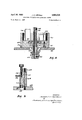
- Fig. 1 is a view in perspective of the printing apparatus of my invention
- Fig. 2 is a plan view thereof
- Fig. 3 is a view in front elevation thereof
- Fig. 4 is a view in cross section of the inkwell and pump mechanism
- Fig. 5 is a view in cross section of the ink riser and needle valve arrangement
- Fig. 6 is a plan view of the wiper arrangement
- Fig. 7 is a plan view in side elevation of the wiper arrangement
- Fig. 8 is a plan view of the cap element for the pump.
- Fig. 9 is a view in cross section in side elevation along the line 9-9 of Fig. 8.
- the preferred embodiment of my invention herein shown comprises a pair of printing elements indicated at 10 and 12 respectively mounted on a base 14 to pivot in a horizontal plane.
- the printing elements 10 and 12 cooperate to print indicia on a wire 15 which is drawn between them.
- the printing elements 10 and 12 will first be described in detail, and thereafter the general cooperative relationship between them will be explained. However, since the printing elements 10 and 12 are completely complementary in their construction, only element 10 will be described herein.
- the basic member for pivotally mounting the printing element 10 is a pivot bearing 16 which serves to support a base plate 20 on which the other elements of the printer are mounted. These other elements include a drive motor 22 and inkwell 24, an ink supply riser 26, a wiper holder 28, a printer disc mounting 30, and a printing disc. 32. a i
- V v V Centrally within the inkwell 24 Iprovide an impeller type pump having vanes38 mounted for, rotation upon a vertical shaft 40. Encasing the vanes 38 is a pump cap member 42 (see Figs. 4, 8 and 9) which defines an opening '44 centrally within the lower portion of the inkwell 24. The opening 44 is provided with an upper entrance 46, through which ink flows downwardly to the impeller blades asjis indicated at 48 in Fig.4.
- the ink is forced outwardly by centrifugal force and into a riser outlet'50 at the side of the opening 44.
- the bottom of the inkwell 24 in the area of the pump shaft 40 is sealed by means of a nylon bearing member 52 which rotates in a bushing member 54 which is, in turn, threaded to the bottom of the inkwell 24.
- the nylon bearing member 52 extends upwardly along the shaft 40 I and serves in part to support a cylindrical sleevemember'56 on which the vanes 38 are mounted.
- the sleeve member 56 is rigidly secured to the shaft 40 by means of'a set screw 58.
- the lower end of the bushing 54' extends downwardly through an opening 60 in the base plate 20, and serves as a bearing member for a sheave 62 which is connected to the lower end of the shaft 40 by means of a set screw 64.
- the nylon bearing'member SZ prevents ink from leaking downwardly adjacent to the shaft 40 in thearea of the inkwell 24 and keeps the upper portion of the shaft 40 in alignment, while the lower portion of the bushing 54 maintains thelowerend of the shaft 40 in vertical alignment by providing a bear: ing surface for the sheave 62.
- the sheave 62 serves to rotate the shaft 40 by means of a belt member 66 which is driven by the motor 22. I n
- Fig. 5 it will be seen that as the rises through the ink outlet 50, it passes into a main body portion 68 of the ink riser 26.
- the body portion 68 is mounted on the cap member 42 by meansof a rod 70 which is screwed into cap member 42 atitslower end and which is held in place at its upper end bymeans of a lock nut 72.
- the ink comes up into the riser 26, it passes from the outlet 50 into a vertical conduit 74 and thereafter through a .needlevalve 76 and out a spigot :78.
- the wiper 28 comprises a vertical body portion 80 connected to the pump cap member 42 by, means of machine screws 82.
- a pivot pin 84 is mounted. in the upper part of the body 80 and serves to position a wiper support 86 adjacent to the disc 32.
- the wiper support is provided with two forwardly extending arms 88 which flank the disc 32 and retain between them a plastic wip- 7 ing blade 90.
- the blade 90 presents a relatively sharp edge pointing against the rotation of the disc 32. In this way the blade 90 serves to scoop off excess ink and re-. turn it to the inkwell with a minimum of disturbance or splatter.
- the wiper support 86 is urged toward the disc 32-by a leaf spring 92, the pressureof which is regulated by an adjusting screw 94 mounted in an upstanding lug 96 on the upper surface of the body portion 80.
- the blade 90 may preferably be made of polyethylene, nylon, polyvinyl alcohol or the like material having good wear characteristics butyet being capable of some dis-1 4 tortion to accommodate slight changes in contour of the edge of the disc.
- the disc 32 rotates in unison therewith continously printing indicia thereon.
- the ink is supplied to the edge of the disc 32 through the spout 78 and the wiper blade 90 immediately scoops off the excess ink which is returned to the inkwell 24.
- the pumping is accomplished by the motor 22 which drives sheave 62 simultaneously rotating shaft 40, sleeve 56 and blades 38.
- the blades 38 drive the ink outwardly andup the riser conduit 74 through the needle valve 76 and out the spout 78.
- the pressure of the wiper bla'deq90 against the disc 32 is regulated by set screw 94 and leaf spring 92.
- I provide a printing element 12 adjacent to the above-described element 10 and with the printing discs of each in opposed relation.
- a tension spring 98 is connected across the front between the two printing elementsand serves to urge the two printing discs against the wire.
- the tension of the spring 98 may be regulated by threaded spring connectors 100.
- I provide a pair of mated gear segments 102, one mounted on each printing element with its pitch circle arranged concentrically to the axis of the pivot support 16 of each printing element.
- a slotted stop screw 104 is also connected across between the printing elements, and serves the purpose of limiting their pivotal motion so that the two printing discs will not quite touch when the wire is not between them.
- discs 32 are shown with complementarily formed grooves in their printing surfaces. This form of disc may be employed to print spiral marking on the wire.
- Apparatus for high speed intaglio printing comprising in combination, a printing disc, means for continuously rolling a side edge of said disc in contact with and against a side surface of an elongated body while moving said body longitudinally, indicia markings on said side edge, a multiplicity of minute serrations in the surface of said side edge of said disc and confined to the area occupied by said indicia markings, means including a spout for continuously applying ink to said side edge under a positive fluid pressure arranged to cause said ink to flow in a direct and continuous path through said spout and onto said side edge without localized accumulation, wiper mechanism for removing excess ink from said side edge in areas apart from said indicia including a blade in sequence closely following said ink applying means, resilient means for urging said blade toward said side edge, said ink applying means and said wiper blade following said ink applying means in the direction of rotation of said printing disc, an ink pot having an upper opening, said upper opening in position below said wiper blade and
- the apparatus defined in claim 1 further characterized by pivotally mounting the entire combination so defined on a base, pivotally mounting a second combination so defined on the same base with the printing disc of the second said combination arranged to press against said elongated body at a point opposite to the point at which the printing disc of said first combination presses thereagainst, and resilient means for urging both said printing discs into pressure contact with said elongated body.
Landscapes
- Inking, Control Or Cleaning Of Printing Machines (AREA)
Description
April 26, 1960 J. c. GEMELLI' PRINTING APPARATUS FOR ELONGATED BODIES Filed March 14, 1957 5 Sheets-Sheet 1 INVENTOR.
\JZSEPl/GZ Q MELL/ April 26, 1960 J. c. GEMELLI PRINTING APPARATUS FOR ELONGATEJD BODIES Filed March 14. 1957 5 Sheets-Sheet 2 INVENTOR. @sep/ 6. CiE/l IELL/ BY peers-e, cfl/rr/ckefieussez4 arrys- April 26, 1960 J. c. GEMELLI 2,934,005
PRINTING APPARATUS FOR ELONGATED BODIES Filed March 14, 1957 6 Sheets-Sheet 3 INVENTOR. Jszpl/c (#MEAL/ paerae' C/// 7'7/CK%'EU55ELL.
grrrs.
J. C. GEMELLI PRINTING APPARATUS FOR ELONGATED BODIES Filed March 14, 1957 April 26, 1960 5 Sheets-Sheet 4 A. .4 1. 2 i 4 M 67 4 p a w? w? 2 a 2 F c a y W a p 7 2 M x W. m M Z 0 E w ill a 6 6 m a i M 8 M a w. J fzz l Lmr 5 6 a 2 i 5 E 45 April 26, 1960 J. c. GEMELLI 2,934,005
PRINTING APPARATUS FOR ELONGATED BODIES Filed March 14, 1957 5 Sheets-Sheet 5 48 46 INVENTOR.
11 5'. .9 arrys- United States Patent PRINTING APPARATUS FOR ELONGATED BODIES Joseph C. Gemelli, Norwell, Mass.
Application March 14, 1957, Serial No. 646,134
3 Claims. (Cl. 101-37) This invention relates to apparatus for printing indicia on continuous bodies and more particularly to intaglio printing on insulated wire and the like.
Hitherto intaglio printing on insulated wire and the like has been accomplished by means of a printing wheel mounted in a vertical plane to rotate with its lower portion immersed in an ink bath and its upper portion in contact with the wire. In this way, as the wire is drawn forward, the wheel rotates in contact with the wire and deposits the ink on it while continuously returning to the bath for more link. This type of conventional apparatus has a number of serious drawbacks. In the first place, at speeds of about 700 ft./min. and greater, despite shields and doctor blades, the wheel commences to spray the ink over the wire and elsewhere, resulting in loss of ink and poor quality wire. Secondly, if the wire is issuing from an insulation extruder in a relatively hot condition, the printing wheel becomes hot and since it also rotates'in the ink bath, it has the eifect of heating the ink. This in turn evaporates the solvent in the ink, rendering it too thick for proper printing. In addition, when the insulation is still hot immediately after extrusion, it is so soft that the printing wheel tends to distort it if sufiicient pressure is applied to print adequately. On the other hand, if the conventional printer is employed at the far end of the water cooling tank, a third disadvantage arises. Under these conditions, the wire brings with it small droplets of water which adhere to the printing wheel or simply drop into the ink. Since the ink employed is heavier than water, the water remains on the surface of the ink, and consequently interferes with the printing. These disadvantages present a serious problem because when high speed extruders are employed, the wire cannot be printed along with extrusion, but must be stored and printed at slower speeds, thus requiring a second operation.
It is, therefore, an object of this invention to provide apparatus for printing insulated wire and the like at high speeds. Another object is to provide apparatus which can print insulated wire and the like at the same speeds as are employed in high speed extruders and following the water cooling apparatus. Another object is to provide such a printing apparatus in which the ink will not spray, despite high speed operation, and in which water droplets do not interfere with the printing operation.
In the accomplishment of these and other objects of my invention in a preferred embodiment thereof, I employ a pair of printing discs mounted to rotate in a horizontal plane with their edges in opposed relation. The wire to be printed is drawn between the two discs with the opposed edges thereof abutting the wire and pressing against it from both sides. The surfaces of one or both of the discs may be provided with indicia markings for intaglio printing, and as the wire is drawn forward, the discs rotate and print on the wire. Ink is supplied to the surface of the discs by means of a rotary impeller type pump which forces the ink upwardly through a small spout and against the surface of the disc. In order to wipe away excess ink, I-provide a wiper blade in contact with the edge of the disc adjacent to the spout. The wiper is positioned directly above the inkwell, and excess ink simply drops down into the inkwell. In this way, the only ink remaining on the disc is the ink that is lodged in the indicia for printing. Accordingly, the disc may rotate at very high speeds without spraying the ink around on the work piece.
It is a feature of my invention that the disc does not rotate in the inkwell. Thus, there is no tendency to draw up excess ink and spray it around during high speed printing.
A further feature of my invention is that the ink supply is drawn from the bottom of the inkwell. This means that water may drop down into the inkwell, and, being lighter than the ink, no harm results therefrom. The importance of this feature is that the printing may be carried out on extruded wire in series following the cooler.
Still another feature of my invention is that the disc may become heated without substantially raising the temperature of the ink. This means that the volatiles in the ink are not overly evaporated, and the viscosity of the ink tends to remain more stable and in better condition for printing.
Other important features of my invention include: (a) pointing the ink spout directly against the surface of the edge of the disc to ensure application of ink thereon under an appreciable degree of fluid pressure; ([7) wiping the excess ink oif the disc by means of a relatively sharp blade pointed in a direction opposite to the disc rotation; and (0) providing the intaglio indicia surfaces with a network of microscopic serrations to increase the surface tension for the ink therein in order to resist the centrifugal forces of the disc rotation.
Further objects and features of this invention will best be understood and appreciated from the detailed description of a preferred embodiment thereof, selected for purposes of illustration, and shown in the accompanying drawings, in which:
Fig. 1 is a view in perspective of the printing apparatus of my invention;
Fig. 2 is a plan view thereof;
Fig. 3 is a view in front elevation thereof;
Fig. 4 is a view in cross section of the inkwell and pump mechanism;
Fig. 5 is a view in cross section of the ink riser and needle valve arrangement;
Fig. 6 is a plan view of the wiper arrangement;
Fig. 7 is a plan view in side elevation of the wiper arrangement;
Fig. 8 is a plan view of the cap element for the pump; and
Fig. 9 is a view in cross section in side elevation along the line 9-9 of Fig. 8.
The preferred embodiment of my invention herein shown comprises a pair of printing elements indicated at 10 and 12 respectively mounted on a base 14 to pivot in a horizontal plane. The printing elements 10 and 12 cooperate to print indicia on a wire 15 which is drawn between them. In this description, the printing elements 10 and 12 will first be described in detail, and thereafter the general cooperative relationship between them will be explained. However, since the printing elements 10 and 12 are completely complementary in their construction, only element 10 will be described herein.
The basic member for pivotally mounting the printing element 10 is a pivot bearing 16 which serves to support a base plate 20 on which the other elements of the printer are mounted. These other elements include a drive motor 22 and inkwell 24, an ink supply riser 26, a wiper holder 28, a printer disc mounting 30, and a printing disc. 32. a i
formed as a shallow cylindrical member secured to the base plate 20 by means of a plurality of flange-headed 7 screws 34 and a set screw 36 fitting into a groove 37 Iwhich'ruris around the base of the inkwell 24 on the out: side (seeFigs. 1(2 and 3). V v V Centrally within the inkwell 24 Iprovide an impeller type pump having vanes38 mounted for, rotation upon a vertical shaft 40. Encasing the vanes 38 is a pump cap member 42 (see Figs. 4, 8 and 9) which defines an opening '44 centrally within the lower portion of the inkwell 24. The opening 44 is provided with an upper entrance 46, through which ink flows downwardly to the impeller blades asjis indicated at 48 in Fig.4. Thus, when the shaft 4% is rotated carrying the vanes 38 around in .rotation, the ink is forced outwardly by centrifugal force and into a riser outlet'50 at the side of the opening 44. .The bottom of the inkwell 24 in the area of the pump shaft 40 is sealed by means of a nylon bearing member 52 which rotates in a bushing member 54 which is, in turn, threaded to the bottom of the inkwell 24. The nylon bearing member 52 extends upwardly along the shaft 40 I and serves in part to support a cylindrical sleevemember'56 on which the vanes 38 are mounted. The sleeve member 56 is rigidly secured to the shaft 40 by means of'a set screw 58. The lower end of the bushing 54' extends downwardly through an opening 60 in the base plate 20, and serves as a bearing member for a sheave 62 which is connected to the lower end of the shaft 40 by means of a set screw 64. In this way, the nylon bearing'member SZ prevents ink from leaking downwardly adjacent to the shaft 40 in thearea of the inkwell 24 and keeps the upper portion of the shaft 40 in alignment, while the lower portion of the bushing 54 maintains thelowerend of the shaft 40 in vertical alignment by providing a bear: ing surface for the sheave 62. The sheave 62 serves to rotate the shaft 40 by means of a belt member 66 which is driven by the motor 22. I n
Turning now to Fig. 5, it will be seen that as the rises through the ink outlet 50, it passes into a main body portion 68 of the ink riser 26. The body portion 68 is mounted on the cap member 42 by meansof a rod 70 which is screwed into cap member 42 atitslower end and which is held in place at its upper end bymeans of a lock nut 72. As the ink comes up into the riser 26, it passes from the outlet 50 into a vertical conduit 74 and thereafter through a .needlevalve 76 and out a spigot :78. The
delivery end of the spigot 78 is positioned close to and pointing directly toward the edge of the disc 32.- 'Inthis and 7'). The wiper 28 comprises a vertical body portion 80 connected to the pump cap member 42 by, means of machine screws 82. A pivot pin 84 is mounted. in the upper part of the body 80 and serves to position a wiper support 86 adjacent to the disc 32.- The wiper support is provided with two forwardly extending arms 88 which flank the disc 32 and retain between them a plastic wip- 7 ing blade 90. The blade 90 presents a relatively sharp edge pointing against the rotation of the disc 32. In this way the blade 90 serves to scoop off excess ink and re-. turn it to the inkwell with a minimum of disturbance or splatter.
In order to maintain a uniform and proper pressure between the wiper blade 90 and the edge of the disc 32, the wiper support 86 is urged toward the disc 32-by a leaf spring 92, the pressureof which is regulated by an adjusting screw 94 mounted in an upstanding lug 96 on the upper surface of the body portion 80.
The blade 90 may preferably be made of polyethylene, nylon, polyvinyl alcohol or the like material having good wear characteristics butyet being capable of some dis-1 4 tortion to accommodate slight changes in contour of the edge of the disc.
It will now be seen that as the wire 15 is drawn forwardly, the disc 32 rotates in unison therewith continously printing indicia thereon. The ink is supplied to the edge of the disc 32 through the spout 78 and the wiper blade 90 immediately scoops off the excess ink which is returned to the inkwell 24. The pumping is accomplished by the motor 22 which drives sheave 62 simultaneously rotating shaft 40, sleeve 56 and blades 38. The blades 38 drive the ink outwardly andup the riser conduit 74 through the needle valve 76 and out the spout 78. The pressure of the wiper bla'deq90 against the disc 32 is regulated by set screw 94 and leaf spring 92.
With this arrangement it is, of course, possible to print only one side of the wire with an idler wheel supporting the other side. However, the usual application calls for printing on both sides. Accordingly in the embodiment hereinshown, I provide a printing element 12 adjacent to the above-described element 10 and with the printing discs of each in opposed relation. A tension spring 98 is connected across the front between the two printing elementsand serves to urge the two printing discs against the wire. The tension of the spring 98 may be regulated by threaded spring connectors 100.
In order to maintain the printing elements 10 and .12 in proper alignment and to assure uniform printing pressure on both sides of the wire 15, I provide a pair of mated gear segments 102, one mounted on each printing element with its pitch circle arranged concentrically to the axis of the pivot support 16 of each printing element.
A slotted stop screw 104 is also connected across between the printing elements, and serves the purpose of limiting their pivotal motion so that the two printing discs will not quite touch when the wire is not between them.
While I have shown motor 22 driving the ink pump independently of the rotation of the disc32, it will be understood that I may also employ the rotation of the disc 32 to drive the pump. This is done by placing the belt 66 on a sheave 106 which is connected to the lower extremity of a shaft 108 on which the disc 32 is mounted for rotation. In this way turning the disc 32 willalso turn sheave 62 and .drive the ink pump. n With such .an arrangement, I find that printing at all but very slow speeds is entirely satisfactory. a The surface of the intaglio indicia employed inmy invention is also important. I'have found that conventional indicia do not hold the ink under high speed dynamic conditions. .In my invention, I accomplish this by forming the letters by means of a combination of line and halftone iphotogravured intaglio. The line image ensures sharp edges for the indicia and the half-tone screen is employed to' provide an uneven surface within the area of the indicia proper. I employ a l20 mesh screen and the result isto leave a multiplicity of microscopic serrations in the surface of the indicia itself. I
at least 3000 ft./min. without loss of definition in the printed characters. This means that it can easily handle the output of high speed extruders in direct series therewith. In addition, since the ink comes up from the bottom of the inkwell 24 to the spout 78, water droplets do not interfere with the printing. In this connection it will also be seen that applying the ink to the disc edge under conditions of fluid pressure also serves to dispel the water droplets from the area of the indicia.
'In Figs. 1 and 3 it will be seen that the discs 32 are shown with complementarily formed grooves in their printing surfaces. This form of disc may be employed to print spiral marking on the wire.
Since numerous minor variations of this preferred embodiment'of my invention will now be apparent to those Having thus described and disclosed a preferred embodiment of my invention, what I claim as new and desire to secure by Letters Patent of the United States is:
1. Apparatus for high speed intaglio printing comprising in combination, a printing disc, means for continuously rolling a side edge of said disc in contact with and against a side surface of an elongated body while moving said body longitudinally, indicia markings on said side edge, a multiplicity of minute serrations in the surface of said side edge of said disc and confined to the area occupied by said indicia markings, means including a spout for continuously applying ink to said side edge under a positive fluid pressure arranged to cause said ink to flow in a direct and continuous path through said spout and onto said side edge without localized accumulation, wiper mechanism for removing excess ink from said side edge in areas apart from said indicia including a blade in sequence closely following said ink applying means, resilient means for urging said blade toward said side edge, said ink applying means and said wiper blade following said ink applying means in the direction of rotation of said printing disc, an ink pot having an upper opening, said upper opening in position below said wiper blade and adapted to receive ink by gravity flow wiped from said side edge by said blade, and pumping means for pumping 6 ink substantially through the surface of said ink in said ink pot to said ink applying means.
2. The apparatus defined in claim 1 further characterized by said blade being composed of a resilient and yield able plastic material.
3. The apparatus defined in claim 1 further characterized by pivotally mounting the entire combination so defined on a base, pivotally mounting a second combination so defined on the same base with the printing disc of the second said combination arranged to press against said elongated body at a point opposite to the point at which the printing disc of said first combination presses thereagainst, and resilient means for urging both said printing discs into pressure contact with said elongated body.
References Cited in the file of'this patent UNITED STATES PATENTS 1,262,707 Smith Apr. 16, 1918 2,014,303 Weiss Sept. 10, 1935 2,210,923 Jacquerod et al. Aug. 13, 1940 2,638,843 Halley May 19, 1953 2,704,026 Rogge et al Mar. 15, 1955 FOREIGN PATENTS 152,876 Australia Aug. 18, 1953
Priority Applications (1)
| Application Number | Priority Date | Filing Date | Title |
|---|---|---|---|
| US646134A US2934005A (en) | 1957-03-14 | 1957-03-14 | Printing apparatus for elongated bodies |
Applications Claiming Priority (1)
| Application Number | Priority Date | Filing Date | Title |
|---|---|---|---|
| US646134A US2934005A (en) | 1957-03-14 | 1957-03-14 | Printing apparatus for elongated bodies |
Publications (1)
| Publication Number | Publication Date |
|---|---|
| US2934005A true US2934005A (en) | 1960-04-26 |
Family
ID=24591903
Family Applications (1)
| Application Number | Title | Priority Date | Filing Date |
|---|---|---|---|
| US646134A Expired - Lifetime US2934005A (en) | 1957-03-14 | 1957-03-14 | Printing apparatus for elongated bodies |
Country Status (1)
| Country | Link |
|---|---|
| US (1) | US2934005A (en) |
Cited By (6)
| Publication number | Priority date | Publication date | Assignee | Title |
|---|---|---|---|---|
| US3739717A (en) * | 1971-07-02 | 1973-06-19 | Riggs & Lombard Inc | Wire printing apparatus having closed inking system |
| FR2302856A2 (en) * | 1975-03-01 | 1976-10-01 | Int Standard Electric Corp | RELIEF MARKING DEVICES FOR PLASTIC CABLES |
| US4077317A (en) * | 1974-11-04 | 1978-03-07 | Siemens Aktiengesellschaft | Apparatus for imprinting an elongated member |
| US4299163A (en) * | 1979-06-12 | 1981-11-10 | Formulabs Industrial Inks, Incorporated | High speed conductor coding apparatus |
| US4911072A (en) * | 1988-05-02 | 1990-03-27 | Southwire Company | Side wiper for high speed cable printer |
| US5440982A (en) * | 1993-07-01 | 1995-08-15 | Meadows; Stanley J. | Inking system for a printing press |
Citations (5)
| Publication number | Priority date | Publication date | Assignee | Title |
|---|---|---|---|---|
| US1262707A (en) * | 1916-06-19 | 1918-04-16 | Goss Printing Press Co Ltd | Inking mechanism. |
| US2014303A (en) * | 1933-07-22 | 1935-09-10 | Weiss Adolph | Rotary intaglio printing |
| US2210923A (en) * | 1939-07-10 | 1940-08-13 | Jacquerod | Process of graining intaglio and gravure printing plates |
| US2638843A (en) * | 1950-05-08 | 1953-05-19 | Halley Angus Murray | Rotary photogravure printing machine |
| US2704026A (en) * | 1953-08-24 | 1955-03-15 | Edmund A Rogge | Doctor blade and mounting for rotogravure printing machines |
-
1957
- 1957-03-14 US US646134A patent/US2934005A/en not_active Expired - Lifetime
Patent Citations (5)
| Publication number | Priority date | Publication date | Assignee | Title |
|---|---|---|---|---|
| US1262707A (en) * | 1916-06-19 | 1918-04-16 | Goss Printing Press Co Ltd | Inking mechanism. |
| US2014303A (en) * | 1933-07-22 | 1935-09-10 | Weiss Adolph | Rotary intaglio printing |
| US2210923A (en) * | 1939-07-10 | 1940-08-13 | Jacquerod | Process of graining intaglio and gravure printing plates |
| US2638843A (en) * | 1950-05-08 | 1953-05-19 | Halley Angus Murray | Rotary photogravure printing machine |
| US2704026A (en) * | 1953-08-24 | 1955-03-15 | Edmund A Rogge | Doctor blade and mounting for rotogravure printing machines |
Cited By (6)
| Publication number | Priority date | Publication date | Assignee | Title |
|---|---|---|---|---|
| US3739717A (en) * | 1971-07-02 | 1973-06-19 | Riggs & Lombard Inc | Wire printing apparatus having closed inking system |
| US4077317A (en) * | 1974-11-04 | 1978-03-07 | Siemens Aktiengesellschaft | Apparatus for imprinting an elongated member |
| FR2302856A2 (en) * | 1975-03-01 | 1976-10-01 | Int Standard Electric Corp | RELIEF MARKING DEVICES FOR PLASTIC CABLES |
| US4299163A (en) * | 1979-06-12 | 1981-11-10 | Formulabs Industrial Inks, Incorporated | High speed conductor coding apparatus |
| US4911072A (en) * | 1988-05-02 | 1990-03-27 | Southwire Company | Side wiper for high speed cable printer |
| US5440982A (en) * | 1993-07-01 | 1995-08-15 | Meadows; Stanley J. | Inking system for a printing press |
Similar Documents
| Publication | Publication Date | Title |
|---|---|---|
| US4060031A (en) | Printing method and apparatus for performing the printing method | |
| US2363817A (en) | Printing process and mechanism | |
| US3739717A (en) | Wire printing apparatus having closed inking system | |
| US4432282A (en) | Printing press | |
| JPH04219251A (en) | Wiper for ink jet print head | |
| US2293690A (en) | Process of coating web material | |
| US2931297A (en) | Ink seal means for rotary intaglio printing mechanism | |
| KR960003335B1 (en) | Inking arrangement | |
| US4077317A (en) | Apparatus for imprinting an elongated member | |
| US2417009A (en) | Process of coating with thermoplastic material | |
| US3828665A (en) | Marking apparatus for elongated objects | |
| US2106029A (en) | Inking mechanism and method for printing machines | |
| CS231162B2 (en) | Device for making of thin layer from liquid | |
| US1807991A (en) | Graining machine | |
| US3417693A (en) | Device for reducing turbulence in printing press fountains | |
| US2178070A (en) | Inking mechanism | |
| US2905087A (en) | Printing mechanism | |
| US3645202A (en) | Lithographic inking dampening system | |
| US2112459A (en) | Ink fountain construction for use in printing presses | |
| US4287828A (en) | Ink metering apparatus | |
| US2278387A (en) | Method and apparatus for inking printing cylinders | |
| US4796549A (en) | Ink supplying apparatus | |
| JPH0616043U (en) | Ink supply device for printing machine | |
| US2150174A (en) | Apparatus for sectioning of inking rollers | |
| US2267892A (en) | Inking apparatus for rotary intaglio printing presses |