US2954884A - Flexible gas seal for a blast furnace - Google Patents
Flexible gas seal for a blast furnace Download PDFInfo
- Publication number
- US2954884A US2954884A US779894A US77989458A US2954884A US 2954884 A US2954884 A US 2954884A US 779894 A US779894 A US 779894A US 77989458 A US77989458 A US 77989458A US 2954884 A US2954884 A US 2954884A
- Authority
- US
- United States
- Prior art keywords
- ring
- hopper
- seal
- blast furnace
- face
- Prior art date
- Legal status (The legal status is an assumption and is not a legal conclusion. Google has not performed a legal analysis and makes no representation as to the accuracy of the status listed.)
- Expired - Lifetime
Links
Images

Classifications
-
- C—CHEMISTRY; METALLURGY
- C21—METALLURGY OF IRON
- C21B—MANUFACTURE OF IRON OR STEEL
- C21B7/00—Blast furnaces
- C21B7/18—Bell-and-hopper arrangements
Definitions
- a spring encircles the flexible lip portion of the seal and fits in the space defined by the supporting portion ⁇ andthe ilexible lip portion. This spring pushes the lip portion radially inwardly against the cylindrical outer surface of the hopper to provide the gas tight seal.
- y1960 2 urge the iiexible lip into tighter engagement with the bell hopper.
- an object of the presen-t invention to provide an improved gas seal for the revolving distributor ofa blast furnace which utilizes a pair of rigid fixed rings which encircle the bell hopper and define an annular ⁇ space with a beveled inner upper wall in conjunction with a fixed seal ring having an outer portion that ii-ts snugly again-st the outer portions of the space so defined, has a support portion extending radially inwardly along the top roof of the space, and has a ilexible inner lip that is received against the beveled inner upper Wall and projects radially inwardly therefrom to wipe against the outer cylindrical face of the revolving distributor to define the seal.
- Figure l is an axial cross-section View with parts in elevation of a small bell hopper assembly and revolving distributor employing a gas seal made in accordance with the present invention
- Figure-2 is an enlarged fragmentary view similar to Figure l showing an alternative construction of the mechanism of Figure l;
- Figure 3 is an enlarged cross-sectional view of the flexible gas seal and adjacent portions of the structure of Figure l.
- FIG. 1 a flexible gas seal for the revolving distributor of a blast furnace
- the ilexible gas seal 10 includes three elements, namely, segmented support seal ring 12, segmented cap ring 14 and t sealing ring 16, all of which will be discussed in more pressure created from fthe Vhot blast gas also serves to f detail hereinafter.
- the seal 10 is located near the juncture of rotating bell hopper 18 and blast furnace 20 to prevent the escape of blast furnace gas generated in the furnace.
- Hopper 18 is rotated by electric motor 24.
- Shaft 25 of motor 24 has a pinion 28 which meshes with ring gear 30.
- ring gear 311 is aflixed to flange 18a of hopper 18 bymeans of bolt 30a.
- the ning ⁇ A'1 8 and secures that shell to ring gear 30.
- Flanges 34 are located between theouter jacket 32 andthe main inner cylinder 36 of the hopper.
- the hopper portion 36 is made in the form Vof circular segments, preferably quadrants, secured together by the bolts 34a received in yfianges 3d.
- the outer cylindrical jacket 32 extends below gear 30
- the bolt 3fm also has a downwardly extending beveled roof 13 at its inner edge.
- the cap ring 14 additionally defines an upper annular chamber 17, Figure 3.
- The'lower part of this chamber is defined by the portion 14d of the ring 14 which is downwardly beveled and terminates in the cylindrical face 14e closely adjacentthe ⁇ jacket 32.
- the top part of the upper chamber 17 Yis defined by the overhanging portion' 14a'of the cap ring 14 and the portion 32hV of the jackety 32 which seats beneath this overhanging portion.
- the 'lower annular chamber 1S receives the flexible seal ring 16. As shown, this ring at'its outer periphery is received snugly vin the outer portion of the chamber 15, which in this region is of rectangular cross-section as shown in Figure 3. v'The seal ringV 16 at its upper p0rtion extends inwardly Vin an overhanging portion 15b which seats against the roof 141 and terminates in the sloping downwardly extending yskirt 16C. . The latter at and terminates at the seal ring 12. KVAs shown, ring 3i) is stationary and is affixed to the top of the furnace. The
- the outer cylinder 3-2 has a. pair of circumferential outwardly extending ribs which are received in corresponding recesses 12a .in seal ring 12.
- the outer cylindrical sleeve 32 also has an upper outwardly extending rib 32h which is of generally rectangular cross-section andv has an annular upwardly facing groove 32e, Figure 3.
- the inwardly extending top ange 14a of the cap 14 overhangs rib 32th, as shown, and has a depending skirt 1411 that extends into the groove 32C as shown.
- the brackets 13, Figure l each receive an angle bar unit 15 having a horizontal part 15b, a radial vertical gusset plate 15a, and a verticalrouter support plate 15e.
- the latter carries the trunnions 17a and 17h which sup'- po-rt the guide rollers 19 of their vertical axes and in engagement with the outer cylindrical faces straddling th gear teeth of gear 3).
- the small kbell hopper 136 defines the circumferential flanges or ridges 136a,.as shown. that of Figures l and S-is received over these ridges as shown, with the mating circumferential slots 12a of the seal ring each receiving one of the ridges 136m
- the bell hopper 1367 has no annular ridge corresponding to ridge 3211, Figures lV and 3, although such ridge may be provided, if desired.
- the annular cap 114 which seats on Ithe seal 12 as shown has a simple inwardly Vfacing ⁇ circumferential groove 114g, into which a conventionalf The seal ring 12--of the same construction as f packing (not shown) may be inserted if desired.
- Thering 113 is sandwiched between the rings 112 and 114 to define the cavity into which the flexible seal ring 1 is disposed as hereinafter described. indetail.
- The4 rigid stationary seal ring 12 has an annular recess at its upper inner edge, defining the annular horizontal surface 42. and the cylindrical vertical surface 44.
- the fixed vcap ring 14 has an annular horizontal portion 143 that overlays this recess and at its inner edge terminates in a1- beveled downwardly conical face 13.V
- the conical'face 13 is defined by a depending shirt terminating at the inner' cylindrical face 14e which -is slightly spaced from the cylindrical jacket 32. It will be noted that by this'com struction,fthere is defined an annularachamber 15 about' the jacket 32 which faces thercylindnical face of the jacket lubricant under modest pressure.
- lskirt ⁇ 16c has a toroidal shoulder 16d on its lower outer Vportion which receives the spiral spring 21.
- The-latter Vhoop tension and urges the unsupported extending portion ofthe ring 16 inwardly against the face-of the jacket 32 to define an effective seal.
- the seal ring 12 has a shallow annular 'recess 43 which serves to provide an adequate clearance between the Ylowermost margin of the skirt 16e of the ring 16 and the lower faceof the chamber 15. This assures that the blast furnace gasY pressure in the cylindrical clearance space 33 between jacket 32 and seal ring 12 is effective in the chamber 15.
- This gas pressure serves to reinforce the action of the spring 21 in urging lthe skirt 16C snugly against the cylindrical outer face of jacket 32. This is due to the unbalanced pressure against the inside face of the depending or skirt portion of the seal 16 which, it will be noted, tends to flex the ring 16 inthe samemanner as the spring 21.
- the chamber 17 is preferably filled with grease or Suitable pressure 1ubricant fittings (not shown) are provided at openings 17a (which are distributed aboutY the periphery of the ring The pressure in this chamber, however, is definitely less than that in the clearance space 33.
- yThecap vring 114 of Figure 2 is likewise formed on its lower inner face to dene a fiat annular roof and a depending inner skirt in the same fashion as ⁇ the top cap 1 4y of Figure 3.
- annular chamber 15 is defined in the structure of Figure 2 with the same shape as the chamber 15, Figure 3.
- the seal ring 16 is like ring 16, Figure 3, and is placed in chamber 15, Figure 2, and operates in the same fashion as the ring 16 of Figure 3.
- the seal ring 16 Since the seal ring 16 is in-'thermal contact'with the *upper part of the blast furnace, it must withstand the heatrof ⁇ that portion of the blast furnace. Moreover, the seal ring 16 is in-'thermal contact'with the *upper part of the blast furnace, it must withstand the heatrof ⁇ that portion of the blast furnace. Moreover, the seal ring 16 is in-'thermal contact'with the *upper part of the blast furnace, it must withstand the heatrof ⁇ that portion of the blast furnace. Moreover, the
- the spring 21 is preferably of stainless steel to assure that it will elfectively withstand the elevated temperatures and corrosive atmosphere to which it is exposed.
- the revolving distributor seal ofthe present invention is assembled by independently supporting the bell hopper in desired position (e.g. by'suspending the same by block and tackle). A t this time, or previously, the flexible seal ring 16 is placed around the cylindrical surface it encompasses-(32, Figure 1 and3, 136, Figure 2). V'Ihe spring 21 is then wrapped about the portion 16e of the ring and seated in the groove 16d. The segments forming the seal vring 12 are now placed in-po'sition and anchored by the bolts 38. ⁇ At this time the seal ring 16 is pushed down into the annular chamber 15, which is open at its top since the cap ring 14 is not yet in position. VThe'segments of the cap ring 14,are now placed in position and secured in proper location by the bolts 40, Figure 3, to complete the assembly.V
- the small bell hopper is givenl successive rotations in a predetermined program to distribute the load uniformly.
- the apparatus of the present invention has been found to require less driving power than the prior units. AThis not only reduces the requiredk motor size, but in addition indicates that AVless wear is taking place with the incident prospect ofY greater life. A
- a flexible gas seal construction for the revolving distributor of a blast furnace having a rotating bell hopper defining an outer cylindrical face comprising in combination: a fixed support ring affixed to the blast furnace in the region of the juncture of the blast furnace and the bell hopper and extending around said hopper; a segmented ring mounted on said support ring and extending around said hopper, said rings coacting to define an annular chamber facing the hopper wall and having a generally rectangular cross section with a downwardly beveled inner roof surface; a sealing ring having an outer portion seated snugly in the outer portion of the chamber, an inwardly extending support portion seated against the roof of the chamber and a depending flexible lip portion seated against the beveled inner roof surface and extending inwardly of the same to bear against the hopper; and a spring encircling the flexible lip below the lower margin of the ceiling of said chamber to urge the exible lip against the bell hopper at all times.
- a gas seal construction for the revolving distributor of a blast furnace having a bell hopper which is rotated intermittently to distribute the charge therefrom comprising in combination: a cylindrical outer jacket affixed to and surrounding the bell hopper, the jacket having at least one outwardly extending circumferential rib; a first segmented ring encircling the outer jacket and having a circumferential inner recess in mating relationship with therib of the ⁇ outer jacket, the segmented ring further having an upper inner circumferential recess; a second segmented ring received over and a'ixed to .the rst segmentedl ring, said second segmented.
- a flexible sealing ring received in the chamber ldefined by said rings, said sealing ring fitting snugly in the outer portion of said chamber and having an inwardly extending portion located at the ⁇ roof thereof and extending downwardly and inwardly along the conical face of said second segmented ring and outboard the lower lip thereof to'partially unsupported engagement with the face of the ⁇ cylindrical outer jacket; and aspring encircling the face of the sealing ring in the region below the lower lip of said second segmented ring to Hex the ,same inwardly against the cylindrical jacket surface.
- a gas seal Yconstruction for the revolving distributor of a blast furnacehaving a bell hopper which is rotated intermittentlyV tof distribute Ythe charge therefrom comprising in combination: a cylindrical outer jacket aixed to and surrounding the bell hopper, the jacket having at least one outwardlyextending circumferential rib; a first segmented ring encircling the outer jacket and having a circumferential inner Vrecess in matingV relationship with the rib of the outer jacket, the segmented ringrfurther having anupper inner circumferential recess; a second segmented ring received over and axed to the first segmented ring, said second segmented ring extending inwardly over said recess towards the surface of the jacket and forming Aa downwardly extending lip with an outer downwardlyY conicalface terminating short of the lower edge of .said recess, thus(Y defining an annular chamber in conjunction with the rst segmented ring; a flexible silicone resin ring
- a gas seal construction for the revolving distributor of a blast furnace having a bell hopper defining a cylindrical outer face with at least one outwardly extending circumferential rib which is rotated intermittently to distribute the charge therefrom comprising in combination: a first segmented ring encircling the outer jacket and having a circumferential inner recess in mating relationship with the rib of the bell hopper, the segmented ring further having an upper inner circumferential recess; a second segmented ring received over and a'ixed to the rst segmented ring, said second segmented ring extending inwardly over said recess towards the surface of the jacket and forming a downwardly extending lip with an outer downwardly conical face terminating short of the lower edge of said recess, thus defining an annular chamber in conjunction with the first segmented ring; a flexible sealing ring received in the chamber defined by said rings, said sealing ring fitting snugly in the outer portion of said chamber and having an inward
- a gas seal construction for the revolving distributor of a blast furnace having a bell hopper defining a cylindrical outer face with at least one outwardly extending circumferential rib which is rotated intermittently to distribute the charge therefrom comprising in combination: a first segmented ring encircling the outer jacket and having a circumferential inner recess in mating relationship with the rib of the bell hopper, the segmented ring further having an upper inner circumferential recess; a second segmented ring received over and affixed to the first segmented ring, said second segmented ring extending inwardly over said recess towards the surface of the jacket and forming a downwardly extending lip with an outer downwardly conical face terminating 'short of the lower edge of said recess, thus defining anl annular chamber in conjunction with the first segmented ring; a flexible silicone resin sealing ring received in the chamber defined by said rings, said sealing ring fitting snugly in the outer portion of said chamber and having an
- a sealing unit for the revolving cylindrical dis- -tributer hopper of a blast furnace comprising: a fixed means defining an annular chamber having a floor and a roof and encircling and facingV the cylindrical face of the hopper and in communication at its floor with the interior of the blast furnace, the roof having a downwardly beveled inner portion terminating close to but in spaced relation to the hopper and above the door; an annular exible seal located in said chamber, said seal being snugly received in the chamber at its outer periphery and having.
- a fixedV means defining an annular chamber having a oor and a roof and encircling and facing the cylindrical face of the hopper, and in communicationvat its floor with the interior of the blast furnace, the roof having a downwardly beveled inner portion terminating close to but in spaced relation to therhopper and above the floor; an annular ⁇ ilexibleV silicone resin seal located in said chamber, said seal being snugly yreceived in Athe chamber at its outer periphery and having a depending conical skirt portion ⁇ extending along the'beveled inner portion of the roof of the chamber and inwardlyY thereof to wipe against the face ofthe hopper; and spring means girdling the outer face of said skirt below the lower edge of the roof of the chamber to flex th'e' lip ofthe seal inwardly against the cylindrical distributor surface.
- a sealing unit for the revolving distributor hopper of a blast furnace comprising: means defining a conical support surface adjacent to but spaced from the hopper; an annular flexible silicon resin seal ring having a conical web seated at its inner surface on said support surface and extending ⁇ to'wiping Vcontact with the hopper; and, spring means girdling the seal ring on a circle of the contact located vbetween the lip of the support surface and the line of contact with the hopper to flex the seal ring against the hopper.
Landscapes
- Engineering & Computer Science (AREA)
- Chemical & Material Sciences (AREA)
- Manufacturing & Machinery (AREA)
- Materials Engineering (AREA)
- Metallurgy (AREA)
- Organic Chemistry (AREA)
- Blast Furnaces (AREA)
Description
0st. 4, 1960 w. c. WILKENING 2,954,884
FLEXIBLE: GAS SEAL FOR A BLAST FURNACE Filed D60. l2, 1958 2 Sheets-Sheet l y 2 Sheets-Sheet 2 W. C. WILKENING FLEXIBLE GAS SEAL FOR A BLAST FURNACE Oct.. 4, 1960 v Filed Dee. 12. 195e rzc/er-f Gsmeq/ UniteV States Patenti() FLEXIBLE GAs SEAL Fon A BLAST FURNACE Walter C. Wilkening, Chicago, Ill., assignor to John Mohr & Sons, Chicago, Ill., a corporation of Illinois Filed Dec. 12, 1958, Ser. No. 779,894
"8 Claims. (Cl. 214-36) VVsleeve with a beveled lower margin. A conical bell or valve is normally held upwardly against this hopper and n accordingly holds the charged materials in the hopper. Periodically, the bell is moved downwardly to cause the charging materials to discharge downwardly into the largeV bell hopper. This bell hopper is -similarly closed by a vertically movable conical bell or valve which is normally held in seated position againstthe lower beveled margin of the hopper. In some furnaces athird similarly constructed bell hopper and bell is provided and is likewise intermittently filled with the charging materials and intermittently discharged.
In order to distribute the charge of materials in circumferentially uniform fashion, it is customary to provide at least one bell hopper, preferably the small bell hopper, with means to rotate the same by a predetermined angle between successive actuations.l After successive loads that hopper is rotated bodily in a program of differing angular rotations and at the end ofeach such `rotation the bell is depressed and the load discharged. .Thusthe loads are distributed at spaced points about the yfurnace to provide circumferentially uniform load dis- ;tribution. v "Mln ythis revolving vdistributor construction it is necessary toprovide a gas-tight seal between the revolvable bell hopper and the jacket of the furnace. Otherwise the valuable andr dangerous blast furnace gases will escape and -the whole purpose of the bell hoppers defeated. The
:seal required for this purpose must withstand the adverse conditions of dust, heat, and other conditions incident to nblast furnace operation. It must also have long life and be readily installed and removed.
of" the bell hopper.
section that ts snugly in the radially outward portion of the annular yspace formed by the rings, an inwardly extending-supporting portion which nests against the upper of the rings, and a downwardly and inwardly extending Lexible'lip portion which likewise seats against the upper of the rings and projects radially inwardly therefrom to a seating engagement with the cylindrical wall of the bell hopper. A spring encircles the flexible lip portion of the seal and fits in the space defined by the supporting portion `andthe ilexible lip portion. This spring pushes the lip portion radially inwardly against the cylindrical outer surface of the hopper to provide the gas tight seal. The
' made in accordance with the present invention.
. afented or-4, y1960 2 urge the iiexible lip into tighter engagement with the bell hopper.
It is therefore a general object of the present invention to provide an improved ilexible gas seal for the revolving distributor of a blast furnace.
t It is a further object of the present invention to provide an improved flexible gas seal for the revolving distributor of a blast furnace having a flexible lip portion that iS encircled by a spring to define a tight seal even in the absence of gas pressure.
It is another object of the present invention to provide an improved seal for the revolving distributor of a blast furnace which utilizes a ring having a flexible sealing lip which is urged by the gas pressure to increasedsealing relation with the hopper.
Further it is an object of the presen-t invention to provide an improved gas seal for the revolving distributor ofa blast furnace which utilizes a pair of rigid fixed rings which encircle the bell hopper and define an annular `space with a beveled inner upper wall in conjunction with a fixed seal ring having an outer portion that ii-ts snugly again-st the outer portions of the space so defined, has a support portion extending radially inwardly along the top roof of the space, and has a ilexible inner lip that is received against the beveled inner upper Wall and projects radially inwardly therefrom to wipe against the outer cylindrical face of the revolving distributor to define the seal.
It is still another object of the present invention to provide an improved ilexible gas seal for the revolving distributor of a blast furnace which is inexpensive to manufacture, reliable in operation, simple to install and remove, highly eiiicient in preventing hot blast gas from discharging into the atmosphere and adapted for installation on any type blast furnace. a
The novel features which I believe to be characteristic `of my invention are set forth with particularity in the ap- .pended claims. My invention itself, however, both as fto its organization and method of operation, together with further objects and advantages thereof, will best be understood by reference to the following description taken in conjunction with the accompanying drawings in which:
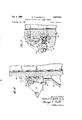
Figure l is an axial cross-section View with parts in elevation of a small bell hopper assembly and revolving distributor employing a gas seal made in accordance with the present invention; n
' Figure-2 is an enlarged fragmentary view similar to Figure l showing an alternative construction of the mechanism of Figure l; and,
Figure 3 is an enlarged cross-sectional view of the flexible gas seal and adjacent portions of the structure of Figure l.
. There is shown generally at 10, Figures 1 3, a flexible gas seal for the revolving distributor of a blast furnace The ilexible gas seal 10 includes three elements, namely, segmented support seal ring 12, segmented cap ring 14 and t sealing ring 16, all of which will be discussed in more pressure created from fthe Vhot blast gas also serves to f detail hereinafter. The seal 10 is located near the juncture of rotating bell hopper 18 and blast furnace 20 to prevent the escape of blast furnace gas generated in the furnace.
uneven manner. The small bell 22 and its hopper 18 are rotated before the small bell 22 is depressed to provide a more even distribution of the charge in the furnace.`
Hopper 18 is rotated by electric motor 24. Shaft 25 of motor 24 has a pinion 28 which meshes with ring gear 30. As is best seen in Figure l, ring gear 311 is aflixed to flange 18a of hopper 18 bymeans of bolt 30a. The ning` A'1 8 and secures that shell to ring gear 30. Flanges 34 are located between theouter jacket 32 andthe main inner cylinder 36 of the hopper. The hopper portion 36 is made in the form Vof circular segments, preferably quadrants, secured together by the bolts 34a received in yfianges 3d.
The outer cylindrical jacket 32 extends below gear 30 The bolt 3fm also has a downwardly extending beveled roof 13 at its inner edge.
The cap ring 14 additionally defines an upper annular chamber 17, Figure 3. The'lower part of this chamber is defined by the portion 14d of the ring 14 which is downwardly beveled and terminates in the cylindrical face 14e closely adjacentthe `jacket 32. The top part of the upper chamber 17 Yis defined by the overhanging portion' 14a'of the cap ring 14 and the portion 32hV of the jackety 32 which seats beneath this overhanging portion.
The 'lower annular chamber 1S receives the flexible seal ring 16. As shown, this ring at'its outer periphery is received snugly vin the outer portion of the chamber 15, which in this region is of rectangular cross-section as shown in Figure 3. v'The seal ringV 16 at its upper p0rtion extends inwardly Vin an overhanging portion 15b which seats against the roof 141 and terminates in the sloping downwardly extending yskirt 16C. .The latter at and terminates at the seal ring 12. KVAs shown, ring 3i) is stationary and is affixed to the top of the furnace. The
ring gear Si?, the inner cylinder 36, the flanges 3 4 and the outer shell 34-1all components o-f the bell hopper I8- move in unison as the motor 24 drives gear 3i). The seal ring 12, the cap ring 14 and flexible seal 16 remain stationary parts. It will be noted that the outer cylinder 3-2 has a. pair of circumferential outwardly extending ribs which are received in corresponding recesses 12a .in seal ring 12. The outer cylindrical sleeve 32 also has an upper outwardly extending rib 32h which is of generally rectangular cross-section andv has an annular upwardly facing groove 32e, Figure 3. The inwardly extending top ange 14a of the cap 14 overhangs rib 32th, as shown, and has a depending skirt 1411 that extends into the groove 32C as shown.
The brackets 13, Figure l, each receive an angle bar unit 15 having a horizontal part 15b, a radial vertical gusset plate 15a, and a verticalrouter support plate 15e. The latter carries the trunnions 17a and 17h which sup'- po-rt the guide rollers 19 of their vertical axes and in engagement with the outer cylindrical faces straddling th gear teeth of gear 3).
In the constructionof Figure 2t, the small kbell hopper 136 defines the circumferential flanges or ridges 136a,.as shown. that of Figures l and S-is received over these ridges as shown, with the mating circumferential slots 12a of the seal ring each receiving one of the ridges 136m In the i construction sho-wn in Figure 2, the bell hopper 1367has no annular ridge corresponding to ridge 3211, Figures lV and 3, although such ridge may be provided, if desired. For this reason, the annular cap 114 which seats on Ithe seal 12 as shown has a simple inwardly Vfacing `circumferential groove 114g, into which a conventionalf The seal ring 12--of the same construction as f packing (not shown) may be inserted if desired. Thering 113 is sandwiched between the rings 112 and 114 to define the cavity into which the flexible seal ring 1 is disposed as hereinafter described. indetail.
The construction of the flexible seal and the directly associated parts of the mechanism is shown in Figure 3.=A
The4 rigid stationary seal ring 12 has an annular recess at its upper inner edge, defining the annular horizontal surface 42. and the cylindrical vertical surface 44. The fixed vcap ring 14 has an annular horizontal portion 143 that overlays this recess and at its inner edge terminates in a1- beveled downwardly conical face 13.V The conical'face 13 is defined by a depending shirt terminating at the inner' cylindrical face 14e which -is slightly spaced from the cylindrical jacket 32. It will be noted that by this'com struction,fthere is defined an annularachamber 15 about' the jacket 32 which faces thercylindnical face of the jacket lubricant under modest pressure.
14) to supply this'greaseunder pressure.
its upper beveled facek seats against the downwardly beveled portion 13 of the ring 14 and extends radially inwardly of the ring 14 to matewith and seat against the outer cylindrical face of the jacket 32 asy shown. The
lskirt`16c has a toroidal shoulder 16d on its lower outer Vportion which receives the spiral spring 21. The-latter Vhoop tension and urges the unsupported extending portion ofthe ring 16 inwardly against the face-of the jacket 32 to define an effective seal.
Preferably the seal ring 12 has a shallow annular 'recess 43 which serves to provide an adequate clearance between the Ylowermost margin of the skirt 16e of the ring 16 and the lower faceof the chamber 15. This assures that the blast furnace gasY pressure in the cylindrical clearance space 33 between jacket 32 and seal ring 12 is effective in the chamber 15. This gas pressure serves to reinforce the action of the spring 21 in urging lthe skirt 16C snugly against the cylindrical outer face of jacket 32. This is due to the unbalanced pressure against the inside face of the depending or skirt portion of the seal 16 which, it will be noted, tends to flex the ring 16 inthe samemanner as the spring 21.
, The chamber 17 is preferably filled with grease or Suitable pressure 1ubricant fittings (not shown) are provided at openings 17a (which are distributed aboutY the periphery of the ring The pressure in this chamber, however, is definitely less than that in the clearance space 33.
In the alternative form of .the structure, shown in Figure 2, the ring 113 is recessed at its upper inside edge in the same manner as the seal ring 12, Figure 3.
Since the seal ring 16 is in-'thermal contact'with the *upper part of the blast furnace, it must withstand the heatrof `that portion of the blast furnace. Moreover, the
lring must retain its effective sealing properties at these temperatures, including the resilienceand resistance to deformation.V .y It has been found 'that silicone resins are suitable forthis purposeand, whenmolded to the form shown, are capable ofV withstanding temperatures as high as 500 F. without loss of ntheir desirable characteristics of resilience, resistance to wear, and sealing ability. One
. such material is Sirvene" 19913, manufactured by Chicago Rawhide Manufacturing Company. The spring 21 is preferably of stainless steel to assure that it will elfectively withstand the elevated temperatures and corrosive atmosphere to which it is exposed.
The revolving distributor seal ofthe present invention is assembled by independently supporting the bell hopper in desired position (e.g. by'suspending the same by block and tackle). A t this time, or previously, the flexible seal ring 16 is placed around the cylindrical surface it encompasses-(32, Figure 1 and3, 136, Figure 2). V'Ihe spring 21 is then wrapped about the portion 16e of the ring and seated in the groove 16d. The segments forming the seal vring 12 are now placed in-po'sition and anchored by the bolts 38.` At this time the seal ring 16 is pushed down into the annular chamber 15, which is open at its top since the cap ring 14 is not yet in position. VThe'segments of the cap ring 14,are now placed in position and secured in proper location by the bolts 40, Figure 3, to complete the assembly.V
, l In the structureyofFigure 2, the segments dening ring 113 are placed in position immediately after the ring 12 is assembled.
As above noted, the small bell hopper is givenl successive rotations in a predetermined program to distribute the load uniformly. In atypical program of this kind, there areY six rounds (l) without rotation, (2) with 60 degrees clockwise rotation, (3) with 120 degrees clockwise rotation, (4) with 180 degrees clockwise rotation, (5) with 120 degrees counterclockw'ise rotation, and (6) with 60 degreescounterclockwise rotation.
In addition to the advantages set forth above, the apparatus of the present invention has been found to require less driving power than the prior units. AThis not only reduces the requiredk motor size, but in addition indicates that AVless wear is taking place with the incident prospect ofY greater life. A
While I have shown and vdescribed particular embodiments of the present invention,- it will be understood that various modifications and alternative constructions may be made withoutdeparting Afrom the true spirit and scope .ofthe invention. For example, the `invention maybe applied to furnaces with any"iiumber of bells and bell hoppers a'ndfany one of the' bell hoppers may be provided with a rotating mechanism to provide the rotating distributor action. Also the specific dimensions and coniigurations of the parts may be altered without changing the basic operation of the apparatus. It will be accordingly understood that I intend by the appended claims to cover all modifications and alternative constructions falling within their true spirit and scope.
What I claim as new and desire to secure by Letters Patent of the United States is:
1. A flexible gas seal construction for the revolving distributor of a blast furnace having a rotating bell hopper defining an outer cylindrical face, comprising in combination: a fixed support ring affixed to the blast furnace in the region of the juncture of the blast furnace and the bell hopper and extending around said hopper; a segmented ring mounted on said support ring and extending around said hopper, said rings coacting to define an annular chamber facing the hopper wall and having a generally rectangular cross section with a downwardly beveled inner roof surface; a sealing ring having an outer portion seated snugly in the outer portion of the chamber, an inwardly extending support portion seated against the roof of the chamber and a depending flexible lip portion seated against the beveled inner roof surface and extending inwardly of the same to bear against the hopper; and a spring encircling the flexible lip below the lower margin of the ceiling of said chamber to urge the exible lip against the bell hopper at all times.
2. A gas seal construction for the revolving distributor of a blast furnace having a bell hopper which is rotated intermittently to distribute the charge therefrom, comprising in combination: a cylindrical outer jacket affixed to and surrounding the bell hopper, the jacket having at least one outwardly extending circumferential rib; a first segmented ring encircling the outer jacket and having a circumferential inner recess in mating relationship with therib of the `outer jacket, the segmented ring further having an upper inner circumferential recess; a second segmented ring received over and a'ixed to .the rst segmentedl ring, said second segmented. ring extending inwardly oversaid recess towards the surface ofthe jacket and forming ja downwardly extending lip with an outer downwardly conical face terminating short of the llower edge of said recess, thus defining an annulanchamber in conjunction with the first segmented ring; a flexible sealing ring received in the chamber ldefined by said rings, said sealing ring fitting snugly in the outer portion of said chamber and having an inwardly extending portion located at the `roof thereof and extending downwardly and inwardly along the conical face of said second segmented ring and outboard the lower lip thereof to'partially unsupported engagement with the face of the `cylindrical outer jacket; and aspring encircling the face of the sealing ring in the region below the lower lip of said second segmented ring to Hex the ,same inwardly against the cylindrical jacket surface.
3. A gas seal Yconstruction for the revolving distributor of a blast furnacehaving a bell hopper which is rotated intermittentlyV tof distribute Ythe charge therefrom, comprising in combination: a cylindrical outer jacket aixed to and surrounding the bell hopper, the jacket having at least one outwardlyextending circumferential rib; a first segmented ring encircling the outer jacket and having a circumferential inner Vrecess in matingV relationship with the rib of the outer jacket, the segmented ringrfurther having anupper inner circumferential recess; a second segmented ring received over and axed to the first segmented ring, said second segmented ring extending inwardly over said recess towards the surface of the jacket and forming Aa downwardly extending lip with an outer downwardlyY conicalface terminating short of the lower edge of .said recess, thus(Y defining an annular chamber in conjunction with the rst segmented ring; a flexible silicone resin ring received inthe chamber defined by said rings, said sealing ring fitting snugly in the outer portion of said chamber and having an inwardly extending portion located at the roof thereof and extending downwardly and inwardly along the conical face of said second segmented ring and outboard the lower lip thereof to partially unsupported engagement with the face of the cylindrical outer jacket; and a spring encircling the face of the sealing ring in the region below the lower lip of said second segmented ring to flex the same inwardly against the cylindrical jacket surface.
4. A gas seal construction for the revolving distributor of a blast furnace having a bell hopper defining a cylindrical outer face with at least one outwardly extending circumferential rib which is rotated intermittently to distribute the charge therefrom, comprising in combination: a first segmented ring encircling the outer jacket and having a circumferential inner recess in mating relationship with the rib of the bell hopper, the segmented ring further having an upper inner circumferential recess; a second segmented ring received over and a'ixed to the rst segmented ring, said second segmented ring extending inwardly over said recess towards the surface of the jacket and forming a downwardly extending lip with an outer downwardly conical face terminating short of the lower edge of said recess, thus defining an annular chamber in conjunction with the first segmented ring; a flexible sealing ring received in the chamber defined by said rings, said sealing ring fitting snugly in the outer portion of said chamber and having an inwardly extending portion located at the roof thereof and extending downwardly and inwardly along the conical face of said second segmented ring and outboard the lower lip thereof to partially unsupported engagement with the face of the cylindrical face of the hopper; and a spring encircling the face of the sealing ring in the region below the lower lip of said second segmented ring to ex the same inwardly against the cylindrical hopper surface.
7 5. A gas seal construction for the revolving distributor of a blast furnace having a bell hopper defining a cylindrical outer face with at least one outwardly extending circumferential rib which is rotated intermittently to distribute the charge therefrom, comprising in combination: a first segmented ring encircling the outer jacket and having a circumferential inner recess in mating relationship with the rib of the bell hopper, the segmented ring further having an upper inner circumferential recess; a second segmented ring received over and affixed to the first segmented ring, said second segmented ring extending inwardly over said recess towards the surface of the jacket and forming a downwardly extending lip with an outer downwardly conical face terminating 'short of the lower edge of said recess, thus defining anl annular chamber in conjunction with the first segmented ring; a flexible silicone resin sealing ring received in the chamber defined by said rings, said sealing ring fitting snugly in the outer portion of said chamber and having an inwardly extending portion located at the roof thereof and .extending downwardly and inwardly along the conical face of said second segmented ring and outboard the lower lip thereof to partially unsupported engagement with the face of the cylindrical face of the hopper; and a spring encircling the face ofthe sealing ring in the region below the lower lip of said second segmented ring to ex the same inwardly against the cylindrical hopper surface. Y l
6r. In a sealing unit for the revolving cylindrical dis- -tributer hopper of a blast furnace, the improvement comprising: a fixed means defining an annular chamber having a floor and a roof and encircling and facingV the cylindrical face of the hopper and in communication at its floor with the interior of the blast furnace, the roof having a downwardly beveled inner portion terminating close to but in spaced relation to the hopper and above the door; an annular exible seal located in said chamber, said seal being snugly received in the chamber at its outer periphery and having. a depending conical skirt portion extending alongi the beveledxinnert` portion of the'roof of the chambernand inwardly.thereof to Wipe against the face of the hopper; and spring means girdling the outer face of said skirt below. the lower edge of the roof of the chamberrto flex the lip of the seal inwardly against the cylindrical distributor surface..
7. In a sealing `unit Vfor the revolving cylindrical distributor hopper of a yblast. furnace, the improvement comprising: a fixedV means defining an annular chamber having a oor and a roof and encircling and facing the cylindrical face of the hopper, and in communicationvat its floor with the interior of the blast furnace, the roof having a downwardly beveled inner portion terminating close to but in spaced relation to therhopper and above the floor; an annular `ilexibleV silicone resin seal located in said chamber, said seal being snugly yreceived in Athe chamber at its outer periphery and having a depending conical skirt portion` extending along the'beveled inner portion of the roof of the chamber and inwardlyY thereof to wipe against the face ofthe hopper; and spring means girdling the outer face of said skirt below the lower edge of the roof of the chamber to flex th'e' lip ofthe seal inwardly against the cylindrical distributor surface.
8. In a sealing unit for the revolving distributor hopper of a blast furnace, the improvement comprising: means defining a conical support surface adjacent to but spaced from the hopper; an annular flexible silicon resin seal ring having a conical web seated at its inner surface on said support surface and extending `to'wiping Vcontact with the hopper; and, spring means girdling the seal ring on a circle of the contact located vbetween the lip of the support surface and the line of contact with the hopper to flex the seal ring against the hopper.
References Cited in the file of this patent UNITED STATES PATENTS .Tuengling Dec. 20, 1,932 Y Dawbarn A Oct. 14, 1952
Priority Applications (1)
| Application Number | Priority Date | Filing Date | Title |
|---|---|---|---|
| US779894A US2954884A (en) | 1958-12-12 | 1958-12-12 | Flexible gas seal for a blast furnace |
Applications Claiming Priority (1)
| Application Number | Priority Date | Filing Date | Title |
|---|---|---|---|
| US779894A US2954884A (en) | 1958-12-12 | 1958-12-12 | Flexible gas seal for a blast furnace |
Publications (1)
| Publication Number | Publication Date |
|---|---|
| US2954884A true US2954884A (en) | 1960-10-04 |
Family
ID=25117918
Family Applications (1)
| Application Number | Title | Priority Date | Filing Date |
|---|---|---|---|
| US779894A Expired - Lifetime US2954884A (en) | 1958-12-12 | 1958-12-12 | Flexible gas seal for a blast furnace |
Country Status (1)
| Country | Link |
|---|---|
| US (1) | US2954884A (en) |
Cited By (2)
| Publication number | Priority date | Publication date | Assignee | Title |
|---|---|---|---|---|
| US5385437A (en) * | 1993-03-04 | 1995-01-31 | Paul Wurth S.A. | Device for charging a pressurized enclosure |
| CN106461335A (en) * | 2014-04-28 | 2017-02-22 | 哈奇有限公司 | Sleeve seal for electric furnace electrodes |
Citations (2)
| Publication number | Priority date | Publication date | Assignee | Title |
|---|---|---|---|---|
| US1891821A (en) * | 1931-06-08 | 1932-12-20 | Karl F Juengling | Charging means for blast furnaces |
| US2613826A (en) * | 1949-10-19 | 1952-10-14 | Little Inc A | Rotary seal for furnace tops |
-
1958
- 1958-12-12 US US779894A patent/US2954884A/en not_active Expired - Lifetime
Patent Citations (2)
| Publication number | Priority date | Publication date | Assignee | Title |
|---|---|---|---|---|
| US1891821A (en) * | 1931-06-08 | 1932-12-20 | Karl F Juengling | Charging means for blast furnaces |
| US2613826A (en) * | 1949-10-19 | 1952-10-14 | Little Inc A | Rotary seal for furnace tops |
Cited By (5)
| Publication number | Priority date | Publication date | Assignee | Title |
|---|---|---|---|---|
| US5385437A (en) * | 1993-03-04 | 1995-01-31 | Paul Wurth S.A. | Device for charging a pressurized enclosure |
| CN106461335A (en) * | 2014-04-28 | 2017-02-22 | 哈奇有限公司 | Sleeve seal for electric furnace electrodes |
| US20170051831A1 (en) * | 2014-04-28 | 2017-02-23 | Hatch Ltd. | Sleeve seal for electric furnace electrodes |
| US10100930B2 (en) * | 2014-04-28 | 2018-10-16 | Hatch Ltd. | Sleeve seal for electric furnace electrodes |
| CN106461335B (en) * | 2014-04-28 | 2018-11-30 | 哈奇有限公司 | Sleeve seal for electric furnace electrode |
Similar Documents
| Publication | Publication Date | Title |
|---|---|---|
| US2954884A (en) | Flexible gas seal for a blast furnace | |
| US4759032A (en) | Electrode seal assembly | |
| US2429481A (en) | Sealing means for revolving distributor for charging iron blast furnaces | |
| GB1028894A (en) | Improvements in or relating to gyratory crushers | |
| US4747741A (en) | Device for closing the charging opening for pressure resistant containers | |
| US2606672A (en) | Blast furnace | |
| US3628676A (en) | Coal feeding system for mechanical feed-type larry car | |
| US2385420A (en) | Seal | |
| US2132972A (en) | Drier | |
| US3302805A (en) | Materials distributor of a blast furnace | |
| US2306189A (en) | Stoker | |
| US3070242A (en) | Distributor seal | |
| US2486312A (en) | Pressure sealing means for revolving distributors of blast furnaces | |
| US2455539A (en) | Joint construction | |
| JP4146834B2 (en) | Rotary furnace sealing device and rotary heating device | |
| US2559763A (en) | Protective covering for blast furnace bells | |
| US4488730A (en) | Device for sealing a ring gear | |
| US2888175A (en) | Rotary seal valve | |
| US2718971A (en) | Pressure responsive sealing devices | |
| JPH1026228A (en) | Gasket | |
| US3275310A (en) | Blast furnace bell | |
| US2613826A (en) | Rotary seal for furnace tops | |
| GB1256536A (en) | ||
| GB789783A (en) | Improvements in or relating to pressure-tight quick opening tanks and covers therefor | |
| US1720478A (en) | Incinerator-charging opening |