US2968121A - Toy - Google Patents
Toy Download PDFInfo
- Publication number
- US2968121A US2968121A US726509A US72650958A US2968121A US 2968121 A US2968121 A US 2968121A US 726509 A US726509 A US 726509A US 72650958 A US72650958 A US 72650958A US 2968121 A US2968121 A US 2968121A
- Authority
- US
- United States
- Prior art keywords
- toy
- piston
- section
- members
- telescoping
- Prior art date
- Legal status (The legal status is an assumption and is not a legal conclusion. Google has not performed a legal analysis and makes no representation as to the accuracy of the status listed.)
- Expired - Lifetime
Links
Images
Classifications
-
- A—HUMAN NECESSITIES
- A63—SPORTS; GAMES; AMUSEMENTS
- A63H—TOYS, e.g. TOPS, DOLLS, HOOPS OR BUILDING BLOCKS
- A63H37/00—Jokes; Confetti, streamers, or other dance favours ; Cracker bonbons or the like
Definitions
- the present invention relates generally to a toy and more particularly to a telescoping toy which is adapted to ,be compressed into a configuration and which after predetermined periods of time is operable to expand into a different configuration.
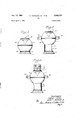
- Fig. l is a front elevational view of a toy embodying various features of the invention, the toy being in a state of compression;
- Fig. 2 is a similar view to Figure 1 showing the toy in a partially expanded condition
- f Fig. ⁇ 3 is a view similar to the preceding figure showing the toy in the fully expanded positions
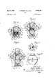
- Fig. 4 is a sectional view of the toy in the position shownin Figure l;
- v Fig. 5 is a sectional view similar tov Figure 4 of the toy in the position shown in Figure 2;
- Fig. 6 is a sectional view of the toy in the position shown in Figure 3;
- Fig. 7 is a fragmentary sectional view taken on line 7-7 in Figure 6;
- Fig. 8 is a fragmentary side elevational view of the toy in the position shown in Figures 3 and 6.
- the toy illustrated comprises a plurality of telescoping sections 9, 11, and 13 and includes means 15 and 17 for biasing the sections into an extended position.
- the toy also includes self-releasable means 19 and 21 for maintaining the sections in a collapsed position for a predetermined length of time.
- the toy is fabricated in the shape of a fanciful man and one of the telescoping sections 9 is adapted to provide a base or pedestal, the second of the telescoping sectionsk 11, is adapted to support a body 23 and the third ofthe telescoping sections 13, is adapted to support a head portion 25. In operation, the three sections 9, 11
- the sections are biased apart by the resilient means 15 and 17 and are held in collapsed position by the means 19 and 21 which are adapted to release after a period of time to progressively change the appearance of the toy as will be hereinafter described.
- the first telescoping section, the secice tion 9, in the illustrated device includes a hollow, open topped, cylindrical member 27 which is providedl with an outwardly extending circumferential flange 29 around its upper end and which is supported on a pedestal or stand 31.
- the pedestal 31 may be fabricated in the form of a pair of feet as illustrated in Figures 1 to 3.
- the lower end of the cylindrical member 27 is closed by a wall 33 and a suction cup 35 which is the means employed for holding the illustrated device in the collapsed position, is mounted in an upwardly directed position on a pin 37 which may be molded integrally with the bottom wall 33.
- the second telescoping section, the section 11, comprises a hollow cylindrical piston 39 which is adapted to Vslide within the cylindrical member 27.
- the piston 39 includes a cylindrical side wall 40 which is adapted to slide within the cylindrical member 27 and an end wall 41 which completes the piston 39, as is illustrated in Figures 4 to 6, inclusive.
- the piston 39 is adapted to slide up and down in the cylindrical member 27 and is adapted to be held by the suction cup 35 for a predetermined time through interengagement of the suction cup 35 with the lower side of the wall 41.
- the piston 39 is biased upwardly in the chamber by the biasing means 15 which takes the form of va coil compression spring 42 which acts between the bottom wall 33 of the cylindrical member 27 and the lower surface of the end wall 41 of the piston 39.
- the compressive force of the spring 42 is such that it takes at least: several seconds for the force of the spring to overcome the holding force of the suction cup 35.
- the body 23 of the device illustrated is generally spherical in shape, and is attached adjacent its upper end to the upper end of the piston 39 as illustrated
- the lower side of the spherically shaped body 23 is provided with a circular opening in which a relating short tube section 43 is supported.
- the tube 43 may form an integral part of the body 23 and is arranged to extend vertically so as to slide upon the outer surface of the cylindrical member 27 to provide a lower bearing surface for the body 23. Interengagement of the tube 43 and the lower side of the flange 29 on the member 27 prevent disengagement of the body 23 from the base section 27 during the use of the device.
- the third telescoping section 13 is supported within the interior of the piston 39 as illustrated.
- This section comprises a second piston member 45 which includes a tubular side wall 47 and an end wall 49 and is proportioned to slide within the interior of the pis-ton 39.
- the end wall 49 is provided with a downwardly extending boss 51 which is adapted to support a suction cup 53 which constitutesthe means 21 for holding the piston member 45 in a collapsed position.
- the suction cup 53 is adapted to engage the upper side of the end wall 41 of the piston 39 and the piston 45 is biased outwardly of the piston 39 by means of a coil compression spring 54 which acts between the upper surface of the end wall 41 of the piston 39 and the lower side of the end wall 49 of the piston 45.
- a coil compression spring 54 which acts between the upper surface of the end wall 41 of the piston 39 and the lower side of the end wall 49 of the piston 45.
- means are provided for preventing the piston 45 from sliding out of the piston 39 and, in the illustrated embodiment, this includes an annular
- the piston member 45 is connected to and is adapted to carry the member 25 which extends out of the body section 23 and in the illustrated device, the member 25 is generally cylindrical in shape and is provided with a fanciful face or the like so as to simulate a head for the toy. Of course, the top of the spherical body is cut away to permit the member 25 to extend out of the body 23.
- the members 9, 11 and 13 are telescopedv together by pressing upon the head 25 so that the toy assumes the configurationV shown in Figure 4.'
- one offthe suction cups 19 or 51 releases, and either the body 23 risesV on thepedestal 27 as shown in Figure 5, or the head 25V Arisesout of ⁇ the body 23 as is shown in ⁇ Figure"6.v V n the hardness of the material for the suction Ac'upsf ⁇ 19. and 51 and for controlling the roughness ofthe surface on which they press, the actionl may be made sequential.
- a pair of hands 56 are pivoted in the sides of the body ⁇ member 23 so ⁇ that they disappear and appear as ⁇ the toy is ⁇ cornpressed and it subsequently releases itsel Y v
- the hands 56 provided are ⁇ fabricated from plastic or the like.A
- Each ⁇ of ⁇ the hands 56 is pivoted on horizontally disposed pins 58, which are supported in suitable bosses 5.9 molded into the' sides of'thebody 23 as illustrated in Figures 6'a ndm7 .y
- Each hand 56 is biased outwardly through a slot 60 in the body 23 by means of a safety pin type spring 61A into an outer extended position (Figs. 5, 6 and 7).
- Each of the hands 56 is provided with a camming section 62 which extends inwardly of the body and which is adapted to engage the annular Harige 29 at the upper edge ofthe cylindrical base member 27.
- the camming section 62 on each of the hands engages the ange which causes the hands to move in'- wardly of the body to the position s hown in Figure 4.
- Sound may also be produced by providing air actuated sound devices 63 and 63a in the chambers defined by the telescoping members.
- a sound reed 63 is provided in the bottom wall 33 of the cylindrical member 27 and a second sound reed 63a is provided in the wall 49 of the piston member 45.
- the pistons 39 and 45 should be so proportioned that a reasonably' air tight construction is obtained so as to provide the necessary pressure to actuate the reeds 63 and 63a.
- a cut-out portion (not shown) should be provided in the head 25 and in the base 31 as is usual in sound producing toys.
- the body could be in the form of a chicken or rooster
- the hands could then take the shape of a tail
- the head could be fabricated to simulate that of a fowl.
- the device could be adapted to simulate substantially any animal figure.'
- a toy comprising a body member having therein a. first tubular section, an extensible member which is adapted to move from a position in said body to a posi# tion out of said body including a second tubular s ection which is slidably interfitted with said rst tubular section in said body, means biasing said member out o f said body, a suction cup secured to one of said members and engageable with the other for maintaining said extensible member in said body for predetermined periods of time, an element carried by said body for movement By properly selei'ztingi ⁇ into and out of said body, and means controlled by the movement of said extensible member to effect movement of said element into and out of said body.
- a toy comprising a body member having therein a tirst tubular section, an extensible member which is adapted to move from a position in said body to a position out of said body including a second tubular section which is slidably intertted with said tirst tubular section in said body, means biasing said extensible member out of said body, a suction cup secured to one of said meinbers and engageable with theother f or maintaining said extensible member in said body for predetermined ⁇ periods of time, an element carried ⁇ by said body for movement into and out of saidfbody, means biasing said element out of said body, and interengageable means on said element and said extensible member for maintaining said element in said body when said member is in said bod M ⁇ 33.51A toy comprising a body, a plurality of coaxially extensible members which'are adapted to move from positions in said body to positions out of said body, means biasing each of said members out of said body, a suction cup carried by each of said members'for' connection ⁇ to said body
- a toy comprising a body, a tubular section in said body, a plurality of members ⁇ whichI are adptedtomove from a position in saidbody to a position out of said body each including a tubular section which is slidably interiitted with saidbody tubular section, means biasing each of said members'out of said body, a suction cupfor ⁇ maintaining each of said members in said body"forp re ⁇ determined periods of time, at least one element 'carried by said body for movement into and ⁇ out of said body, means biasing said element out of 'said body, and means connecting said element to thetubular section associated with one of said members for maintaining said element in1 said body when said one member is in saidbody and which is operable in response to relative movement ⁇ of said one member relative't'o said body ⁇ to"pe ⁇ rrr ⁇ 41it said, element to move out of said body under the influence of its'associated biasing means.
- a toy comprising a body figure and a plurality of appendage elements movably connectedther'eto 'for movement from a position extending fromsaid'body ffigu're t'o a retracted position in said body, resilient means urging said appendage elements to said extended positions, and separate selfireleasable connections between said appendage elements and said body figure for holding said appendage elements in retracted positionforindenite periods whereby said appendage elementsare'relased and move to said extended positions in'sequencefsaid appendage elements being arranged on saidbody'fgulfe for movement'into said body figure by asingleapplid motion.
Landscapes
- Toys (AREA)
Description
Jan. 17, 1961 v c. PEARsoN,-JR., ETAL 2,968,121
TOY. Filed April 4, 1958 l2 sheets-sheet 1 Fg. Z y '/3 J @06 :j .f
Jan. 17, 1961 c. PEARsoN, JR., l-:T AL
TOY
Filed April 4, 1958 2 Sheets- Sheet 2 nited States Patent TOY Charles Pearson, Jr., Elmhurst, Ill., and Marvin l. Glass, 57 E. Ohio St., Chicago, Ill.; said Pearson assignor to said Glass Filed Apr. 4, 1958, Sel'. No. 726,509
Claims. (Cl. 46-118) The present invention relates generally to a toy and more particularly to a telescoping toy which is adapted to ,be compressed into a configuration and which after predetermined periods of time is operable to expand into a different configuration.
A toy in accordance with the present invention is particularly adapted for use by small children and is designed to provide an air of mystery and a measure of suspense. The principal object of the invention is the provision of a toy which is adapted to change configuration after perdetermined times. A further object of the invention is the provision of a toy which can be operated by a small child and which will maintainthe interest of such child. Another object of the invention is the provision of such a toy which is durable and which is economical to manufacture.
Other objects and advantages of the invention will become known from the following description and the accompanying drawings of one preferred embodiment of the invention.
, In thev drawings:
i Fig. l is a front elevational view of a toy embodying various features of the invention, the toy being in a state of compression;
Fig. 2 is a similar view to Figure 1 showing the toy in a partially expanded condition;
f Fig.` 3 is a view similar to the preceding figure showing the toy in the fully expanded positions;
Fig. 4 is a sectional view of the toy in the position shownin Figure l;
v Fig. 5 is a sectional view similar tovFigure 4 of the toy in the position shown in Figure 2;
Fig. 6 is a sectional view of the toy in the position shown in Figure 3;
Fig. 7 is a fragmentary sectional view taken on line 7-7 in Figure 6; and
Fig. 8 is a fragmentary side elevational view of the toy in the position shown in Figures 3 and 6.
Basically, the toy illustrated comprises a plurality of telescoping sections 9, 11, and 13 and includes means 15 and 17 for biasing the sections into an extended position. The toy also includes self-releasable means 19 and 21 for maintaining the sections in a collapsed position for a predetermined length of time. In the embodiment illustrated, the toy is fabricated in the shape of a fanciful man and one of the telescoping sections 9 is adapted to provide a base or pedestal, the second of the telescoping sectionsk 11, is adapted to support a body 23 and the third ofthe telescoping sections 13, is adapted to support a head portion 25. In operation, the three sections 9, 11
and 13 are collapsed together so that in appearance all that one sees is the body section 23. The sections are biased apart by the resilient means 15 and 17 and are held in collapsed position by the means 19 and 21 which are adapted to release after a period of time to progressively change the appearance of the toy as will be hereinafter described.
More specifically, the first telescoping section, the secice tion 9, in the illustrated device includes a hollow, open topped, cylindrical member 27 which is providedl with an outwardly extending circumferential flange 29 around its upper end and which is supported on a pedestal or stand 31. The pedestal 31 may be fabricated in the form of a pair of feet as illustrated in Figures 1 to 3. The lower end of the cylindrical member 27 is closed by a wall 33 and a suction cup 35 which is the means employed for holding the illustrated device in the collapsed position, is mounted in an upwardly directed position on a pin 37 which may be molded integrally with the bottom wall 33.
The second telescoping section, the section 11, comprises a hollow cylindrical piston 39 which is adapted to Vslide within the cylindrical member 27. The piston 39 includes a cylindrical side wall 40 which is adapted to slide within the cylindrical member 27 and an end wall 41 which completes the piston 39, as is illustrated in Figures 4 to 6, inclusive. The piston 39 is adapted to slide up and down in the cylindrical member 27 and is adapted to be held by the suction cup 35 for a predetermined time through interengagement of the suction cup 35 with the lower side of the wall 41. As illustrated, the piston 39 is biased upwardly in the chamber by the biasing means 15 which takes the form of va coil compression spring 42 which acts between the bottom wall 33 of the cylindrical member 27 and the lower surface of the end wall 41 of the piston 39. Of course, the compressive force of the spring 42 is such that it takes at least: several seconds for the force of the spring to overcome the holding force of the suction cup 35.
The body 23 of the device illustrated, is generally spherical in shape, and is attached adjacent its upper end to the upper end of the piston 39 as illustrated The lower side of the spherically shaped body 23 is provided with a circular opening in which a relating short tube section 43 is supported. The tube 43 may form an integral part of the body 23 and is arranged to extend vertically so as to slide upon the outer surface of the cylindrical member 27 to provide a lower bearing surface for the body 23. Interengagement of the tube 43 and the lower side of the flange 29 on the member 27 prevent disengagement of the body 23 from the base section 27 during the use of the device.
The third telescoping section 13 is supported within the interior of the piston 39 as illustrated. This section comprises a second piston member 45 which includes a tubular side wall 47 and an end wall 49 and is proportioned to slide within the interior of the pis-ton 39. The end wall 49 is provided with a downwardly extending boss 51 which is adapted to support a suction cup 53 which constitutesthe means 21 for holding the piston member 45 in a collapsed position. The suction cup 53 is adapted to engage the upper side of the end wall 41 of the piston 39 and the piston 45 is biased outwardly of the piston 39 by means of a coil compression spring 54 which acts between the upper surface of the end wall 41 of the piston 39 and the lower side of the end wall 49 of the piston 45. Of course, means are provided for preventing the piston 45 from sliding out of the piston 39 and, in the illustrated embodiment, this includes an annular rim 55 which extends over the opening in the interior of the piston 39 so as to provide a stop for the piston 45.
The piston member 45 is connected to and is adapted to carry the member 25 which extends out of the body section 23 and in the illustrated device, the member 25 is generally cylindrical in shape and is provided with a fanciful face or the like so as to simulate a head for the toy. Of course, the top of the spherical body is cut away to permit the member 25 to extend out of the body 23.
In operation, the members 9, 11 and 13 are telescopedv together by pressing upon the head 25 so that the toy assumes the configurationV shown in Figure 4.' After a predetermined time, one offthe suction cups 19 or 51 releases, and either the body 23 risesV on thepedestal 27 as shown in Figure 5, or the head 25V Arisesout of `the body 23 as is shown in `Figure"6.v V n the hardness of the material for the suction Ac'upsf`19. and 51 and for controlling the roughness ofthe surface on which they press, the actionl may be made sequential.
However, if the material and the surface characteristics' are the same, the action which will occur first will `be a" matter of chance. After both suction cups 19 and 51 are released, the ligure will assume the position shown inFigures.
In order to provide more action in the toy, a pair of hands 56 are pivoted in the sides of the body `member 23 so` that they disappear and appear as` the toy is` cornpressed and it subsequently releases itsel Y v In the illustrated embodiment, the hands 56 provided, are `fabricated from plastic or the like.A Each `of `the hands 56 is pivoted on horizontally disposed pins 58, which are supported in suitable bosses 5.9 molded into the' sides of'thebody 23 as illustrated in Figures 6'a ndm7 .y Each hand 56is biased outwardly through a slot 60 in the body 23 by means of a safety pin type spring 61A into an outer extended position (Figs. 5, 6 and 7). One of'` the leaves of the spring 61 bears against the side of the body 23 and the other'of the leaves is connected 1n a hole in the hand, the eye of the springa being disposed around the pin 58 as illustrated. Each of the hands 56 is provided with a camming section 62 which extends inwardly of the body and which is adapted to engage the annular Harige 29 at the upper edge ofthe cylindrical base member 27. Thus, as `the body 23 is moved downwardly on its pedestal along the cylindrical member 27, the camming section 62 on each of the hands engages the ange which causes the hands to move in'- wardly of the body to the position s hown in Figure 4.
Sound may also be produced by providing air actuated sound devices 63 and 63a in the chambers defined by the telescoping members. In the illustrated toy, a sound reed 63 is provided in the bottom wall 33 of the cylindrical member 27 and a second sound reed 63a is provided in the wall 49 of the piston member 45. If sound reeds are to be employed to produce a noise as the device telescopes and extends, the pistons 39 and 45 should be so proportioned that a reasonably' air tight construction is obtained so as to provide the necessary pressure to actuate the reeds 63 and 63a. Also in order to permit the noise produced to escape, a cut-out portion (not shown) should be provided in the head 25 and in the base 31 as is usual in sound producing toys.
While the invention has been described in connection with a fanciful man, it can take various other embodiments. For example, the body could be in the form of a chicken or rooster, the hands could then take the shape of a tail, and the head could be fabricated to simulate that of a fowl. In a similar manner, the device could be adapted to simulate substantially any animal figure.'
Various features of the invention which are believed to be new, are set forth in the appended claims.
We claim:
l. A toy comprising a body member having therein a. first tubular section, an extensible member which is adapted to move from a position in said body to a posi# tion out of said body including a second tubular s ection which is slidably interfitted with said rst tubular section in said body, means biasing said member out o f said body, a suction cup secured to one of said members and engageable with the other for maintaining said extensible member in said body for predetermined periods of time, an element carried by said body for movement By properly selei'ztingi` into and out of said body, and means controlled by the movement of said extensible member to effect movement of said element into and out of said body.
2. A toy comprising a body member having therein a tirst tubular section, an extensible member which is adapted to move from a position in said body to a position out of said body including a second tubular section which is slidably intertted with said tirst tubular section in said body, means biasing said extensible member out of said body, a suction cup secured to one of said meinbers and engageable with theother f or maintaining said extensible member in said body for predetermined`` periods of time, an element carried` by said body for movement into and out of saidfbody, means biasing said element out of said body, and interengageable means on said element and said extensible member for maintaining said element in said body when said member is in said bod M`33.51A toy comprising a body, a plurality of coaxially extensible members which'are adapted to move from positions in said body to positions out of said body, means biasing each of said members out of said body, a suction cup carried by each of said members'for' connection` to said body for predetermined periods ofV time afterxwlnch said member moves Vto a position out of saidbody, Aan element carried by's'aid body for movement into and out ofsaid body, means biasing 'said velementout of said body and means connecting said element to one ofsaid ex# tensible members forfmaintaining said element` in said body when said one member isin said body.
' Y4. A toy comprising a body, a tubular section in said body, a plurality of members `whichI are adptedtomove from a position in saidbody to a position out of said body each including a tubular section which is slidably interiitted with saidbody tubular section, means biasing each of said members'out of said body, a suction cupfor` maintaining each of said members in said body"forp re` determined periods of time, at least one element 'carried by said body for movement into and `out of said body, means biasing said element out of 'said body, and means connecting said element to thetubular section associated with one of said members for maintaining said element in1 said body when said one member is in saidbody and which is operable in response to relative movement `of said one member relative't'o said body `to"pe`rrr`41it said, element to move out of said body under the influence of its'associated biasing means. f i* 5,. A toy comprising a body figure and a plurality of appendage elements movably connectedther'eto 'for movement from a position extending fromsaid'body ffigu're t'o a retracted position in said body, resilient means urging said appendage elements to said extended positions, and separate selfireleasable connections between said appendage elements and said body figure for holding said appendage elements in retracted positionforindenite periods whereby said appendage elementsare'relased and move to said extended positions in'sequencefsaid appendage elements being arranged on saidbody'fgulfe for movement'into said body figure by asingleapplid motion. i
References Cited in the tile of this patent UNITED STATES PaTENTs 821,468 Dashiell May 2,2. `1,906 1,130,497 Dunham -Mar. 2, 1915 1,657,936 `Nebel Jan. 31, 19,28 1,918,122 Naue July `11, 1933 2,303,652 McGaugh D ec. ,1, 1942 2,598,807 Lawson June 3, `19,52 2,774,179 Zalkind Dec. 18. 195,6 2,885,824 Lemelson May 12, 1959
Priority Applications (1)
| Application Number | Priority Date | Filing Date | Title |
|---|---|---|---|
| US726509A US2968121A (en) | 1958-04-04 | 1958-04-04 | Toy |
Applications Claiming Priority (1)
| Application Number | Priority Date | Filing Date | Title |
|---|---|---|---|
| US726509A US2968121A (en) | 1958-04-04 | 1958-04-04 | Toy |
Publications (1)
| Publication Number | Publication Date |
|---|---|
| US2968121A true US2968121A (en) | 1961-01-17 |
Family
ID=24918906
Family Applications (1)
| Application Number | Title | Priority Date | Filing Date |
|---|---|---|---|
| US726509A Expired - Lifetime US2968121A (en) | 1958-04-04 | 1958-04-04 | Toy |
Country Status (1)
| Country | Link |
|---|---|
| US (1) | US2968121A (en) |
Cited By (36)
| Publication number | Priority date | Publication date | Assignee | Title |
|---|---|---|---|---|
| US3176430A (en) * | 1962-05-28 | 1965-04-06 | Mattel Inc | Jumping figure and game |
| US3581434A (en) * | 1969-09-11 | 1971-06-01 | Jay V Zimmerman Co | Rocket-simulative toy |
| US3896584A (en) * | 1973-11-14 | 1975-07-29 | Marvin Glass & Associates | Figure toy with variable sounding means |
| US4164827A (en) * | 1977-10-31 | 1979-08-21 | Kohner, Inc. | Action toy |
| US4262445A (en) * | 1979-02-12 | 1981-04-21 | Henry Orenstein | Controllable response systems |
| US5162013A (en) * | 1991-06-19 | 1992-11-10 | Mike Bowling Enterprises, Inc. | Transformable toy |
| US5700178A (en) * | 1996-08-14 | 1997-12-23 | Fisher-Price, Inc. | Emotional expression character |
| US5797815A (en) * | 1997-02-06 | 1998-08-25 | Goldman Toy Group, Inc. | Pop-open throwing toy with controllable opening delay and method of operating same |
| USD434457S (en) | 1998-03-05 | 2000-11-28 | Goldman Toy Group, Inc. | Collapsible toy |
| US20040116042A1 (en) * | 2002-09-03 | 2004-06-17 | Emoff Michael J. | Bobble-head doll with deformable head |
| USD496077S1 (en) | 2004-02-06 | 2004-09-14 | Jw Pet Company | Devil toy |
| US6805077B2 (en) | 2003-02-25 | 2004-10-19 | Tucker Toys Inc. | Collapsible dog toy |
| US6863588B1 (en) * | 2003-12-01 | 2005-03-08 | Kwong Wing Chu | Collapsible throwing toy and its associated method of manufacture |
| USD565806S1 (en) * | 2006-09-14 | 2008-04-01 | Jw Pet Company, Inc. | Pet toys |
| USD565807S1 (en) | 2006-09-21 | 2008-04-01 | Jw Pet Company, Inc. | Pet toy |
| WO2008135745A3 (en) * | 2007-05-05 | 2009-01-15 | Evolve Npd Ltd | Play structure |
| US20100291831A1 (en) * | 2008-01-10 | 2010-11-18 | Sega Toys Co., Ltd. | Toy |
| US7862397B1 (en) * | 2008-05-07 | 2011-01-04 | Hasbro, Inc. | Mechanical apparatus operated by a slight lateral force |
| USD762567S1 (en) * | 2013-10-11 | 2016-08-02 | Mimoco | USB battery charger |
| US10112121B2 (en) | 2015-05-28 | 2018-10-30 | Tucker International Llc | Toy assembly that converts between a spherical shape and a flying disc shape |
| US10220324B1 (en) * | 2015-12-22 | 2019-03-05 | Hasbro, Inc. | Play apparatus and methods featuring modeling compound can actuating toy items |
| US20190168127A1 (en) * | 2017-12-06 | 2019-06-06 | Darwin William Fernandez | Rotating toy |
| WO2019158693A1 (en) * | 2018-02-19 | 2019-08-22 | Oger Emmanuel | Connected festive device made of chocolate |
| US10602719B2 (en) * | 2016-06-15 | 2020-03-31 | Bencoo, Inc. | Animated squeaky pet toy and method for producing a squeaky noise |
| US10695687B2 (en) | 2017-10-03 | 2020-06-30 | Darwin William Fernandez | Model Toy croms balls |
| US10864452B2 (en) | 2018-01-22 | 2020-12-15 | Darwin William Fernandez | Toy with two bodies and an ejectable gear and retraction mechanism |
| US11305206B1 (en) * | 2019-04-24 | 2022-04-19 | Procreate Brands LLC | Toy systems with suction portion for audible interaction and entertainment |
| US11376515B1 (en) * | 2021-06-29 | 2022-07-05 | Spin Master Ltd. | Transformable toy |
| US11389741B2 (en) * | 2018-12-12 | 2022-07-19 | Mattel-Mega Holdings (Us), Llc | Transformable building block |
| US20220339551A1 (en) * | 2019-10-01 | 2022-10-27 | Lego A/S | Transformable modular toy element |
| US11712636B1 (en) | 2022-08-12 | 2023-08-01 | Spin Master Ltd. | Transformable toy |
| USD1029155S1 (en) | 2021-06-25 | 2024-05-28 | Spin Master Ltd. | Toy |
| US20240173637A1 (en) * | 2022-11-30 | 2024-05-30 | Shenzhen Beipengxing Technology Co., Ltd. | Toy |
| US12011675B1 (en) * | 2023-03-31 | 2024-06-18 | DiscoNifty Ltd. | Rotationally transformable toy between a first configuration and a second configuration |
| US12029993B1 (en) * | 2023-10-11 | 2024-07-09 | Jast Company Limited | Egg-shaped pop-up toy with electronic effects |
| US12576341B2 (en) | 2022-08-12 | 2026-03-17 | Spin Master Ltd. | Transformable toy |
Citations (8)
| Publication number | Priority date | Publication date | Assignee | Title |
|---|---|---|---|---|
| US821468A (en) * | 1905-11-28 | 1906-05-22 | Raymond G Dashiell | Toy. |
| US1130497A (en) * | 1914-07-17 | 1915-03-02 | James W Dunham | Stand. |
| US1657936A (en) * | 1923-03-10 | 1928-01-31 | Miguel E Nebel | Jumping-figure toy |
| US1918122A (en) * | 1933-02-15 | 1933-07-11 | Richard J Naue | Mechanical toy |
| US2303652A (en) * | 1940-09-10 | 1942-12-01 | Mcgaugh Nan Jo | Toy |
| US2598807A (en) * | 1948-10-29 | 1952-06-03 | Jr William E Lawson | Expansible toy and bank |
| US2774179A (en) * | 1953-11-25 | 1956-12-18 | Albert M Zalkind | Pounding toy |
| US2885824A (en) * | 1953-11-13 | 1959-05-12 | Jerome H Lemelson | Sounding jumping toy |
-
1958
- 1958-04-04 US US726509A patent/US2968121A/en not_active Expired - Lifetime
Patent Citations (8)
| Publication number | Priority date | Publication date | Assignee | Title |
|---|---|---|---|---|
| US821468A (en) * | 1905-11-28 | 1906-05-22 | Raymond G Dashiell | Toy. |
| US1130497A (en) * | 1914-07-17 | 1915-03-02 | James W Dunham | Stand. |
| US1657936A (en) * | 1923-03-10 | 1928-01-31 | Miguel E Nebel | Jumping-figure toy |
| US1918122A (en) * | 1933-02-15 | 1933-07-11 | Richard J Naue | Mechanical toy |
| US2303652A (en) * | 1940-09-10 | 1942-12-01 | Mcgaugh Nan Jo | Toy |
| US2598807A (en) * | 1948-10-29 | 1952-06-03 | Jr William E Lawson | Expansible toy and bank |
| US2885824A (en) * | 1953-11-13 | 1959-05-12 | Jerome H Lemelson | Sounding jumping toy |
| US2774179A (en) * | 1953-11-25 | 1956-12-18 | Albert M Zalkind | Pounding toy |
Cited By (49)
| Publication number | Priority date | Publication date | Assignee | Title |
|---|---|---|---|---|
| US3176430A (en) * | 1962-05-28 | 1965-04-06 | Mattel Inc | Jumping figure and game |
| US3581434A (en) * | 1969-09-11 | 1971-06-01 | Jay V Zimmerman Co | Rocket-simulative toy |
| US3896584A (en) * | 1973-11-14 | 1975-07-29 | Marvin Glass & Associates | Figure toy with variable sounding means |
| US4164827A (en) * | 1977-10-31 | 1979-08-21 | Kohner, Inc. | Action toy |
| US4262445A (en) * | 1979-02-12 | 1981-04-21 | Henry Orenstein | Controllable response systems |
| US5162013A (en) * | 1991-06-19 | 1992-11-10 | Mike Bowling Enterprises, Inc. | Transformable toy |
| US5700178A (en) * | 1996-08-14 | 1997-12-23 | Fisher-Price, Inc. | Emotional expression character |
| US5797815A (en) * | 1997-02-06 | 1998-08-25 | Goldman Toy Group, Inc. | Pop-open throwing toy with controllable opening delay and method of operating same |
| USD434457S (en) | 1998-03-05 | 2000-11-28 | Goldman Toy Group, Inc. | Collapsible toy |
| US20040116042A1 (en) * | 2002-09-03 | 2004-06-17 | Emoff Michael J. | Bobble-head doll with deformable head |
| US6805077B2 (en) | 2003-02-25 | 2004-10-19 | Tucker Toys Inc. | Collapsible dog toy |
| US6863588B1 (en) * | 2003-12-01 | 2005-03-08 | Kwong Wing Chu | Collapsible throwing toy and its associated method of manufacture |
| USD501898S1 (en) | 2004-02-06 | 2005-02-15 | Ryan Rutherford | Angel toy |
| USD496077S1 (en) | 2004-02-06 | 2004-09-14 | Jw Pet Company | Devil toy |
| USD565806S1 (en) * | 2006-09-14 | 2008-04-01 | Jw Pet Company, Inc. | Pet toys |
| USD565807S1 (en) | 2006-09-21 | 2008-04-01 | Jw Pet Company, Inc. | Pet toy |
| USD576359S1 (en) | 2006-09-21 | 2008-09-02 | Jw Pet Company, Inc. | Pet toy |
| WO2008135745A3 (en) * | 2007-05-05 | 2009-01-15 | Evolve Npd Ltd | Play structure |
| US8517791B2 (en) * | 2008-01-10 | 2013-08-27 | Spin Master Ltd. | Toy |
| US20100291831A1 (en) * | 2008-01-10 | 2010-11-18 | Sega Toys Co., Ltd. | Toy |
| US7862397B1 (en) * | 2008-05-07 | 2011-01-04 | Hasbro, Inc. | Mechanical apparatus operated by a slight lateral force |
| USD762567S1 (en) * | 2013-10-11 | 2016-08-02 | Mimoco | USB battery charger |
| US10112121B2 (en) | 2015-05-28 | 2018-10-30 | Tucker International Llc | Toy assembly that converts between a spherical shape and a flying disc shape |
| US10220324B1 (en) * | 2015-12-22 | 2019-03-05 | Hasbro, Inc. | Play apparatus and methods featuring modeling compound can actuating toy items |
| US10602719B2 (en) * | 2016-06-15 | 2020-03-31 | Bencoo, Inc. | Animated squeaky pet toy and method for producing a squeaky noise |
| US10695687B2 (en) | 2017-10-03 | 2020-06-30 | Darwin William Fernandez | Model Toy croms balls |
| US20190168127A1 (en) * | 2017-12-06 | 2019-06-06 | Darwin William Fernandez | Rotating toy |
| US11219839B2 (en) * | 2017-12-06 | 2022-01-11 | Darwin William Fernandez | Button activated transformable rotating toy |
| US10864452B2 (en) | 2018-01-22 | 2020-12-15 | Darwin William Fernandez | Toy with two bodies and an ejectable gear and retraction mechanism |
| FR3077993A1 (en) * | 2018-02-19 | 2019-08-23 | Emmanuel Oger | FESTIVE DEVICE CONNECTED IN CHOCOLATE |
| WO2019158693A1 (en) * | 2018-02-19 | 2019-08-22 | Oger Emmanuel | Connected festive device made of chocolate |
| US11389741B2 (en) * | 2018-12-12 | 2022-07-19 | Mattel-Mega Holdings (Us), Llc | Transformable building block |
| US11305206B1 (en) * | 2019-04-24 | 2022-04-19 | Procreate Brands LLC | Toy systems with suction portion for audible interaction and entertainment |
| US11964218B2 (en) * | 2019-04-24 | 2024-04-23 | Procreate Brands, LLC | Toy systems with suction portion for audible interaction and entertainment |
| USD972044S1 (en) | 2019-04-24 | 2022-12-06 | Procreate Brands LLC | Snap toy |
| US11717763B1 (en) * | 2019-04-24 | 2023-08-08 | Procreate Brands LLC | Toy systems with suction portion for audible interaction and entertainment |
| US20230330549A1 (en) * | 2019-04-24 | 2023-10-19 | Procreate Brands, LLC | Toy Systems With Suction Portion for Audible Interaction and Entertainment |
| US20220339551A1 (en) * | 2019-10-01 | 2022-10-27 | Lego A/S | Transformable modular toy element |
| US12151181B2 (en) * | 2019-10-01 | 2024-11-26 | Lego A/S | Transformable modular toy element |
| USD1029155S1 (en) | 2021-06-25 | 2024-05-28 | Spin Master Ltd. | Toy |
| US11376515B1 (en) * | 2021-06-29 | 2022-07-05 | Spin Master Ltd. | Transformable toy |
| EP4252881A3 (en) * | 2021-06-29 | 2024-01-03 | Spin Master Ltd. | Transformable toy |
| US20220410025A1 (en) * | 2021-06-29 | 2022-12-29 | Spin Master Ltd. | Transformable toy |
| US12285702B2 (en) * | 2021-06-29 | 2025-04-29 | Spin Master Ltd. | Transformable toy |
| US11712636B1 (en) | 2022-08-12 | 2023-08-01 | Spin Master Ltd. | Transformable toy |
| US12576341B2 (en) | 2022-08-12 | 2026-03-17 | Spin Master Ltd. | Transformable toy |
| US20240173637A1 (en) * | 2022-11-30 | 2024-05-30 | Shenzhen Beipengxing Technology Co., Ltd. | Toy |
| US12011675B1 (en) * | 2023-03-31 | 2024-06-18 | DiscoNifty Ltd. | Rotationally transformable toy between a first configuration and a second configuration |
| US12029993B1 (en) * | 2023-10-11 | 2024-07-09 | Jast Company Limited | Egg-shaped pop-up toy with electronic effects |
Similar Documents
| Publication | Publication Date | Title |
|---|---|---|
| US2968121A (en) | Toy | |
| US2760303A (en) | Articulated figure toy | |
| US3526991A (en) | Delay action play unit | |
| US5162013A (en) | Transformable toy | |
| US5029700A (en) | Receptacle and amusement device | |
| US11241634B2 (en) | Figurine with magnetic assembly components | |
| US3009284A (en) | Doll construction | |
| JP2008132355A (en) | Transformable toy | |
| US2912791A (en) | Toy | |
| HK15984A (en) | Vehicle for children | |
| US3828467A (en) | Doll | |
| US2979844A (en) | Plastic party favor basket construction | |
| US4291487A (en) | Inflatable article with external means to control internal movement | |
| US2860368A (en) | Swivel glide unit for furniture legs | |
| US1710989A (en) | Clinging figure | |
| US20120309262A1 (en) | Collectable helmet with interactive features | |
| US3037771A (en) | Plastic bowling pins | |
| US1456422A (en) | Jointed doll | |
| US2429928A (en) | Doll | |
| US3125827A (en) | ostrander | |
| US2133635A (en) | Doll | |
| CN206745975U (en) | A kind of doll that can be bounced | |
| US2560481A (en) | Animated bird toy | |
| US3287847A (en) | Mechanically actuated doll with articulated legs | |
| CN211935559U (en) | Transformable dinosaur toy |