US2981426A - Apparatus for placing roof deck slabs - Google Patents
Apparatus for placing roof deck slabs Download PDFInfo
- Publication number
- US2981426A US2981426A US741609A US74160958A US2981426A US 2981426 A US2981426 A US 2981426A US 741609 A US741609 A US 741609A US 74160958 A US74160958 A US 74160958A US 2981426 A US2981426 A US 2981426A
- Authority
- US
- United States
- Prior art keywords
- slab
- slabs
- roof
- members
- roof deck
- Prior art date
- Legal status (The legal status is an assumption and is not a legal conclusion. Google has not performed a legal analysis and makes no representation as to the accuracy of the status listed.)
- Expired - Lifetime
Links
- 238000009434 installation Methods 0.000 description 4
- 230000006378 damage Effects 0.000 description 3
- 238000005452 bending Methods 0.000 description 2
- 239000000463 material Substances 0.000 description 2
- 239000002184 metal Substances 0.000 description 2
- 238000000034 method Methods 0.000 description 2
- 229910000831 Steel Inorganic materials 0.000 description 1
- 239000000956 alloy Substances 0.000 description 1
- 229910045601 alloy Inorganic materials 0.000 description 1
- 230000015572 biosynthetic process Effects 0.000 description 1
- 238000010276 construction Methods 0.000 description 1
- 238000012986 modification Methods 0.000 description 1
- 230000004048 modification Effects 0.000 description 1
- 230000000750 progressive effect Effects 0.000 description 1
- 239000012858 resilient material Substances 0.000 description 1
- 239000010959 steel Substances 0.000 description 1
- 239000000725 suspension Substances 0.000 description 1
- 238000003466 welding Methods 0.000 description 1
Images
Classifications
-
- E—FIXED CONSTRUCTIONS
- E01—CONSTRUCTION OF ROADS, RAILWAYS, OR BRIDGES
- E01C—CONSTRUCTION OF, OR SURFACES FOR, ROADS, SPORTS GROUNDS, OR THE LIKE; MACHINES OR AUXILIARY TOOLS FOR CONSTRUCTION OR REPAIR
- E01C19/00—Machines, tools or auxiliary devices for preparing or distributing paving materials, for working the placed materials, or for forming, consolidating, or finishing the paving
- E01C19/52—Apparatus for laying individual preformed surfacing elements, e.g. kerbstones
- E01C19/526—Apparatus for laying individual preformed surfacing elements, e.g. kerbstones hand operated
- E01C19/528—Apparatus for laying individual preformed surfacing elements, e.g. kerbstones hand operated with wheels
-
- B—PERFORMING OPERATIONS; TRANSPORTING
- B62—LAND VEHICLES FOR TRAVELLING OTHERWISE THAN ON RAILS
- B62B—HAND-PROPELLED VEHICLES, e.g. HAND CARTS OR PERAMBULATORS; SLEDGES
- B62B1/00—Hand carts having only one axis carrying one or more transport wheels; Equipment therefor
- B62B1/02—Hand carts having only one axis carrying one or more transport wheels; Equipment therefor in which the wheel axis is disposed between the load and the handles
- B62B1/06—Hand carts having only one axis carrying one or more transport wheels; Equipment therefor in which the wheel axis is disposed between the load and the handles involving means for grappling or securing in place objects to be carried; Loading or unloading equipment
-
- E—FIXED CONSTRUCTIONS
- E04—BUILDING
- E04G—SCAFFOLDING; FORMS; SHUTTERING; BUILDING IMPLEMENTS OR AIDS, OR THEIR USE; HANDLING BUILDING MATERIALS ON THE SITE; REPAIRING, BREAKING-UP OR OTHER WORK ON EXISTING BUILDINGS
- E04G21/00—Preparing, conveying, or working-up building materials or building elements in situ; Other devices or measures for constructional work
- E04G21/14—Conveying or assembling building elements
- E04G21/16—Tools or apparatus
- E04G21/167—Tools or apparatus specially adapted for working-up plates, panels or slab shaped building elements
Definitions
- My invention relates to apparatus for transporting and locating slabs or sheets, for example, in the formation of a roof deck, etc. More particularly, this invention relates to an apparatus which can perform these operations in such locations that the said slabs or sheets may be placed upon spaced apart supporting members such as roof joists, which have an open space between them, without jeopardizing the operator.
- This device may be generally referred to as a dolly and has been successfully demonstrated in the installation of roof deck.
- This apparatus My invention is unique in that it enables a single workman to pick up, transport and place in position a slab or sheet of considerable weight.
- One object of my invention, among others is to provide a method of installing roof deck without the use of a crane or subjecting the worker to the danger of working over open beams or framework.
- my invention consists of a tubular frame supported by two wheels'
- the frame at the front end cantilevers out over the wheels and is so designed to extend across a slab or sheet and engage the outer side edge portions, i.e., the edge portion remote from the operator.
- the slab or section is lifted and may be wheeled to its point of installation.
- the wheels roll on the deck already installed.
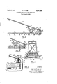
- Fig. 1 is a side elevational view of the apparatus illustrating the suspension of a roof deck slab over the ,open area of the supporting beams and ready for positioning;
- Fig. 2 is a side elevation showing the slab in position and about to be disengaged from the apparatus
- Fig. 3 is an end view illustrating the construction of the apparatus and the adjusting means to permit the use of the device for positioning slabs of differing thickness; and t Fig. 4 is an enlarged cross-sectional view of the adjustable holding mechanism.
- the device consists of a main frame comprised of support members or side bars 10 and 11 which may be made of metal or other type of tubing of a light weight but strong alloy. These members 10 and 11 are bound together by the crossmembers 12 and 13 and may be made of the same material.
- the upper end of the frame members 10 and 11 which extends behind the wheels 14 is of such length as to provide the operator with sufficient leverage to pick up slabs of considerable weight and withgreat ease.
- the lower end of this apparatus constitutes the holding mechanism for the slabs and is provided by bending the frame members 10 and 11 to form substantially vertical may be constructed either by bending frame members 10 and 11 to form the portions 15 and 16 or in any other manner such as by welding together individual pieces to form approximately the same U-shaped structure.
- rigidity of the frame is accomplished by providing, in addition to members 12 and 13, parallel members 23, 24 and 25 which join the side bars 10 and 11 together.
- Wheels 14 are mounted on a common axle 31 supported by the extensions 32 and 33 of the frame members 10 and 11.
- the wheels are free running on the axle 31 and they are provided with an exterior surface or tires of rubber or some material which will not damage the slabs 35 previously laid and subsequently used as a footing or floor.
- the axle or fulcrum 31 for the wheels 14 is spaced from the slab holding end of the frame a distance conducive to providing great leverage when force is applied to the member 25 at the opposite end of the frame members 10 and 11. With the application of such force to member 25 the frame will be tilted about the fulcrum 31 raising the contact members 38 and 39 and the slab 35. This raising motion will permit the slab 35 to tilt on the pad 38, due to the overhang of the major portion of the slab, until its inner end and surface 50 contacts the pad 39. This contact will automatically lock the.
- the subject device is in the form of a simple or first class lever and arranged at one end to utilize the weight of the object to be lifted as the force for retaining the object upon the lever.
- the slab 35 is held by the apparatus as shown in Fig. 4.
- the slab support jaws 36 and 37 are covered with resilient padding 38 and 39.
- the resilient member 38 is stationary, being firmly attached to the metal plate 36, whereas the resilient member 39 is arranged to be raised or lowered with the adjusting screws 40 which are positioned along the length of the bracket 42.
- the resilient member 39 may take the form of two separate pads positioned under and attached to the screws 40 or it maybe a separate pad which may extend through the full width and length of the member 42.
- the member 42 is provided with two lugs 45 extending in a horizontal plane and threaded to allow vertical travel of the jaws 37 on the adjusting screws 40.
- Two holes 43 are provided in the horizontal section of the member 42 to allow the jaws 37 of the screws 40 to pass through the member 42 and provide the adjustable contact between the resilient members 38 and 39 and the top and bottom faces 50 and 51 of the slab 35.
- my invention When used as an apparatus to install roof deck, my invention results in a new and unique method of installation.
- the dolly is wheeled up to the slab 35 and the holding end of the apparatus is lowered to a position permitting the support member 38 to be brought underneath the further edge of the slab.
- the worker then pulls the dolly toward the slab, causing it to slide in between the pieces of resilient material 38 and 39.
- the outer edge of the slab will now be firmly against the plate 46 and by pressing down on the handles 10 and 11, which are long enough to give great leverage, the slab 35 will be lifted and may be wheeled to the then existing edge of the roof.
- roof slabs 35 may be accomplished without the need of the worker subjecting himself to unnecessary risks or hazards.
- Apparatus for transporting and placing deck slabs in the forming of a roof or floor structure comprising a wheeled, open elongated frame including a pair of spaced parallel side bars, a substantially U-shaped holder formed as an extension of each side bar at one end thereof, said holders being spaced apart transversely of the frame, and each having an open end facing in the direction of the other end of the frame, a vertically disposed, elongated plate extending between and fixed to said holders, a right angle bracket extending between said 35 g aesmae holders and being fixed at its ends to said holders, said bracket having the vertical portion thereof connected to said side bars and the horizontal portion thereof connected to the base of the U-shaped portion, said horizontal portion having a plurality of openings formed therein, a plurality of lugs connected to said vertical portion of said bracket, overlying said openings in said horizontal portion, and having female threads therein vertically aligned with said openings, a male adjusting screw threaded through each said lug,
Landscapes
- Engineering & Computer Science (AREA)
- Architecture (AREA)
- Mechanical Engineering (AREA)
- Civil Engineering (AREA)
- Structural Engineering (AREA)
- Chemical & Material Sciences (AREA)
- Combustion & Propulsion (AREA)
- Transportation (AREA)
- Conveying And Assembling Of Building Elements In Situ (AREA)
Description
April 25, 1961 H. E. CASEY 2,981,426
APPARATUS FOR PLACING ROOF DECK SLABS Filed June 12, 1958 v I l 0/ if. y 16 fi i 5/1 i m HTTO RIVE Y8 Z m/AM United States Patent 2,981,426 APPAFRATUS FOR PLACING noon DECK SLABS My invention relates to apparatus for transporting and locating slabs or sheets, for example, in the formation of a roof deck, etc. More particularly, this invention relates to an apparatus which can perform these operations in such locations that the said slabs or sheets may be placed upon spaced apart supporting members such as roof joists, which have an open space between them, without jeopardizing the operator.
This device may be generally referred to as a dolly and has been successfully demonstrated in the installation of roof deck.
Prior to my invention it was necessary to employ a crew of men or a crane to place deck slabs, which usually weigh 40 pounds or more per unit, with undue hazards of personal injuries to the workers or damage to the deck slabs when working over open framework such as positioned steel roof members.
'ice
I portions 15 and horizontal portions 16. This apparatus My invention is unique in that it enables a single workman to pick up, transport and place in position a slab or sheet of considerable weight. One object of my invention, among others is to provide a method of installing roof deck without the use of a crane or subjecting the worker to the danger of working over open beams or framework.
In general my invention consists of a tubular frame supported by two wheels' The frame at the front end cantilevers out over the wheels and is so designed to extend across a slab or sheet and engage the outer side edge portions, i.e., the edge portion remote from the operator. By pressing down on the handles of the apparatus, the slab or section is lifted and may be wheeled to its point of installation. In the installation of roof deck, the wheels roll on the deck already installed.
Referring to the drawings:
Fig. 1 is a side elevational view of the apparatus illustrating the suspension of a roof deck slab over the ,open area of the supporting beams and ready for positioning;
Fig. 2 is a side elevation showing the slab in position and about to be disengaged from the apparatus;
Fig. 3 is an end view illustrating the construction of the apparatus and the adjusting means to permit the use of the device for positioning slabs of differing thickness; and t Fig. 4 is an enlarged cross-sectional view of the adjustable holding mechanism.
With particular reference to Fig. 1, the device consists of a main frame comprised of support members or side bars 10 and 11 which may be made of metal or other type of tubing of a light weight but strong alloy. These members 10 and 11 are bound together by the crossmembers 12 and 13 and may be made of the same material. The upper end of the frame members 10 and 11 which extends behind the wheels 14 is of such length as to provide the operator with sufficient leverage to pick up slabs of considerable weight and withgreat ease. The lower end of this apparatus constitutes the holding mechanism for the slabs and is provided by bending the frame members 10 and 11 to form substantially vertical may be constructed either by bending frame members 10 and 11 to form the portions 15 and 16 or in any other manner such as by welding together individual pieces to form approximately the same U-shaped structure.
With reference to Fig. 3, rigidity of the frame is accomplished by providing, in addition to members 12 and 13, parallel members 23, 24 and 25 which join the side bars 10 and 11 together.
The axle or fulcrum 31 for the wheels 14 is spaced from the slab holding end of the frame a distance conducive to providing great leverage when force is applied to the member 25 at the opposite end of the frame members 10 and 11. With the application of such force to member 25 the frame will be tilted about the fulcrum 31 raising the contact members 38 and 39 and the slab 35. This raising motion will permit the slab 35 to tilt on the pad 38, due to the overhang of the major portion of the slab, until its inner end and surface 50 contacts the pad 39. This contact will automatically lock the.
From the preceding, it should be apparent that the subject device is in the form of a simple or first class lever and arranged at one end to utilize the weight of the object to be lifted as the force for retaining the object upon the lever.
The slab 35 is held by the apparatus as shown in Fig. 4. The slab support jaws 36 and 37 are covered with resilient padding 38 and 39. The resilient member 38 is stationary, being firmly attached to the metal plate 36, whereas the resilient member 39 is arranged to be raised or lowered with the adjusting screws 40 which are positioned along the length of the bracket 42. The resilient member 39 may take the form of two separate pads positioned under and attached to the screws 40 or it maybe a separate pad which may extend through the full width and length of the member 42. The member 42 is provided with two lugs 45 extending in a horizontal plane and threaded to allow vertical travel of the jaws 37 on the adjusting screws 40. Two holes 43 are provided in the horizontal section of the member 42 to allow the jaws 37 of the screws 40 to pass through the member 42 and provide the adjustable contact between the resilient members 38 and 39 and the top and bottom faces 50 and 51 of the slab 35.
When used as an apparatus to install roof deck, my invention results in a new and unique method of installation. The dolly is wheeled up to the slab 35 and the holding end of the apparatus is lowered to a position permitting the support member 38 to be brought underneath the further edge of the slab. The worker then pulls the dolly toward the slab, causing it to slide in between the pieces of resilient material 38 and 39. The outer edge of the slab will now be firmly against the plate 46 and by pressing down on the handles 10 and 11, which are long enough to give great leverage, the slab 35 will be lifted and may be wheeled to the then existing edge of the roof.
By means of this unique cantilever design a condition is provided wherein the lower face of the deck slab 51 rests on the pad or resilient member 38, thus causing the major portion of the weight of the slab to overhang 3 the pad 38 and tilting the slab under leverage of its own weight into contact with the resilient member 39. This will lock the slab in this, loaded position. The slab, thussupported, is positioned over the open area of the roof as shown in Fig. 1, then, as shown in Fig. 2,, the Worker reverses the direction of. movement, bringing the inside edge of the slab 35 nearest tohim into contact with the last piece of roof deck laid in that area, The dolly is then tilted about the axle 31 whereby the slab 35 is lowered, bringing the under side 51 into contact with the roof supporting member 53. The partial support. given by the member 53 reverses the tilt of the slab and reverses the leverage contact pressure on the slab 35 and between the two resilient members 38 and 39 as shown by the dotted lines in Fig. 2. A sudden push of the apparatus away from slab 35 will now free it from the members 38 and 39 and leave it positioned upon the members 53 and thereby extending thelaid roof.
Thus a progressive laying of roof slabs 35 may be accomplished without the need of the worker subjecting himself to unnecessary risks or hazards.
Modifications may be resorted to within the spirit and scope of the appended claim.
I claim:
Apparatus for transporting and placing deck slabs in the forming of a roof or floor structure, comprising a wheeled, open elongated frame including a pair of spaced parallel side bars, a substantially U-shaped holder formed as an extension of each side bar at one end thereof, said holders being spaced apart transversely of the frame, and each having an open end facing in the direction of the other end of the frame, a vertically disposed, elongated plate extending between and fixed to said holders, a right angle bracket extending between said 35 g aesmae holders and being fixed at its ends to said holders, said bracket having the vertical portion thereof connected to said side bars and the horizontal portion thereof connected to the base of the U-shaped portion, said horizontal portion having a plurality of openings formed therein, a plurality of lugs connected to said vertical portion of said bracket, overlying said openings in said horizontal portion, and having female threads therein vertically aligned with said openings, a male adjusting screw threaded through each said lug, an upper slab support jaw connected to the lower end of eaczh said screw and adapted to extend into and through an opening in said horizontal portion, a resilient pad attachi ed to the bottom surface of each support jaw, a loweraslab support jaw extending between the ends of each S iai holder, said lower jaw being spaced vertically below said upper jaw a distance exceeding the thickness of slab and spaced inwardly of said upper jaw, and a resilient pad covering said lower jaw for contact with the bottom surface of said slab, both jaws having a slab width spanning length less than one-half the width of said slab.
References Cited in the file of this patent UNITED STATES PATENTS 1,376,446 Lightner et al May 3, 1921 1,836,362 Crowley Dec. 15, 1931 2,433,754 Belko Dec. 30, 1947 2,626,176 Braun Ian. 20, 1953 2,693,386 Renfroe Nov. 2, 1954 2,763,388 Olsson Sept. 18, 1956 FOREIGN PATENTS 729,326 Great Britain May 4, 1955
Priority Applications (1)
| Application Number | Priority Date | Filing Date | Title |
|---|---|---|---|
| US741609A US2981426A (en) | 1958-06-12 | 1958-06-12 | Apparatus for placing roof deck slabs |
Applications Claiming Priority (1)
| Application Number | Priority Date | Filing Date | Title |
|---|---|---|---|
| US741609A US2981426A (en) | 1958-06-12 | 1958-06-12 | Apparatus for placing roof deck slabs |
Publications (1)
| Publication Number | Publication Date |
|---|---|
| US2981426A true US2981426A (en) | 1961-04-25 |
Family
ID=24981423
Family Applications (1)
| Application Number | Title | Priority Date | Filing Date |
|---|---|---|---|
| US741609A Expired - Lifetime US2981426A (en) | 1958-06-12 | 1958-06-12 | Apparatus for placing roof deck slabs |
Country Status (1)
| Country | Link |
|---|---|
| US (1) | US2981426A (en) |
Cited By (14)
| Publication number | Priority date | Publication date | Assignee | Title |
|---|---|---|---|---|
| US3152708A (en) * | 1962-05-09 | 1964-10-13 | Donald C Agesen | Tool for lifting manhole covers |
| US3198362A (en) * | 1962-10-12 | 1965-08-03 | Harold I Berg | Lifting tool |
| US3291519A (en) * | 1964-10-05 | 1966-12-13 | Kaiser Steel Corp | Transfer device with an article bumper |
| DE2241503A1 (en) * | 1971-09-02 | 1973-03-15 | Albert Johannes Larsen | EQUIPMENT FOR LAYING TILES, EDGE STONES OR THE SAME BLOCK-SHAPED PAVEMENT ELEMENTS |
| US3953048A (en) * | 1974-12-09 | 1976-04-27 | Vincent George D | Joist dolly |
| US4030747A (en) * | 1976-02-20 | 1977-06-21 | Charles Richard Morse | Sheet structure hoisting gripper |
| US5071183A (en) * | 1990-08-15 | 1991-12-10 | Peabody Coal Company | Tool for installing cutting blades on graders |
| US5263811A (en) * | 1991-12-13 | 1993-11-23 | Teffer Donald F | Vehicle attachment for breaking loose, lifting and loading unwanted pavement |
| NL9500627A (en) * | 1995-03-31 | 1996-11-01 | Wheelly B V I O | Device for picking up and transporting a plate-like object |
| GB2408969A (en) * | 2003-12-13 | 2005-06-15 | Stephen William Robertson | Slab laying aid |
| WO2011078669A3 (en) * | 2009-12-22 | 2011-09-09 | T-Garden | Device for lifting and transporting objects |
| CN109849996A (en) * | 2019-02-28 | 2019-06-07 | 重庆工程职业技术学院 | A kind of prefabricated components transport installation equipment for assembled architecture construction |
| NL2032697B1 (en) * | 2022-08-07 | 2023-10-25 | De Leest Petrus | IMPROVED WORKING METHOD AND DEVICES FOR INSTALLING LARGE FLOOR TILES |
| CN119777240A (en) * | 2025-03-13 | 2025-04-08 | 山西交物路桥建设有限公司 | Roadbed repair pouring formwork transfer and laying device |
Citations (7)
| Publication number | Priority date | Publication date | Assignee | Title |
|---|---|---|---|---|
| US1376446A (en) * | 1919-01-06 | 1921-05-03 | Willys Overland Co | Lifting-hook for shells |
| US1836362A (en) * | 1925-04-27 | 1931-12-15 | Libbey Owens Ford Glass Co | Glass buck |
| US2433754A (en) * | 1946-02-27 | 1947-12-30 | Martin Fireproofing Corp | Truck for assembling concrete planks and like articles |
| US2626176A (en) * | 1950-05-12 | 1953-01-20 | Henry L Braun | Hoisting and lifting device |
| US2693386A (en) * | 1954-04-20 | 1954-11-02 | Renfroe & Sons J C | Beam clamp |
| GB729326A (en) * | 1952-06-03 | 1955-05-04 | Rutherford William | An improved carrier for manoenvring slabs, kerbs, and the like |
| US2763388A (en) * | 1953-07-06 | 1956-09-18 | Olsson Bror Olof Alfons | Trucks for handling concrete and like containers |
-
1958
- 1958-06-12 US US741609A patent/US2981426A/en not_active Expired - Lifetime
Patent Citations (7)
| Publication number | Priority date | Publication date | Assignee | Title |
|---|---|---|---|---|
| US1376446A (en) * | 1919-01-06 | 1921-05-03 | Willys Overland Co | Lifting-hook for shells |
| US1836362A (en) * | 1925-04-27 | 1931-12-15 | Libbey Owens Ford Glass Co | Glass buck |
| US2433754A (en) * | 1946-02-27 | 1947-12-30 | Martin Fireproofing Corp | Truck for assembling concrete planks and like articles |
| US2626176A (en) * | 1950-05-12 | 1953-01-20 | Henry L Braun | Hoisting and lifting device |
| GB729326A (en) * | 1952-06-03 | 1955-05-04 | Rutherford William | An improved carrier for manoenvring slabs, kerbs, and the like |
| US2763388A (en) * | 1953-07-06 | 1956-09-18 | Olsson Bror Olof Alfons | Trucks for handling concrete and like containers |
| US2693386A (en) * | 1954-04-20 | 1954-11-02 | Renfroe & Sons J C | Beam clamp |
Cited By (14)
| Publication number | Priority date | Publication date | Assignee | Title |
|---|---|---|---|---|
| US3152708A (en) * | 1962-05-09 | 1964-10-13 | Donald C Agesen | Tool for lifting manhole covers |
| US3198362A (en) * | 1962-10-12 | 1965-08-03 | Harold I Berg | Lifting tool |
| US3291519A (en) * | 1964-10-05 | 1966-12-13 | Kaiser Steel Corp | Transfer device with an article bumper |
| DE2241503A1 (en) * | 1971-09-02 | 1973-03-15 | Albert Johannes Larsen | EQUIPMENT FOR LAYING TILES, EDGE STONES OR THE SAME BLOCK-SHAPED PAVEMENT ELEMENTS |
| US3953048A (en) * | 1974-12-09 | 1976-04-27 | Vincent George D | Joist dolly |
| US4030747A (en) * | 1976-02-20 | 1977-06-21 | Charles Richard Morse | Sheet structure hoisting gripper |
| US5071183A (en) * | 1990-08-15 | 1991-12-10 | Peabody Coal Company | Tool for installing cutting blades on graders |
| US5263811A (en) * | 1991-12-13 | 1993-11-23 | Teffer Donald F | Vehicle attachment for breaking loose, lifting and loading unwanted pavement |
| NL9500627A (en) * | 1995-03-31 | 1996-11-01 | Wheelly B V I O | Device for picking up and transporting a plate-like object |
| GB2408969A (en) * | 2003-12-13 | 2005-06-15 | Stephen William Robertson | Slab laying aid |
| WO2011078669A3 (en) * | 2009-12-22 | 2011-09-09 | T-Garden | Device for lifting and transporting objects |
| CN109849996A (en) * | 2019-02-28 | 2019-06-07 | 重庆工程职业技术学院 | A kind of prefabricated components transport installation equipment for assembled architecture construction |
| NL2032697B1 (en) * | 2022-08-07 | 2023-10-25 | De Leest Petrus | IMPROVED WORKING METHOD AND DEVICES FOR INSTALLING LARGE FLOOR TILES |
| CN119777240A (en) * | 2025-03-13 | 2025-04-08 | 山西交物路桥建设有限公司 | Roadbed repair pouring formwork transfer and laying device |
Similar Documents
| Publication | Publication Date | Title |
|---|---|---|
| US2981426A (en) | Apparatus for placing roof deck slabs | |
| US2815132A (en) | Machine for hoisting and positioning building board | |
| KR100359669B1 (en) | Lifting devices for slab, panel or sheet material | |
| US2967627A (en) | Door dolly and jack | |
| US4789072A (en) | Hydraulic manhole cover lifter | |
| KR102111100B1 (en) | Method for transport this Concrete mold using Support Elevated Concrete mold Carrier | |
| US4317358A (en) | Die lifter unit for pressing or punching machine | |
| US3197250A (en) | Roller plate grab | |
| US4877206A (en) | Concrete delivery trolley | |
| US3836014A (en) | Vehicle lifting device | |
| KR102005705B1 (en) | A Transport Apparatus For Gas-Container | |
| US20260054108A1 (en) | Balance mobile anchor cart | |
| US4181194A (en) | Safety clamp device and apparatus utilizing same | |
| US2129394A (en) | Basket-tipping apparatus | |
| US3777541A (en) | Straightening apparatus for vehicle bodies | |
| US3428191A (en) | Vehicle hoist assembly | |
| US3953048A (en) | Joist dolly | |
| US3257144A (en) | I and h beam lifting clamps | |
| US2452392A (en) | Glass handling device | |
| US4097083A (en) | Adjustable lifting thimble | |
| US2000572A (en) | Mechanism for operating upon automobile axles | |
| US3788494A (en) | Apparatus to facilitate the extraction of a room form | |
| US3291318A (en) | Apparatus for storing hoisting equipment | |
| US2974929A (en) | Panel lifting device | |
| US2621621A (en) | Apparatus for closing interlocking seams |