US2982155A - Variable gear units - Google Patents
Variable gear units Download PDFInfo
- Publication number
- US2982155A US2982155A US781696A US78169658A US2982155A US 2982155 A US2982155 A US 2982155A US 781696 A US781696 A US 781696A US 78169658 A US78169658 A US 78169658A US 2982155 A US2982155 A US 2982155A
- Authority
- US
- United States
- Prior art keywords
- bevel wheel
- bevel
- shaft
- planet
- gear
- Prior art date
- Legal status (The legal status is an assumption and is not a legal conclusion. Google has not performed a legal analysis and makes no representation as to the accuracy of the status listed.)
- Expired - Lifetime
Links
- 239000000543 intermediate Substances 0.000 description 14
- 230000008859 change Effects 0.000 description 4
- 230000007935 neutral effect Effects 0.000 description 4
- 230000035939 shock Effects 0.000 description 4
- 230000005540 biological transmission Effects 0.000 description 3
- 230000007246 mechanism Effects 0.000 description 3
- 230000001970 hydrokinetic effect Effects 0.000 description 2
- 230000009471 action Effects 0.000 description 1
- 238000010276 construction Methods 0.000 description 1
- 230000008878 coupling Effects 0.000 description 1
- 238000010168 coupling process Methods 0.000 description 1
- 238000005859 coupling reaction Methods 0.000 description 1
- 230000000994 depressogenic effect Effects 0.000 description 1
- 239000012530 fluid Substances 0.000 description 1
- 238000005461 lubrication Methods 0.000 description 1
- 239000002184 metal Substances 0.000 description 1
- 238000000034 method Methods 0.000 description 1
- 230000009467 reduction Effects 0.000 description 1
Images



Classifications
-
- F—MECHANICAL ENGINEERING; LIGHTING; HEATING; WEAPONS; BLASTING
- F16—ENGINEERING ELEMENTS AND UNITS; GENERAL MEASURES FOR PRODUCING AND MAINTAINING EFFECTIVE FUNCTIONING OF MACHINES OR INSTALLATIONS; THERMAL INSULATION IN GENERAL
- F16H—GEARING
- F16H3/00—Toothed gearings for conveying rotary motion with variable gear ratio or for reversing rotary motion
- F16H3/44—Toothed gearings for conveying rotary motion with variable gear ratio or for reversing rotary motion using gears having orbital motion
- F16H3/62—Gearings having three or more central gears
- F16H3/66—Gearings having three or more central gears composed of a number of gear trains without drive passing from one train to another
- F16H3/663—Gearings having three or more central gears composed of a number of gear trains without drive passing from one train to another with conveying rotary motion between axially spaced orbital gears, e.g. a stepped orbital gear or Ravigneaux
-
- F—MECHANICAL ENGINEERING; LIGHTING; HEATING; WEAPONS; BLASTING
- F16—ENGINEERING ELEMENTS AND UNITS; GENERAL MEASURES FOR PRODUCING AND MAINTAINING EFFECTIVE FUNCTIONING OF MACHINES OR INSTALLATIONS; THERMAL INSULATION IN GENERAL
- F16H—GEARING
- F16H2200/00—Transmissions for multiple ratios
- F16H2200/20—Transmissions using gears with orbital motion
- F16H2200/2002—Transmissions using gears with orbital motion characterised by the number of sets of orbital gears
- F16H2200/2005—Transmissions using gears with orbital motion characterised by the number of sets of orbital gears with one sets of orbital gears
Definitions
- This invention relates .to two-speed forwarda'nd reverse epicyclic gearing in which a main driving bevel wheel anda smaller coaxial forward hevelwheel mesh respectively with Ian .outer planet bevel pinion and Van inner. smallerA bevel pinion.
- VV The two gear ratios are different, both pinions being rotatable together about a carrier aXisbeing rotatableonly in a forward direction in a plane perpendicular to theV common axis of the main driving andforward bevel wheels.
- Means is provided tor preventingrotation of the planetpinions aboutthe'ii axes thus giving ⁇ a direct. drive, or'for allowing such rotation but Apreventing backward rotation Hof the planet carrier thus giving a.
- a friction or other clutch when operative connects the main dn'ving bevel wheel and the forward bevel wheel to one another to give a direct high ratio drive.
- the clutch when inoperative lenabling an indirect drive through the gearing to become operative, and the planet carrier lis then held against backward rotation.
- the principal object of the invention is to ensure that the forward and reverse gear changes are brought about without shock or noise.
- a further object is to provide a compact assembly of mechanism whereby the several automatic and other controlling operations may be carried out with a minimum movement, effort or thought by the driver of the vehicle tokwhich gear is applied.
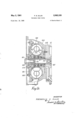
- Figurel shows a vertical longitudinal section with theuexception of the lower half of the epicyclic gearing which is a section on the line 1--1"n Figure 2;
- Figure lA shows a torque converter for the clutch shaft
- Figure 2 shows a transverse sectional elevation on the line 2.-2 in Figure 1;
- Figure 3 shows a vertical sectiony on the liney 3 ⁇ 3 in gearing to which the improvements constituting the in U. S. patent application Serial No. 663,259, now Patent No.2,943,518.
- This method comprises the use of two masses rotatable with a planetary ygear about a transverse axis ⁇ which is Yrotatable in a plane perpendicular to the common axesof the driving and driven shafts or other elements between which the epicyclic gear ris arranged.
- the two masses are diametrically opposed and balance one another.
- the planet carrier When the planet carrier is rotating, thetwo massesare so subjected to centrifugal force that they tend toY move .into the aforementioned plane and resist strongly any forces tending to'move them out of thisplane. When they ⁇ reach such a speed that ,they overcome ⁇ the resisting forces, the planet lcarrier rotates with the drivingianddriven elements 4giving the direct drive higher speed.; u 's f When the driving torque becomes insufficient torovercome the resisting torque, theA two ymasses are .moved forcibly by the yresisting torque in opposition to centri- ⁇ fugal force towards the position in which they are parallel ⁇ to the laxis of the driving and driven members of the present invention are applied .asv well as their association with ⁇ the driving and drivenelements in a motor vehicle transmission system. i
- the clutch shaft'10 transmits engine rotation to the main driving ,bevel wheel 11 forming the first element of the improved variablespeed gearing located within the casing 12'.
- One end of the casing 12 is bolted kto, ⁇ the rear closure 104 of the usual clutch housing 100, the forward end of which is bolted to the engine crankcase (not shown).
- the clutch housing may, for example, enclose a clutch, automatic or otherwise, or a hydro kinetic torque converter of known type as shown in Fig. 1A, to elfect the connection or disconnection of the driving bevel wheel 11 from the crankshaft 102 of an engine or from the output shaft of any other prime mover.
- the bevel wheel 11 is splined to the clutch shaft 10 which may thus bebraked without stalling the engine.
- the clutch shaft 10 is supported in a spigot beading 101 in the rear end ofthe engine crankshaft 102 and by ayball bearing 103 supported by the rear closure 104.
- the "rotatable casing 108' of the converter is driven through bolts 154 from a driving plate 155 secured by bolts 175 to the crankshaft '-102.
- the converter employs two rotatable vane elements 112, 113 and one vane element or stator 114 carried on a one-way brake element 11,5 connected by splines to a nonrotatable sleeve V
- the 'front end of the inal shaft 16 is supported inthe casing ⁇ 13 by :a ball bearing 32.
- the front end of an intermediate shaft 17 is rotatably ⁇ supported lby a ⁇ spigot bearing 14 in the rear end of the clutch shaft 10.
- the other end of the intermediate shaft is supported from the final driven'shaft 16 by means of a spigot bearing 14.
- the main driving bevel wheel 11 meshes withY the rst or outer bevel planet pinions 21, in the present construction two, arranged to ⁇ balance about the central longitudinal axis of the clutch shaft and of the intermediate and'tinal driven shafts 17, 16.
- Each planet pinion 21 is connected to a second or inner planet pinion 22, the connection including a pin 18 and av clamping plate 19.
- the two connected'pinions are carried by roller bearings 23 on a spindle 24 atrightf opposed groups of planet pinions 21, 22' are employed in this condition.
- the smaller'planet pinions 22 mesh with a forward bevel wheel 27 splined on the intermediate shaft 17.
- the hub 44 of the planet carrier 25 is connected by arms 33A to a brake drum 34 or other braking element which is connected rigidly yby splines or otherwise to a sleeve 35.
- the planet' carrier 25, the brake drum 34 and the sleeve 35 thus rotate as a whole and are supported at the front endby bearing rollers 26 on the intermediate shaft 17 and at the rear end by a ball bearing36 having its outer Arace'mounted in the casing 12.v
- the planet'carrier assemblyV may be held against rotation in either direction by a brake'band 37 applied to the drum 34 orby equivalent braking means.
- the planet carrier may be held against backward rotation by a one-way, brake 38 interposed between the sleeve 35 ⁇ and a fixed ring 39 connected by bolts 42 to the rear end of the casing 12. ⁇
- a one-way, brake 38 interposed between the sleeve 35 ⁇ and a fixed ring 39 connected by bolts 42 to the rear end of the casing 12.
- two planet spindles 24 are arranged in line on opposite sides of the hub 44 and the arms 33 are located between them.
- the two speed gearing shown in the drawings is characterized by the provision on each ofthe rst or outer planetary pinions 21 of two masses 43 rotatable with the pinionsl 21, 22.
- the two masseson each planet pinion are balanced about the axes of the spindle 24"of the carrier.
- the forward bevel wheel 27 is driven forwardly by the main driving bevel wheel 11 at either, a low speed when the planet carrier 25 is held against backward rotation by the one-way brake 38, or at a high speed when the carrier is rotated forwardly with the bevel wheels 11, 27.
- The'balanced masses 43' are inoperative at the low speed.
- the two masses 43 on each planet pinion 21 exert suldcient forceto stop rotation ofthe masses and pinions 2.1,V 22 about the carrier spindles 24 so that the gear wheels and planet pinions all rotate only about the axis of the shaft 17.
- the low speed ratio depends upon the difference between the speed ratios of (l) the driving bevel wheel 11 and the outer planet pinion 21 and (2)- the inner planet pinion 22 and the forward bevel wheel 27.'
- the rst ratio is unity andthe second or low speed ratio is 1 :l:7. This is shown in Figure 1 by the difference between the conical angle of pitch surface of the outer gears 21, 11, namely 45, and that of the inner gears 22, 27.
- the masses. 43 have a suitable value in relation to the dimensions of the gearing, a lsmooth transfer from one speed to the other will b e obtained.
- Thepresent invention vhasr forl its object to modify the two-speed gear disclosed inlthe aforementioned prior applications so as to provide a reverse drive anda neutral adjustment since the .original mechanism provided'only 4 has two forward speeds giving a smooth transfer from one speed to the other. l
- the single driven shaft is replaced by the intermediate shaft 17 and the final driven shaft 16.
- a reverse bevel wheel 45 is provided together with means for connecting the driven shaft 16 to either the forward bevel wheel 27 or the reverse bevel wheel 45.
- the two bevel wheels 27, 45 are provided together with means for connecting the driven shaft 16 to either the forward bevel wheel 27 or the reverse bevel wheel 45.
- the planet carrier is held by 4the one-way brake 38 or by the brake drum 34 against backward rotation.
- the carrier brake drum 34 may be held by application of its brake ⁇ band or other braking element for drive gear range to 'become operative.
- the drum may be released and the one-way brake 38 then allows an upward direct
- the change of gear is effected semi-automatically by a small change inthe rate of rotation of the gears, for example, by retardation resulting from va momentary part closing of the throttlewhen the accelerated pedal is momentarily raised. If vthe brake band is not applied, reverse rotation ofthe planet carrier is prevented by the oneway brake 38 only so that the gear will be changed upwards upon any lifting of the accelerator pedal wheneverthedrivingconditions are suitable.
- TheV means for coupling the final driven shaft 16 to either the forward bevel wheel 27 or the reverse bevel wheel will now be described, there being an intermediate or neutral position between the two adjustments.
- This operation is eiected by an internally splined t eter which is interposed between the inner race of the ballbearing 32 and the forward end of the driven shaft 16, the sleeve being permanently connected to the shaft by splines 49.
- Splines 50 separated from the similar splines 49, are provided insidethe ring 47 and are adapted when adjusted forwardly, to engage corresponding splines 52, onl av circular. tting 54 connected to the rear end of the reverse gear shaft 46 when the ring 47 is adjusted rearwardly.v
- the splines S0 similarly engage splines 53 on a Ycircular fitting 55 connected to the intermediate shaft 17. Forward adjustment of the sleeve 47 thus engages the reverse gear while rearward adjustment engages the forward gear.
- The' actuating ring 47 is connected to the selector lever 59. by a selector fork 57 slidable on a selector rod 58 ⁇ fixed-'in the casing 13.
- the fork engagesv a concentricshoulder 56 on the ring 47, and the spherical orcylindrical lower end 60 of the selector lever 59 engages a recess in the fork 57.
- the -actuating lever is formed with a ball 61 which is mounted in acylindrical shell 65 between a fixed upper socket 62 and a lower socket 63 loaded by a spring 64.
- the handle or knob 66 on the upper end of the lever 59 enablesthe driver of a vehicle to adjust the lever forwardly to vengage the forward low gear and rearwardly to engagethe reverse gear having the same reduction ratio as the lower forward gear.
- the gear lever and parts actuated' thereby are held in the forward, neutral or reverse positions by a spring operated ball and detent type lock on the selector rod S8.
- This action may be brought about by applying a brake band 76 to the brake drum 77 which rotates with the main driving bevel wheel 11.
- This operation is brought about by a small amount of downward movement imparted to the handle 66 when the mechanism is actuated for a reverse or forward gear engagement.
- the handle 66 is held in its raised position by a spring 64, but may be pressed downwards to a very limited extent so as to actuate a valve 79 controlling the supply of fluid under pressure to the brake band 76 on the reversing brake drum 77.
- a block 80 provided with an inlet conduit 81 connected to a source of uid under pressure and an outlet conduit 82 leading to an operating cylinder for the brake band 76 encircling the reversing drum 77.
- the valve 79 between these two conduits is opened by the small downward movement of the handle 66 previously referred to.
- the valve is normally held in its upward position by a helical spring 84 so that its conical end engages a seat closing the connection 83 to the inlet conduit 81.
- the valve is pressed downwards by the handle 66 through the medium of a leaf spring 86.
- One end o-f the spring is actuated by downward movement of the downward extension 87 from the part-spherical socket 63 on which the ball 61 of the handle bears.
- the lower edge of this extension 87 engages the free end of the spring 86, the other end of which acts as a fulcrum.
- the spring ⁇ 86 is normally raised to its uppermost position by the spring 84 acting on the small valve 79, the connection between the two being formed by a circlip 88 on the lower end of the stem 89 of the valve.
- the valve 83 moves downwards sufficiently to open the upper conduit and connect it to the lower conduit, while escape of uid under pressure is prevented by the lower conical end of the valve engaging the lower seating.
- Two separate masses 43 may be used as described, each secured by set bolts or the like to the outer planet Vpinion 21.
- a single metal disc is machined to the shape shown in Figure 4 and mounted as shown in Figures l and 2, to provide the equivalent of two separated balanced masses and thus obtain the same result in a simpler and more effective manner.
- a rotary pump 67 actuated from the final driven shaft 16. draws oil from the sump through a conduit 68 and forces the oil under pressure to the several parts requlrlng lubrication through passages 69 in the shafts.
- Two speed forward and reverse epicyclic gearing Y comprising in combination: co-axial driving, driven and ⁇ intermediate shafts; a main driving bevel wheel'on the driving shaft. and a smaller co-axial forward bevel wheel f 6 on the intermediate shaft; an outer planet bevel pinion meshing with said main driving bevel wheel; a vsmaller inner planet bevel pinion meshing with said forward bevel wheel, both of said bevel pinions' being connected so as to rotate together; a planet carrierhavingv a transverse spindle upon which the said bevel pinions are mounted; -a one-way brake preventing backward rotation of Ithe planet carrier; two balanced masses securedt'o'the planet bevel pinions whereby changes between the forward transmission ratios may be carried out automatically; a reverse bevel wheel meshing with the inner bevel pinion on the side thereof opposite to theforward bevel wheel; two toothed clutch members each rotatable with a rearward extension from the forward and the reverse bevel wheels, respectively; a cooper
- Forward and reverse gearing comprising, in combination: a fixed casing; co-axial driving, driven, and
- intermediate shafts mounted in said casing for rotation with respect to each other and to the casing; a main dniving bevel wheel on the driving shaft, and a smaller forward bevel wheel on the intermediate shaft; an outer planet bevel pinion meshing with said main driving wheel, and a smaller inner planet bevel pinion meshing with said forward bevel wheel, said bevel pinions being connected so as to rotate together; a planet carrier rotatably mounted on said intermediate shaft and having a spindle upon which the said bevel pinions are rotatably mounted; a reverse bevel wheel rotatably mounted and meshing with the inner bevel pinion onpthe side thereof opposite to the forward bevel wheel; a one-way brake connected between said carrier and the casing and preventing backward rotation o-f the planet carrier; centrifugally operated means on the carrier operative to effectively rigidly connect the main drivingbevel wheel and the forward bevel wheel to one another to give a high speed forward drive and when inoperative enabling a low speed indirect forward drive to become operative through the
- Gearing according to claim 2 comprising an internally splined ring movable by the actuating lever, the clutch members rotatable with the forward bevel wheel, the reverse bevel wheel and the nal driven shaft being splined and located adjacent one another axially to enable the internally splined ring to mesh with the splined clutch members and thereby to selectively connect the forward and reverse bevel wheels rotatably with the said driven shaft.
- Gearing according to claim 2 comprising a braking element connected rigidly to the planet carrier, a sleeve splined thereto and connected to the rotatable member of the one way brake, the reverse bevel gear being rotatably supported by said sleeve and located between the planet carrier and said braking element.
- Gearing according to claim 2 comprising a braking element connected rigidly to the planet carrier and to the rotatable member of the one way brake, the carrier being held ⁇ against rotation in either direction when the brake is applied thereby to maintain the low gear in operation thus overriding the centrifugally operated means.
Landscapes
- Engineering & Computer Science (AREA)
- General Engineering & Computer Science (AREA)
- Mechanical Engineering (AREA)
- Structure Of Transmissions (AREA)
Description
May 2, 1961 F. ET ELUS 2,982,155
VARIABLE GEAR UNITSl Filed Dec. 19, 1958 FREDERI'CK E. E1. Li s ATTORNEYS 4 Sheets-Sheet 1 May 2, 15/61 F. E. ELUS 2,982,155 VARIABLE GEAR UNITS v Filed Dec. 19, 1958 4 Sheets-Sheet 2 774 HHHH HION 120 m 19 T TRNE YS May 2, 196,1 F. E. ELLIS VARIABLE GEAR UNITS 4 Sheets-Sheet 3 Filed DGO. 19, 1958 A -INVENTOR rREDERicK E. ELUS BY y - y ATTORNEYS May 2, 1961 F. E. ELLIS 2,982,155
VARIABLE GEARUNITS Filed Dec. 19, 1958 4`Sheets-Sheet 4 INVENTOR FREnERicK E. EL/ s ATTORNEYS United States Patent() Y 2,982,155 i` VARIABLE GEAR UNITS Frederick E. Ellis, Tachbrook Mallory, near Leamington Spa, England, assigner to Automotive 'Products 1Company Limited, Leamington Spa, England, a British company, and Hugh C." Reid, Belfast, 2Northernlleland Filed Dec. 19, 1958, SienNo. 781,696 e claims prierify, application Great Britain Dec. 30, r195'/ sciaifs;V (ci. 'I4-752) This invention relates .to two-speed forwarda'nd reverse epicyclic gearing in which a main driving bevel wheel anda smaller coaxial forward hevelwheel mesh respectively with Ian .outer planet bevel pinion and Van inner. smallerA bevel pinion. VVThe two gear ratios are different, both pinions being rotatable together about a carrier aXisbeing rotatableonly in a forward direction in a plane perpendicular to theV common axis of the main driving andforward bevel wheels. Means is provided tor preventingrotation of the planetpinions aboutthe'ii axes thus giving` a direct. drive, or'for allowing such rotation but Apreventing backward rotation Hof the planet carrier thus giving a. drive through the `gearing at a different transmission ratio. A reverse bevel wheel coaxialwith the. forward bevel wheel `meshes with the inner planetary. pinion ontheside thereof opposite to the forwardbevel wheel and means is provided for connecting a final rotatable driven shaft or like-driven member to theforward or to the reverse bevel wheel.'
In this kind of gearing, itis necessary Yto make'provision for preventing rotation -of the planet pinions about their axes thus giving a direct `drive or for allowing such rotation but .preventing backward.V rotation of Ythe planet carrier r thus giving a drive through ,the gearing` at a different transmissionratio.
Patented May 2, 1961 ice ., tardation resulting, for example, from the momentary 20, transverse airis ofa planet carrier -spindle with the said closing of the throttle or otherwise.
Improvements in this kind if gearing have also been disclosed in the co-pending application Serial No. 800,-
. 457 in which a friction or other clutch when operative connects the main dn'ving bevel wheel and the forward bevel wheel to one another to give a direct high ratio drive. The clutch when inoperative lenabling an indirect drive through the gearing to become operative, and the planet carrier lis then held against backward rotation.
The principal object of the invention is to ensure that the forward and reverse gear changes are brought about without shock or noise.
A further object is to provide a compact assembly of mechanism whereby the several automatic and other controlling operations may be carried out with a minimum movement, effort or thought by the driver of the vehicle tokwhich gear is applied.
VIn the embodiment of the invention shown by way of example in Ithe accompanying drawings:
Figurel shows a vertical longitudinal section with theuexception of the lower half of the epicyclic gearing which is a section on the line 1--1"n Figure 2;
. Figure lA shows a torque converter for the clutch shaft; Y
Figure 2 shows a transverse sectional elevation on the line 2.-2 in Figure 1;
Figure 3 shows a vertical sectiony on the liney 3`3 in gearing to which the improvements constituting the in U. S. patent application Serial No. 663,259, now Patent No.2,943,518. This method comprises the use of two masses rotatable with a planetary ygear about a transverse axis `which is Yrotatable in a plane perpendicular to the common axesof the driving and driven shafts or other elements between which the epicyclic gear ris arranged. The two masses are diametrically opposed and balance one another. When the planet carrier is rotating, thetwo massesare so subjected to centrifugal force that they tend toY move .into the aforementioned plane and resist strongly any forces tending to'move them out of thisplane. When they `reach such a speed that ,they overcome `the resisting forces, the planet lcarrier rotates with the drivingianddriven elements 4giving the direct drive higher speed.; u 's f When the driving torque becomes insufficient torovercome the resisting torque, theA two ymasses are .moved forcibly by the yresisting torque in opposition to centri- `fugal force towards the position in which they are parallel `to the laxis of the driving and driven members of the present invention are applied .asv well as their association with `the driving and drivenelements in a motor vehicle transmission system. i
'I `he usual clutch shaft'10 transmits engine rotation to the main driving ,bevel wheel 11 forming the first element of the improved variablespeed gearing located within the casing 12'. One end of the casing 12 is bolted kto, `the rear closure 104 of the usual clutch housing 100, the forward end of which is bolted to the engine crankcase (not shown). The clutch housing may, for example, enclose a clutch, automatic or otherwise, or a hydro kinetic torque converter of known type as shown in Fig. 1A, to elfect the connection or disconnection of the driving bevel wheel 11 from the crankshaft 102 of an engine or from the output shaft of any other prime mover. The bevel wheel 11 is splined to the clutch shaft 10 which may thus bebraked without stalling the engine. The clutch shaft 10 is supported in a spigot beading 101 in the rear end ofthe engine crankshaft 102 and by ayball bearing 103 supported by the rear closure 104. The "rotatable casing 108' of the converter is driven through bolts 154 from a driving plate 155 secured by bolts 175 to the crankshaft '-102. The converter employs two rotatable vane elements 112, 113 and one vane element or stator 114 carried on a one-way brake element 11,5 connected by splines to a nonrotatable sleeve VThe 'front end of the inal shaft 16 is supported inthe casing `13 by :a ball bearing 32. The front end of an intermediate shaft 17 is rotatably `supported lby a` spigot bearing 14 in the rear end of the clutch shaft 10. The other end of the intermediate shaft is supported from the final driven'shaft 16 by means of a spigot bearing 14.
In the two speed gearing forming the subject of the aforementioned patent applications, as utilised in the present application, the main driving bevel wheel 11 meshes withY the rst or outer bevel planet pinions 21, in the present construction two, arranged to `balance about the central longitudinal axis of the clutch shaft and of the intermediate and'tinal driven shafts 17, 16.
Each planet pinion 21 is connected to a second or inner planet pinion 22, the connection including a pin 18 and av clamping plate 19. The two connected'pinions are carried by roller bearings 23 on a spindle 24 atrightf opposed groups of planet pinions 21, 22' are employed in this condition.
The smaller'planet pinions 22 mesh with a forward bevel wheel 27 splined on the intermediate shaft 17.
The hub 44 of the planet carrier 25 is connected by arms 33A to a brake drum 34 or other braking element which is connected rigidly yby splines or otherwise to a sleeve 35. The planet' carrier 25, the brake drum 34 and the sleeve 35 thus rotate as a whole and are supported at the front endby bearing rollers 26 on the intermediate shaft 17 and at the rear end by a ball bearing36 having its outer Arace'mounted in the casing 12.v The planet'carrier assemblyV may be held against rotation in either direction by a brake'band 37 applied to the drum 34 orby equivalent braking means. Alternatively, the planet carrier may be held against backward rotation by a one-way, brake 38 interposed between the sleeve 35` and a fixed ring 39 connected by bolts 42 to the rear end of the casing 12.` In they arrangementshown, two planet spindles 24 are arranged in line on opposite sides of the hub 44 and the arms 33 are located between them.
The two speed gearing shown in the drawings is characterized by the provision on each ofthe rst or outer planetary pinions 21 of two masses 43 rotatable with the pinionsl 21, 22. The two masseson each planet pinion are balanced about the axes of the spindle 24"of the carrier. v'
The forward bevel wheel 27 is driven forwardly by the main driving bevel wheel 11 at either, a low speed when the planet carrier 25 is held against backward rotation by the one-way brake 38, or at a high speed when the carrier is rotated forwardly with the bevel wheels 11, 27. The'balanced masses 43'are inoperative at the low speed. As the speed of rotation'of the planet carrier increases to a predetermined value, the two masses 43 on each planet pinion 21 exert suldcient forceto stop rotation ofthe masses and pinions 2.1,V 22 about the carrier spindles 24 so that the gear wheels and planet pinions all rotate only about the axis of the shaft 17.
This gives the higher direct speed ratio.
The low speed ratio depends upon the difference between the speed ratios of (l) the driving bevel wheel 11 and the outer planet pinion 21 and (2)- the inner planet pinion 22 and the forward bevel wheel 27.' In the `constructionshown the rst ratio is unity andthe second or low speed ratio is 1 :l:7. This is shown in Figure 1 by the difference between the conical angle of pitch surface of the outer gears 21, 11, namely 45, and that of the inner gears 22, 27.
Provided that the masses. 43 have a suitable value in relation to the dimensions of the gearing, a lsmooth transfer from one speed to the other will b e obtained.
Thepresent invention vhasr forl its object to modify the two-speed gear disclosed inlthe aforementioned prior applications so as to provide a reverse drive anda neutral adjustment since the .original mechanism provided'only 4 has two forward speeds giving a smooth transfer from one speed to the other. l
In the present invention the single driven shaft is replaced by the intermediate shaft 17 and the final driven shaft 16. Also, a reverse bevel wheel 45 is provided together with means for connecting the driven shaft 16 to either the forward bevel wheel 27 or the reverse bevel wheel 45. The two bevel wheels 27, 45
rotate` oppositely since they mesh with opposite sides 41a within the sleeve 35.
During forward low gear running or reverse gear running, the planet carrier is held by 4the one-way brake 38 or by the brake drum 34 against backward rotation.
The carrier brake drum 34 may be held by application of its brake` band or other braking element for drive gear range to 'become operative.
vehicle speeds up to, for example, 25 miles per hour,
so that'the vehicle is held in low gear whether the driving conditions are suitable or unsuitable for an upward change. Above this speed, the drum may be released and the one-way brake 38 then allows an upward direct The change of gear is effected semi-automatically by a small change inthe rate of rotation of the gears, for example, by retardation resulting from va momentary part closing of the throttlewhen the accelerated pedal is momentarily raised. If vthe brake band is not applied, reverse rotation ofthe planet carrier is prevented by the oneway brake 38 only so that the gear will be changed upwards upon any lifting of the accelerator pedal wheneverthedrivingconditions are suitable.
TheV means for coupling the final driven shaft 16 to either the forward bevel wheel 27 or the reverse bevel wheel will now be described, there being an intermediate or neutral position between the two adjustments.
This operation is eiected by an internally splined t eter which is interposed between the inner race of the ballbearing 32 and the forward end of the driven shaft 16, the sleeve being permanently connected to the shaft by splines 49.
Splines 50, separated from the similar splines 49, are provided insidethe ring 47 and are adapted when adjusted forwardly, to engage corresponding splines 52, onl av circular. tting 54 connected to the rear end of the reverse gear shaft 46 when the ring 47 is adjusted rearwardly.v The splines S0 similarly engage splines 53 on a Ycircular fitting 55 connected to the intermediate shaft 17. Forward adjustment of the sleeve 47 thus engages the reverse gear while rearward adjustment engages the forward gear.
The' actuating ring 47 is connected to the selector lever 59. by a selector fork 57 slidable on a selector rod 58` fixed-'in the casing 13. The fork engagesv a concentricshoulder 56 on the ring 47, and the spherical orcylindrical lower end 60 of the selector lever 59 engages a recess in the fork 57. v
' ,The -actuating lever is formed with a ball 61 which is mounted in acylindrical shell 65 between a fixed upper socket 62 and a lower socket 63 loaded by a spring 64.
YThe handle or knob 66 on the upper end of the lever 59 enablesthe driver of a vehicle to adjust the lever forwardly to vengage the forward low gear and rearwardly to engagethe reverse gear having the same reduction ratio as the lower forward gear. The gear lever and parts actuated' thereby are held in the forward, neutral or reverse positions by a spring operated ball and detent type lock on the selector rod S8.
When carrying out, the reversing operation it is essential that the two splined circular fittings 54 and 55 aesawzs should both be brought to rest before the actuating ring i 47 isv moved in either direction to engage one or *the` other according Nto Whether the change is to be Vmade from a forward drive to a reverse drive or vice versa. These two members 54, '5 are connected respectively to' the. reverse gear wheel 45 and the forward gear wheel 27. When the car comes to rest, the splined fitting 48 and the iinal drive shaft 16 no longer rotate, but the two fittings 54 and 55 will rotate in opposite directions due to the planetary pinion 21 being driven by the main driving bevel wheel 11 from theclutch shaft 10. In order to bring these two splined members 54, `55 to rest itis necessary to stop the rotation of the main driving bevel wheel 11'and the clutch shaft 10 torwhich it is splined. This incidentally n brings the driven member of the hydro kinetic torque Y converter (not shown) connected to the clutch shaft 10 to rest.` l
This action may be brought about by applying a brake band 76 to the brake drum 77 which rotates with the main driving bevel wheel 11. This operation is brought about by a small amount of downward movement imparted to the handle 66 when the mechanism is actuated for a reverse or forward gear engagement. As described previously in connection with Figures 1 and 3 of the drawings, the handle 66 is held in its raised position by a spring 64, but may be pressed downwards to a very limited extent so as to actuate a valve 79 controlling the supply of fluid under pressure to the brake band 76 on the reversing brake drum 77.
Referring particularly to Figure 3, there is attached to the side of the shell 65 on the casing 13` a block 80 provided with an inlet conduit 81 connected to a source of uid under pressure and an outlet conduit 82 leading to an operating cylinder for the brake band 76 encircling the reversing drum 77. The valve 79 between these two conduits is opened by the small downward movement of the handle 66 previously referred to. The valve is normally held in its upward position by a helical spring 84 so that its conical end engages a seat closing the connection 83 to the inlet conduit 81. The valve is pressed downwards by the handle 66 through the medium of a leaf spring 86. One end o-f the spring is actuated by downward movement of the downward extension 87 from the part-spherical socket 63 on which the ball 61 of the handle bears. The lower edge of this extension 87 engages the free end of the spring 86, the other end of which acts as a fulcrum. The spring`86 is normally raised to its uppermost position by the spring 84 acting on the small valve 79, the connection between the two being formed by a circlip 88 on the lower end of the stem 89 of the valve. When the handle is depressed, the valve 83 moves downwards sufficiently to open the upper conduit and connect it to the lower conduit, while escape of uid under pressure is prevented by the lower conical end of the valve engaging the lower seating. As soon as the handle is released it is raised by the spring 64 so that the valve 83 opens the lower conduit and closes the upper conduit. The extensions of the inlet and outlet conduits 81, 82 to a pressure pump and to the brake 0perating means are not shown.
Two separate masses 43 may be used as described, each secured by set bolts or the like to the outer planet Vpinion 21. Preferably a single metal disc is machined to the shape shown in Figure 4 and mounted as shown in Figures l and 2, to provide the equivalent of two separated balanced masses and thus obtain the same result in a simpler and more effective manner.
A rotary pump 67 actuated from the final driven shaft 16. draws oil from the sump through a conduit 68 and forces the oil under pressure to the several parts requlrlng lubrication through passages 69 in the shafts.
What is claimed is:
l. Two speed forward and reverse epicyclic gearing Y comprising in combination: co-axial driving, driven and `intermediate shafts; a main driving bevel wheel'on the driving shaft. and a smaller co-axial forward bevel wheel f 6 on the intermediate shaft; an outer planet bevel pinion meshing with said main driving bevel wheel; a vsmaller inner planet bevel pinion meshing with said forward bevel wheel, both of said bevel pinions' being connected so as to rotate together; a planet carrierhavingv a transverse spindle upon which the said bevel pinions are mounted; -a one-way brake preventing backward rotation of Ithe planet carrier; two balanced masses securedt'o'the planet bevel pinions whereby changes between the forward transmission ratios may be carried out automatically; a reverse bevel wheel meshing with the inner bevel pinion on the side thereof opposite to theforward bevel wheel; two toothed clutch members each rotatable with a rearward extension from the forward and the reverse bevel wheels, respectively; a cooperating clutchy member on the driven shaft;` a selector lever for actuating said clutch members so as to engage the forward wheeljorthe Vreverse wheel; a brake drum rotatable with the main driving bevel wheel; means Ifor adjusting the selector lever in a direction transverse to the gear selecting movement when the driven shaft is stationary so as to apply a braking element to said brake drum and thus bring the said toothed clutch members to rest whereby, in the said combination, the forward gear changes may be made automatically and without shock and the forward and reverse gear changes may be made without shock.
2. Forward and reverse gearing comprising, in combination: a fixed casing; co-axial driving, driven, and
intermediate shafts mounted in said casing for rotation with respect to each other and to the casing; a main dniving bevel wheel on the driving shaft, and a smaller forward bevel wheel on the intermediate shaft; an outer planet bevel pinion meshing with said main driving wheel, and a smaller inner planet bevel pinion meshing with said forward bevel wheel, said bevel pinions being connected so as to rotate together; a planet carrier rotatably mounted on said intermediate shaft and having a spindle upon which the said bevel pinions are rotatably mounted; a reverse bevel wheel rotatably mounted and meshing with the inner bevel pinion onpthe side thereof opposite to the forward bevel wheel; a one-way brake connected between said carrier and the casing and preventing backward rotation o-f the planet carrier; centrifugally operated means on the carrier operative to effectively rigidly connect the main drivingbevel wheel and the forward bevel wheel to one another to give a high speed forward drive and when inoperative enabling a low speed indirect forward drive to become operative through the gearing connection from the main driving bevel wheel through theV planet pinions to the forward bevel wheel and the reverse bevel wheel; toothed clutch members connected to the forward and the reverse bevel wheels respectively; a clutch member on the driven shaft selectively cooperable with each of said clutch members; a selector lever actuating said cooperable clutch member so as to selectively engage the clutch members of the forward gear and the reverse gear; a brake drum rotatable with the main driving bevel wheel, a braking element; means controlled by the selector lever to lapply the braking element to said brake drum and thus bring the said toothed clutch members to rest, whereby the forward and reverse gear changes may be effected without shock.
3. Gearing according to claim 2 comprising an internally splined ring movable by the actuating lever, the clutch members rotatable with the forward bevel wheel, the reverse bevel wheel and the nal driven shaft being splined and located adjacent one another axially to enable the internally splined ring to mesh with the splined clutch members and thereby to selectively connect the forward and reverse bevel wheels rotatably with the said driven shaft.
4. Gearing according to claim 3, in which the forward bevel wheel and the corresponding splined clutch member are secured to opposite ends of the intermedi-ate shaft and the reverse bevel wheel is connected to the corresponding splined clutch member by a tubular shaft.
, 5'. Gearing according to claim 3, in which said internally splined ring is operated axially by'the selector lever Vand the splined clutch members of the bevel wheels are spaced apart a distance greater than the length of the splines on -the splined ring so as to render the actuating ring selectively adjustable into forward, neutral, and reverse driving positions.
6. Gearing according to claim 2 comprising a braking element connected rigidly to the planet carrier, a sleeve splined thereto and connected to the rotatable member of the one way brake, the reverse bevel gear being rotatably supported by said sleeve and located between the planet carrier and said braking element.
7. Gearing according to claim 2 wherein the driving shaft supports and drives the main driving bevel wheel, the intermediate shaft to which the forward bevel wheel is connected being supported bythe saiddriving shaft and by the driven shaft.
' 8. Gearing according to claim 2, comprising a braking element connected rigidly to the planet carrier and to the rotatable member of the one way brake, the carrier being held `against rotation in either direction when the brake is applied thereby to maintain the low gear in operation thus overriding the centrifugally operated means.
References Cited in the file of this partent UNITED STATES PATENTS 1,039,743 Holliday oct. 1, 1912 1,610,284 Hime Dec. 14, 1926 2,247,578 Giraud etal. July 1, 1941 FOREIGN PATENTS 692,079 France Oct. 30, 1930
Applications Claiming Priority (1)
| Application Number | Priority Date | Filing Date | Title |
|---|---|---|---|
| GB2982155X | 1957-12-30 |
Publications (1)
| Publication Number | Publication Date |
|---|---|
| US2982155A true US2982155A (en) | 1961-05-02 |
Family
ID=10919086
Family Applications (1)
| Application Number | Title | Priority Date | Filing Date |
|---|---|---|---|
| US781696A Expired - Lifetime US2982155A (en) | 1957-12-30 | 1958-12-19 | Variable gear units |
Country Status (1)
| Country | Link |
|---|---|
| US (1) | US2982155A (en) |
Cited By (2)
| Publication number | Priority date | Publication date | Assignee | Title |
|---|---|---|---|---|
| US3164035A (en) * | 1961-03-27 | 1965-01-05 | Automotive Prod Co Ltd | Power transmission systems providing automatic changes of gear ratio |
| US3183742A (en) * | 1961-04-14 | 1965-05-18 | Automotive Prod Co Ltd | Power transmission systems providing automatic changes of gear ratio |
Citations (4)
| Publication number | Priority date | Publication date | Assignee | Title |
|---|---|---|---|---|
| US1039743A (en) * | 1910-04-30 | 1912-10-01 | Edgar Percy Holliday | Change-speed gearing. |
| US1610284A (en) * | 1926-12-14 | And owe-half to | ||
| FR692079A (en) * | 1929-05-18 | 1930-10-30 | Dynamic shifting | |
| US2247578A (en) * | 1940-02-21 | 1941-07-01 | Giroud Francisco Felipe Lazaga | Differential transmission |
-
1958
- 1958-12-19 US US781696A patent/US2982155A/en not_active Expired - Lifetime
Patent Citations (4)
| Publication number | Priority date | Publication date | Assignee | Title |
|---|---|---|---|---|
| US1610284A (en) * | 1926-12-14 | And owe-half to | ||
| US1039743A (en) * | 1910-04-30 | 1912-10-01 | Edgar Percy Holliday | Change-speed gearing. |
| FR692079A (en) * | 1929-05-18 | 1930-10-30 | Dynamic shifting | |
| US2247578A (en) * | 1940-02-21 | 1941-07-01 | Giroud Francisco Felipe Lazaga | Differential transmission |
Cited By (2)
| Publication number | Priority date | Publication date | Assignee | Title |
|---|---|---|---|---|
| US3164035A (en) * | 1961-03-27 | 1965-01-05 | Automotive Prod Co Ltd | Power transmission systems providing automatic changes of gear ratio |
| US3183742A (en) * | 1961-04-14 | 1965-05-18 | Automotive Prod Co Ltd | Power transmission systems providing automatic changes of gear ratio |
Similar Documents
| Publication | Publication Date | Title |
|---|---|---|
| US2748623A (en) | Orbit gear controlled reversible planetary transmissions | |
| US3006206A (en) | Infinitely variable ratio transmission | |
| US3545302A (en) | Vehicle transmission systems | |
| US2348763A (en) | Power transmission | |
| US2730914A (en) | Multi-speed planetary vehicle drive mechanism | |
| US2190831A (en) | Transmission | |
| US2377009A (en) | Automatic power transmission | |
| US2445573A (en) | Transmission | |
| US2247714A (en) | Transmission mechanism | |
| US2530200A (en) | Transmission | |
| US2704468A (en) | Power transmission | |
| US2319388A (en) | Hydromechanical transmission gearing | |
| US2127655A (en) | Planetary transmission | |
| US2982155A (en) | Variable gear units | |
| US3548682A (en) | Vehicle transmission systems | |
| US3728911A (en) | Infinitely variable speed transmissions | |
| US2359423A (en) | Hydraulic transmission | |
| US2159427A (en) | Power transmission | |
| US2149320A (en) | Variable ratio transmission | |
| US2997898A (en) | Automatic transmission of power | |
| US1988440A (en) | Automatic automotive transmission gearing | |
| US2772583A (en) | Transmissions | |
| US2891421A (en) | Automatic transmission for automotive vehicles | |
| US3164035A (en) | Power transmission systems providing automatic changes of gear ratio | |
| US3327565A (en) | Automatic transmission for automotive vehicles |