US2982548A - Apparatus for separating objects such as bowling balls and pins - Google Patents
Apparatus for separating objects such as bowling balls and pins Download PDFInfo
- Publication number
- US2982548A US2982548A US834841A US83484159A US2982548A US 2982548 A US2982548 A US 2982548A US 834841 A US834841 A US 834841A US 83484159 A US83484159 A US 83484159A US 2982548 A US2982548 A US 2982548A
- Authority
- US
- United States
- Prior art keywords
- gate
- ball
- pins
- pin
- conveyor
- Prior art date
- Legal status (The legal status is an assumption and is not a legal conclusion. Google has not performed a legal analysis and makes no representation as to the accuracy of the status listed.)
- Expired - Lifetime
Links
- 238000000926 separation method Methods 0.000 description 4
- 230000005484 gravity Effects 0.000 description 2
- 230000008878 coupling Effects 0.000 description 1
- 238000010168 coupling process Methods 0.000 description 1
- 238000005859 coupling reaction Methods 0.000 description 1
- 230000001419 dependent effect Effects 0.000 description 1
- 230000000977 initiatory effect Effects 0.000 description 1
- 239000000696 magnetic material Substances 0.000 description 1
- 230000000704 physical effect Effects 0.000 description 1
- 230000000284 resting effect Effects 0.000 description 1
Images

Classifications
-
- A—HUMAN NECESSITIES
- A63—SPORTS; GAMES; AMUSEMENTS
- A63D—BOWLING GAMES, e.g. SKITTLES, BOCCE OR BOWLS; INSTALLATIONS THEREFOR; BAGATELLE OR SIMILAR GAMES; BILLIARDS
- A63D5/00—Accessories for bowling-alleys or table alleys
- A63D5/02—Apparatus for trapping or lifting the balls; Separate devices for returning the balls
- A63D5/023—Separate devices for returning the balls
Definitions
- KRACHT ET AL 2,982,548 APPARATUS FOR SEPARATING OBJECTS SUCH AS BOWLING BALLS AND PINS Filed Aug. 19, 1959 2 Sheets-Sheet 1 FIGJ May 2, 1961
- Our invention relates to automatic bowling pin setting machines and more particularly to a device adapted to facilitate the return of bowling balls from the pit end to the player end of the bowling alley.
- the balls and pins are carried laterally of the pin setter machine by a belt conveyor. Separation of the balls from the pins is accomplished by means of a gate mechanism, built into the conveyor, which is opened by the presence of a ball at a predetermined point on the conveyor. Opening of the gate allows the bowling ball to drop from the conveyor to a ball return chute situated directly below thegate. Bowling pins are not capable of operating the gate mechanism.
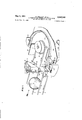
- Fig. 1 illustrates a completely mechanical embodiment of our ball release gate
- Fig. 2 shows a further embodiment which is electrically operated.
- Fig. 1 the invention is shown in conjunction with a horizontal conveyor system comprised of an endless belt having runs 1, 2, 3, and 4 and appropriate belt pulleys, two of which 5, 17, are shown in the drawing.
- Belt runs 2 and 3 move in the direction, left to right in the drawings, as indicated by the arrows associated therewith.
- Runs 2 and 3 form a parallel belt conveyor while 1 and 4 are the return runs of the endless belt.
- Runs 2 and 3 are so spaced and tensioned as to support thereon a ball 11 as shown or a bowling pin in its inverted position.
- the belts support the pin by contact with the encircling rubber band or ring.
- Belt runs 2, 3 are so spaced that the head end or top of the pin is allowed to pass through between them and the pin, due to the location of its centre of gravity, rides the conveyor in an inverted position.
- Pins on the conveyor runs 2 and 3 are carried across the pinsetter machine and upon reaching the end of run 3, whereat the belt encircles pulley 5, the pin by virtue of its band resting on run 2 and subsequently rim 18 of pulley 17 is rolled about its vertical axis to follow members 20 and 27 around and into a pin storage magazine comprised by sidewalls 29, 30 and a roller type conveyor utilizing two sets of rollers 28, one on each of members 29, '30. A pin entering the magazine is moved forward (to the left) by the next arriving pin from the horizontal belt conveyor.
- the ball gate mechanism consists of an angular shaped gate member 31 pivoted at its vertex on a shaft member 21.
- tab 22 of gate arm 20 is pressed against pinguiding flange 27 by means of a spring 23 stretched between the outer arm of gate 31 and tab 24 on frame member 26.
- arm 20 forms a continuation of the conveyor as suggested in the preceding paragraph.
- Gate 31 is normally held in its closed position by a locking pin 9 journalled for vertical movement in a bearing 10 which is an integral projection of frame member 8.
- a pin 34 in conjunction with bearing 10 limits the downward movement of lock pin 9.
- Frame member 8 also supports an angled sensing member 14 in a position as shown overriding the horizontal conveyor.
- the sensing member 14 is journalled on pin 15 in frame 8 for pivotal movement about a horizontal axis.
- a substantially horizontal extending arm 33 of angled member 14 is connected by pin 16 to one end of an extensible member 12,'the other end being connected to the top end 'of lock pin 9.
- a length adjusting sleevenut 13 on member 12 allows for the proper position of arm 32 with respect to the conveyor as will be described subsequently.
- Pin 9 is held in its locking position by the combined weights of pin 9, members 12, 13, and the horizontally disposed arm of sensing member 33. If desired, a spring may be employed to bias pin 9 to its locking position.
- a ball return chute 25 is effective to return balls dropped therein to a ball return runway, not shown.
- a ball 11 is carried tranversely lift to right of the machine on conveyor runs 2, 3.
- the arm 32 of member 14 is located slightly on centre of the axis of the conveyor and at a height above suchthat the ball, when passing beneath, contacts arm 32 and moves it further off centre in the direction indicated by the arrow.
- the proper positioning of arm 32 with respect to the conveyor is accomplished by adjustment of the length of member 12 by means of sleeve nut 13.
- the pin end of arm 33 is raised and by virtue of coupling members 16, 13, 12, lock pin 9 is raised to release gate member 31. At this point the weight of the ball on gate 31 is elfective to move the gate laterally against the tension of spring 23.
- Bowling pins in the inverted position, ride low enough on the conveyor so that no contact is made with arm 32 when passing therebeneath and inadvertent dropping of a bowling pin into chute 25 is avoided.
- a gate member 34 when in its closed position as shown is in alignment with belt run 3. Gate 34 is pivoted at 37 to open to the position as shown by the broken lines.
- a solenoid 44 when energized is effective to open gate 34 through the medium of a plunger arm 43, a pivoted member 39 rotatable about pin 40 and a linkage member 38.
- a spring 41 in tension between member 39 and a frame point 42 returns the gate to the closed position when solenoid 44 is de-energized. It should be noted that when the gate 34 is closed, the pivots for linkage 38 and member 39 are in a straight line and consequently gate 34 is locked and can not be opened solely by laterial pressure of a ball or pin thereon.
- the control of unlocking and opening of gate 34 is effected by a sensing member 14 having a ball contact arm 32 and a switch 35 operated by arm 36 in conjunction with a cam on member 14. Movement of arm 32 rotates member 14 about its horizontal pivot point to close switch 35 and apply energy from a battery 45 to energize solenoid 44 through wires 46, 47 and thus move the gate and linkage members to the position shown by the broken lines.
- This system gives a more precise gate opening since the action is not dependent on ball weight.
- a heavy spring 41 may be employed to rapidly return the gate 34 to its closed position which is an advantage when a pin closely follows a ball on the transverse conveyor.
- a bowling ball may be impregnated with magnetic material and a properly positioned magnetic sensing device be employed to unlock the gate and energize the solenoid.
- the combination of the magnetic sensing device and the weightoperated gate of Fig. 1 may be employed.
- photo-electric or dielectric sensing devices may be employed for actuation of the gate.
- the gate mechanism may be pivoted for rotation about a horizontal axis and biased to its closed position by gravity.
- a locking system similar to that shown in Fig. 1 may be employed.
- a conveyor having parallel belt runs spaced to carry balls and pins transversely of said machine, gate means inserted in the conveyor normally presenting a stationary continuance of one of said runs, means locking said gate in its normal position, and ball sensing means,
- a machine as claimed in claim 1' wherein said outward movement of said gate is effected by a solenoid energized by said sensing means.
- sensing means is actuated by a ball dimension greater than a predetermined minimum.
- sensing means is actuated by an electrical property of said ball.
- a pin setting machine means to separate bowling balls from pins comprising, a conveyor having parallel belt runs adapted to carry balls and inverted pins transversely of the machine, an angular gate means pivoted at its vertex for horizontal plane rotation, one arm of said gate forming a stationary continuance of one of said runs in the closed position of said gate, means biasing said gate to its closed position, locking means preventing inadvertent opening of said gate, a ball return chute located below said conveyor in the vicinity of said gate, a ball sensing means located to detect the presence of a ball adjacent said gate and means operated in conjunc, tion with said sensing means to initiate unlocking and opening of said gate to drop a sensed ball to said ball return chute.
- a pin setting machine means to separate bowling balls from pins comprising, a conveyor having parallel belt runs adapted to carry balls and inverted pins transversely of said machine, an angular shaped gate means one arm of which, in the closed position, forms a stationary continuance of one of said runs, pivot means for the gate located at the end of said one arm and allowing horizontal outward movement of said gate about said pivot, spring means biasing said gate to its closed position, a solenoid coupled to said gate by a pivoted linkage which is adapted to form a straight line locking means when the said solenoid is unenergized and said gate is in its closed position, a ball return chute locked below said conveyor in the vicinity of said gate, and ball sensing means actuated by the presence of a ball at a predetermined position on said conveyor adjacent said gate to energize said solenoid and open said gate to allow a sensed ball to pass downward through said runs to said chute.
- sensing means is actuated by an electrical property of said sensed ball.
- sensing means is actuated by an electrical property of said sensed ball.
Landscapes
- Control Of Conveyors (AREA)
Description
May 2, 1961 F. KRACHT ET AL 2,982,548 APPARATUS FOR SEPARATING OBJECTS SUCH AS BOWLING BALLS AND PINS Filed Aug. 19, 1959 2 Sheets-Sheet 1 FIGJ May 2, 1961 F. KRACHT ET AL APPARATUS FOR SEPARATING OBJECTS su As BOWLING BALLS AND PINS 2 Sheets-Sheet 2 Filed Aug. 19, 1959 United States Patent ()fiice 2,982,548 Patented May '2, 1961 APPARATUS FOR SEPARATING OBJECTS SUCH AS BOWLING BALLS AND PINS Fred Kracht and John Hall Harper, Toronto, Ontario, Canada, assignors to Philips Electronics Industries Ltd., Toronto 17, Ontario, Canada Filed Aug. 19, 1959, Ser. No. 834,841
Claims priority, application Canada Aug. 23, 1958 11 Claims. (Cl. 273-43) Our invention relates to automatic bowling pin setting machines and more particularly to a device adapted to facilitate the return of bowling balls from the pit end to the player end of the bowling alley.
In automatic pin setter and ball return machines it is very desirable to use a single elevator to lift both balls and pins from the pit to an elevated position thereabove from where the pins can be delivered to a setter mechanism and the balls be placed on the ball return runway.
In using a single elevator to lift balls and pins from the bowling alley pit, it becomes necessary to separate the balls and pins at an elevated position. This separation must be very positive in action since the ball return can be jammed by a pin placed inadvertently thereon and, in contrast, the pin setter mechanism can be jammed by a ball.
In the past it has been suggested to separate the balls from pins by virtue of their difference in weights. In the five-pin game as played in Canada, the balls dilfer in the range of thirty percent in weight from the pins With variation up and down from this figure. It, therefore, becomes impractical to try and separate the balls from the pins by virtue of their weight difference alone since the separation or gate mechanism must be adjusted for operation with the lightest ball which may not differ in weight substantially from the heaviest pin.
The above-mentioned difficulties are overcome by the use of our invention which takes into account a property of the balls not common to the pins. This property of the ball may be comprised by the height of the ball on a conveyor or some other property specially built into the balls to facilitate separation.
In carrying out our invention, the balls and pins are carried laterally of the pin setter machine by a belt conveyor. Separation of the balls from the pins is accomplished by means of a gate mechanism, built into the conveyor, which is opened by the presence of a ball at a predetermined point on the conveyor. Opening of the gate allows the bowling ball to drop from the conveyor to a ball return chute situated directly below thegate. Bowling pins are not capable of operating the gate mechanism.
Itis, therefore, an object of our invention to provide a virtually foolproof gate mechanism for separating bowling balls from pins.
Our invention will now be described with reference to the accompanying drawings in which Fig. 1 illustrates a completely mechanical embodiment of our ball release gate, and' Fig. 2 shows a further embodiment which is electrically operated.
In the drawings only the mechanism pertinent to the operation of our invention is shown. For information on an automatic pin setting mechine with which our invention is adapted to be associated, reference is made to Canadian patent application Serial No. 746,820, filed March 6, 1958, in the name of F. E. King.
Referring now to Fig. 1, the invention is shown in conjunction with a horizontal conveyor system comprised of an endless belt having runs 1, 2, 3, and 4 and appropriate belt pulleys, two of which 5, 17, are shown in the drawing. Belt runs 2 and 3 move in the direction, left to right in the drawings, as indicated by the arrows associated therewith. Runs 2 and 3 form a parallel belt conveyor while 1 and 4 are the return runs of the endless belt. Runs 2 and 3 are so spaced and tensioned as to support thereon a ball 11 as shown or a bowling pin in its inverted position. In the machine as adapted for the Canadian game of Five Pins, the belts support the pin by contact with the encircling rubber band or ring. Belt runs 2, 3 are so spaced that the head end or top of the pin is allowed to pass through between them and the pin, due to the location of its centre of gravity, rides the conveyor in an inverted position.
Pins on the conveyor runs 2 and 3 are carried across the pinsetter machine and upon reaching the end of run 3, whereat the belt encircles pulley 5, the pin by virtue of its band resting on run 2 and subsequently rim 18 of pulley 17 is rolled about its vertical axis to follow members 20 and 27 around and into a pin storage magazine comprised by sidewalls 29, 30 and a roller type conveyor utilizing two sets of rollers 28, one on each of members 29, '30. A pin entering the magazine is moved forward (to the left) by the next arriving pin from the horizontal belt conveyor.
The ball gate mechanism consists of an angular shaped gate member 31 pivoted at its vertex on a shaft member 21. In the closed position of the gate 31 as shown in the drawing, tab 22 of gate arm 20 is pressed against pinguiding flange 27 by means of a spring 23 stretched between the outer arm of gate 31 and tab 24 on frame member 26. In the closed position of the gate, as shown, arm 20 forms a continuation of the conveyor as suggested in the preceding paragraph. Gate 31 is normally held in its closed position by a locking pin 9 journalled for vertical movement in a bearing 10 which is an integral projection of frame member 8.
A pin 34 in conjunction with bearing 10 limits the downward movement of lock pin 9. Frame member 8 also supports an angled sensing member 14 in a position as shown overriding the horizontal conveyor. The sensing member 14 is journalled on pin 15 in frame 8 for pivotal movement about a horizontal axis. A substantially horizontal extending arm 33 of angled member 14 is connected by pin 16 to one end of an extensible member 12,'the other end being connected to the top end 'of lock pin 9. A length adjusting sleevenut 13 on member 12 allows for the proper position of arm 32 with respect to the conveyor as will be described subsequently. Pin 9 is held in its locking position by the combined weights of pin 9, members 12, 13, and the horizontally disposed arm of sensing member 33. If desired, a spring may be employed to bias pin 9 to its locking position. A ball return chute 25 is effective to return balls dropped therein to a ball return runway, not shown.
The operation of the ball release mechanism will now be described. A ball 11 is carried tranversely lift to right of the machine on conveyor runs 2, 3. The arm 32 of member 14 is located slightly on centre of the axis of the conveyor and at a height above suchthat the ball, when passing beneath, contacts arm 32 and moves it further off centre in the direction indicated by the arrow. The proper positioning of arm 32 with respect to the conveyor is accomplished by adjustment of the length of member 12 by means of sleeve nut 13. The pin end of arm 33 is raised and by virtue of coupling members 16, 13, 12, lock pin 9 is raised to release gate member 31. At this point the weight of the ball on gate 31 is elfective to move the gate laterally against the tension of spring 23. The ball passes downward between run 2 and gate arm 20, drops into chute member 25 and is delivered thereby to the ball return runway. In the open position of the gate, pin 9 rides on the adjacent arm of gate 31 when the pressure of p the ball against arm 32 is released by passage of the ball to chute 25. After the ball passes gate 31 to chute 25, the gate is returned to its locked position by spring 23.
Bowling pins, in the inverted position, ride low enough on the conveyor so that no contact is made with arm 32 when passing therebeneath and inadvertent dropping of a bowling pin into chute 25 is avoided.
Referring now to Fig. 2, only the parts of the mechanism concerned withthe embodiment are shown. Where possible designation numbers correspond to similar parts shown in Fig. 1.
A gate member 34 when in its closed position as shown is in alignment with belt run 3. Gate 34 is pivoted at 37 to open to the position as shown by the broken lines. A solenoid 44 when energized is effective to open gate 34 through the medium of a plunger arm 43, a pivoted member 39 rotatable about pin 40 and a linkage member 38. A spring 41 in tension between member 39 and a frame point 42 returns the gate to the closed position when solenoid 44 is de-energized. It should be noted that when the gate 34 is closed, the pivots for linkage 38 and member 39 are in a straight line and consequently gate 34 is locked and can not be opened solely by laterial pressure of a ball or pin thereon.
The control of unlocking and opening of gate 34 is effected by a sensing member 14 having a ball contact arm 32 and a switch 35 operated by arm 36 in conjunction with a cam on member 14. Movement of arm 32 rotates member 14 about its horizontal pivot point to close switch 35 and apply energy from a battery 45 to energize solenoid 44 through wires 46, 47 and thus move the gate and linkage members to the position shown by the broken lines. This system gives a more precise gate opening since the action is not dependent on ball weight. A heavy spring 41 may be employed to rapidly return the gate 34 to its closed position which is an advantage when a pin closely follows a ball on the transverse conveyor.
Although two embodiments have been shown it will be obvious, to those skilled in the art, that other equivalent means maybe used without departing from the spirit and scope of our invention. For instance, a bowling ball may be impregnated with magnetic material and a properly positioned magnetic sensing device be employed to unlock the gate and energize the solenoid. The combination of the magnetic sensing device and the weightoperated gate of Fig. 1 may be employed. In addition, photo-electric or dielectric sensing devices may be employed for actuation of the gate.
The gate mechanism may be pivoted for rotation about a horizontal axis and biased to its closed position by gravity. A locking system similar to that shown in Fig. 1 may be employed.
What is claimed is:
1. In a machine adapted to separate bowling balls from pins, a conveyor having parallel belt runs spaced to carry balls and pins transversely of said machine, gate means inserted in the conveyor normally presenting a stationary continuance of one of said runs, means locking said gate in its normal position, and ball sensing means,
rendered operable by the presence of a ball at a predetermined point on said conveyor adjacent said gate, releasing said lock and initiating outward movement of said gate to interrupt continuity of said one run and, allow passage of said ball downward between said gate means and the other of the said runs.
2. A machine as claimed in claim 1 wherein said outward movement of said gate is effected by the weight of said ball.
3. A machine as claimed in claim 1' wherein said outward movement of said gate is effected by a solenoid energized by said sensing means.
4. A machine as claimed in claim 1, wherein said sensing means is actuated by a ball dimension greater than a predetermined minimum.
5. A machine as claimed in claim 1 wherein said sensing means is actuated by an electrical property of said ball.
6. In a pin setting machine means to separate bowling balls from pins comprising, a conveyor having parallel belt runs adapted to carry balls and inverted pins transversely of the machine, an angular gate means pivoted at its vertex for horizontal plane rotation, one arm of said gate forming a stationary continuance of one of said runs in the closed position of said gate, means biasing said gate to its closed position, locking means preventing inadvertent opening of said gate, a ball return chute located below said conveyor in the vicinity of said gate, a ball sensing means located to detect the presence of a ball adjacent said gate and means operated in conjunc, tion with said sensing means to initiate unlocking and opening of said gate to drop a sensed ball to said ball return chute.
7. In a pin setting machine, means to separate bowling balls from pins comprising, a conveyor having parallel belt runs adapted to carry balls and inverted pins transversely of said machine, an angular shaped gate means one arm of which, in the closed position, forms a stationary continuance of one of said runs, pivot means for the gate located at the end of said one arm and allowing horizontal outward movement of said gate about said pivot, spring means biasing said gate to its closed position, a solenoid coupled to said gate by a pivoted linkage which is adapted to form a straight line locking means when the said solenoid is unenergized and said gate is in its closed position, a ball return chute locked below said conveyor in the vicinity of said gate, and ball sensing means actuated by the presence of a ball at a predetermined position on said conveyor adjacent said gate to energize said solenoid and open said gate to allow a sensed ball to pass downward through said runs to said chute.
8. The machine as claimed in claim 6 wherein the sensing means is actuated by a physical property of said sensed ball.
9. The machine as claimed in claim 6 wherein the sensing means is actuated by an electrical property of said sensed ball.
10. The machine as claimed in claim 7 wherein the sensing means is actuated by an electrical property of said sensed ball.
11. The machine as claimed in claim 7 wherein the sensing means is actuated by an electrical property of said sensed ball.
References Cited in the file of this patent UNITED STATES PATENTS 2,331,217 Mitchell Oct. 5, 1943
Applications Claiming Priority (1)
| Application Number | Priority Date | Filing Date | Title |
|---|---|---|---|
| CA2982548X | 1958-08-23 |
Publications (1)
| Publication Number | Publication Date |
|---|---|
| US2982548A true US2982548A (en) | 1961-05-02 |
Family
ID=4176903
Family Applications (1)
| Application Number | Title | Priority Date | Filing Date |
|---|---|---|---|
| US834841A Expired - Lifetime US2982548A (en) | 1958-08-23 | 1959-08-19 | Apparatus for separating objects such as bowling balls and pins |
Country Status (1)
| Country | Link |
|---|---|
| US (1) | US2982548A (en) |
Cited By (2)
| Publication number | Priority date | Publication date | Assignee | Title |
|---|---|---|---|---|
| US5647089A (en) * | 1995-06-09 | 1997-07-15 | Hollrock Engineering, Inc. | Apparatus for washing and sorting plastic balls |
| US20080085777A1 (en) * | 2004-10-19 | 2008-04-10 | Bld Oriental, Ltd. | Bowling Game Machine |
Citations (1)
| Publication number | Priority date | Publication date | Assignee | Title |
|---|---|---|---|---|
| US2331217A (en) * | 1941-12-04 | 1943-10-05 | Western Electric Co | Conveyer system |
-
1959
- 1959-08-19 US US834841A patent/US2982548A/en not_active Expired - Lifetime
Patent Citations (1)
| Publication number | Priority date | Publication date | Assignee | Title |
|---|---|---|---|---|
| US2331217A (en) * | 1941-12-04 | 1943-10-05 | Western Electric Co | Conveyer system |
Cited By (2)
| Publication number | Priority date | Publication date | Assignee | Title |
|---|---|---|---|---|
| US5647089A (en) * | 1995-06-09 | 1997-07-15 | Hollrock Engineering, Inc. | Apparatus for washing and sorting plastic balls |
| US20080085777A1 (en) * | 2004-10-19 | 2008-04-10 | Bld Oriental, Ltd. | Bowling Game Machine |
Similar Documents
| Publication | Publication Date | Title |
|---|---|---|
| US2765172A (en) | Bowling ball handling and return mechanism | |
| US2967708A (en) | Pin handling mechanism | |
| US2809037A (en) | Bowling ball delivery mechanism | |
| US2307030A (en) | Phonographic apparatus | |
| JPS60150199A (en) | Coil selector | |
| US2982548A (en) | Apparatus for separating objects such as bowling balls and pins | |
| US3901515A (en) | Automatic golf tee | |
| US2530698A (en) | Golf ball teeing machine | |
| US4088226A (en) | Portable facilities for automatically collecting and sorting wound spools from open-end spinning machines | |
| US2628098A (en) | Automatic pin-setting machine | |
| US2767984A (en) | Pin distributing and spotting mechanism for bowling pin spotting machines | |
| US2520952A (en) | Golf ball teeing device | |
| GB866643A (en) | Improvements in or relating to bowling pin spotting machines | |
| US4480651A (en) | Coin feeding apparatus for a coin disposing machine | |
| US3494311A (en) | Apparatus for selecting and positioning buttons for sewing on a sewing machine | |
| US2649184A (en) | Automatic can distributor | |
| US2979333A (en) | Bowling ball return mechanism | |
| US2969982A (en) | Ball delivery mechanism for bowling pin spotting machines | |
| US2621045A (en) | Pin changer for bowling pin setters | |
| US3085801A (en) | Ball delivery mechanism for bowling pin spotting machines | |
| US3002754A (en) | Bowling pin distributor mechanism | |
| US2484775A (en) | Automatic phonograph | |
| US3810617A (en) | Bowling pin loading apparatus and method | |
| US2084497A (en) | Game apparatus | |
| US3224766A (en) | Bowling game apparatus and ball resetting and returning mechanism for the same |