US2987732A - Toilet-seat cover dispensing machine - Google Patents
Toilet-seat cover dispensing machine Download PDFInfo
- Publication number
- US2987732A US2987732A US827292A US82729259A US2987732A US 2987732 A US2987732 A US 2987732A US 827292 A US827292 A US 827292A US 82729259 A US82729259 A US 82729259A US 2987732 A US2987732 A US 2987732A
- Authority
- US
- United States
- Prior art keywords
- roller
- seat
- strip
- rollers
- travel
- Prior art date
- Legal status (The legal status is an assumption and is not a legal conclusion. Google has not performed a legal analysis and makes no representation as to the accuracy of the status listed.)
- Expired - Lifetime
Links
Images


Classifications
-
- A—HUMAN NECESSITIES
- A47—FURNITURE; DOMESTIC ARTICLES OR APPLIANCES; COFFEE MILLS; SPICE MILLS; SUCTION CLEANERS IN GENERAL
- A47K—SANITARY EQUIPMENT; ACCESSORIES THEREFOR, e.g. TOILET ACCESSORIES
- A47K13/00—Seats or covers for all kinds of closets
- A47K13/14—Protecting covers for closet seats
- A47K13/18—Protecting covers for closet seats of paper or plastic webs
- A47K13/22—Protecting covers for closet seats of paper or plastic webs rolled-up ; Dispensers therefor
- A47K13/225—Protecting covers for closet seats of paper or plastic webs rolled-up ; Dispensers therefor with means for taking up the soiled part
Definitions
- This invention relates to devices for dispensing sanitary covers upon a toilet seat, and particularly devices which feed such covers successively in rolled strip form across a toilet seat, from a dispensing roller at one side thereof to a receiving roller at the other side.
- An object of the invention is to provide driven rollers to draw said strip Ifrom the dispensing roller and feed it to the receiving roller.
- Another object is to provide means manually slidable in roller driving travel in one direction, and manually slidable in non-driving return travel in the opposite direction.
- Another object is to adapt said means to draw only one seat cover from the dispensing roller during each manipulation of said means in said driving travel.
- Another object is to provide a brake to resist undesired return travel of said means until the Ilimit of driving travel is reached.
- Another object is to adapt the invention to lrequire insertion in the construction of a coin as a prerequisite to electing said sliding travel.
- Another object is to provide means to rotatively drive the receiving roller concurrently with said driven rollers, to wind used seat covers on the former as such covers are fed from the latter.
- Still another object is to provide means to progressively retard rotation of the receiving roller as the diameter of used covers transferred thereto progressively increases.
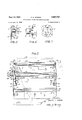
- FIG. l is a front view of the invention.
- FIG. 2 is a top plan view of the invention taken on the line 2-2 of FIG. l.
- FIG. 3 is a right end view on the line 3-3 of FIG. 2.
- FIG. 4 is a left end view on the line 4--4 of FIG. 2.
- FIG. 5 is a vertical, longitudinal section on the line 5-5 of FIG. 4.
- FIG. 6 is a vertical partial section on the line 6-6 of FIG. 2, showing a bearing for the rear ends of the dispensing and receiving rollers.
- FIG. 7 is a partial elevational view on the line 7--7 of FIG. 6.
- FIG. 8 is a vertical partial section on the line 8-8 of FIG. 2 showing the bearing at the front end of the dispensing roller.
- FIG. 9 is a vertical partial section on the line 9-9 of FIG. l showing said means for retarding rotation of the receiving roller.
- FIG. 10 is a partial view showing the slidable driving means in section at the limit of roller driving travel.
- FIG. 1l is a partial view showing said driving means at the limit of return travel.
- FIG. l2 is a top plan view of the driving means on the line 12-12 of FIG. 5.
- FIG. 13 is a side view of the driving means on the line 13-13 of FIG. 12.
- FIG. 14 is a sectional view of the driving means showing the brake, on line 14-14 of FIG. 13.
- the reference character 1 designates a toilet bowl (FIGS. 1, 2, 3 and 4), having a seat 2 hinged at its rear end to said bowl 3.
- a frame 4 en-Y p 2,987,732 Patented June 13, 1961 r' ICC closes said bowl and has a vertical front member 5, vertical rear members 6 and 7 separated by the bowl, and a top member 8 disposed in a horizontal plane between the bowl and the seat.
- Said top member is formed with an oval opening 9, and a marginal portion of said top member peripheral of said opening overlaps the top edge of the bowl.
- Braces Sa are adjustably xed to and beneath the top member to engage the bowl and prevent lateral movement of the frame.
- said top member 8 is formed with anges 10 and 11, downwardly bent and welded, brazed, or otherwise rigidly secured to said front and rear members.
- said top member is also formed with downwardly extending anges 12 'and 13, which add rigidity to the structure.
- braces 14 and 15 rigidly interconnect the upper and lower ends of the front member 5 and rear members 6 and 7.
- An additional brace 16 is removably applied in any conventional manner, to atord removal and replacement, as hereinafter explained, of a rolled strip of seat covers 31.
- a brace 17 is elongated between and interconnects the rear frame members 6 and 7.
- a seat cover dispensing roller 18 is journaled between said front frame member 5 and rear member 6.
- a seat cover receiving roller 19 is journaled between said front frame member and rear frame member 7.
- a rst driven roller 20 is journaled between frame members 5 and 6 in upwardly spaced relationship to the dispensing roller, and a second driven roller 21 is journaled between the front frame member and rear member 7 in upwardly spaced relationship to the receiving roller 19.
- Chain drive Said driven rollers may be journaled in any convenient manner, and are rotatively driven by sprocket wheels 22, 23, rigidly mounted on the front end portions of such rollers. Said sprocket wheels carry and are rotatively actuated by a chain 24.
- a chain driving mechanism 25 is Slidably mounted upon vertically spaced, parallel rods, 26, 27, extending between and supported by the right and left hand flanges 12 and 13. Said anges are notched at 12a and 13a to accommodate the upper span of said chain.
- Said driving mechanism is provided with a handle, 107 passing through a slot 28 in the front frame member 5. Said handle affords means for eecting sliding travel of the mechanism between the iirst and second driven rollers 20, 21.
- a spur 89 carried by the mechanism is, as hereinafter explained, engageable with a chain link to ⁇
- the sprocket wheel 23 rigidly and concentrically mounts a gear 29 which meshes with a larger gear 30, rotatably mounted upon the front frame member (FIGS. 1 and 4).
- Said larger gear meshes with a gear 75, a component of a slip clutchl 68 vmounted on the front end portion of the receiving roller 19.
- the roll of seat covers31 is carried by the dispensing rollerA 18, and the strip of said covers is drawn upwardly over the rst driven roller 20, across the seat 2, and thence downwardly Vover the second driven roller 21 to said receiving ⁇ roller 19.
- a roller 32 has'its end portions ournaled between the rear frame member 6 and a lug 33. Said lug is'bent transversely to the right hand flange 12, at the marginof they notch 12a. At its forward end, adiacentsaid lug, the roller 32 mounts a reel 34 on which is wound a tape 35, preferably of metal. Said tape has its end secured by screws 36 to said chain drive mechanism.
- a spring (not shown) is disposed in any conventional manner, so that as the chain Vdrive mechanism is slid in its chain driving travel, the tape is drawn from the reel, rotating said reel and the associated roller, thus applying tension to said spring, which tension urges said roller to rotate reversely, to Wind up said tape and thus 4 DC closing rollers are formed with reduced diameters S4 received in bearings 55.
- Said bearings are removable to aord removal of the rollers, and are formed with annular anges 56 formed withkeyhole slots 57. Said slots are removably engageable with header pins 58 to 'facilitate quick removal of said bearingsf.
- Friction wheel If the dispensing roller 18 were permitted to rotate freely each time a new seat vcover is drawn therefrom ⁇ as described above, there might occur anY ertcessive rotation of said roller, allowing'anV ⁇ accumulation of slack in the strip Yabout said roller. To prevent completel free rotation, therefore, the ⁇ front end of the roller-13 is socketed at 59 to receive land rotate upon ⁇ a stud 69 (FIG.- 8). Y Saidstud-is formed witha ange 61 by which it is secured to the front frame member Sby screws 62 or the like.
- Avfriction wheel 63 is also rotatably mount- .ed on said pin, and a pin 64 interconnects'said wheel land the roller 18 to provide mutual rotation thereof.
- Said pin 64 is rigidly received in the friction Wheel and removably received ⁇ in saidsocket- 59, to alford removal of the rollerY 18 without removal of the wheel 63.
- a friction strip 65 is passed over said wheel 63 with its ends extending downwardly. One such end is lixed upon a pin 66 projecting from the front frame member 5, While the other end is under tension of a spring 67. Such ,spring imposes sulicient friction upon the wheel to resist any Yundesired excessive rotation of said Wheel and the dispensing roller 18.
- the front frame member 5 has its upper end portion bent rearwardly and transversely to the plane of said 47a upon brackets 48 rigidly fixed to said flange 44and into position upon the seat 2.v
- the strip of used covers could be yallowed to accumulate within the housing vbeneath the second driven roller, disposal ofrsuch used 401 strip is more conveniently handled, by provision of the receiving ⁇ roller ⁇ 19, which must, of course', be driven rotatively, in order to wind-the used stripupon itself.
- Rods 49 rigidly interconnect the arms 47 of each pair of such arms to facilitate raising thereof in unison.
- each of said rollers 45 project through the respective arms 47 to be cradled in an arcuate notch 52 in an end of a rocker arm 50, when said arms 47 are swung downwardly (FIGS. 1, 2, and 5).
- Each of said rocker arms is interposed between an arm 47 and the respectively adjacent Yframe member, and secured to such frame member by a pivot 51.
- Springs 53 at the ends of said arms 50 remote from said notches 52, tend to counter the weight of the rollers 45. However,rsuch springs yield slightly when the paper strip is under tension, to reduce possibility of tearing said strip.
- Removable journals V The rearward end portions of both dispensing and rethe driven rollers 20, 21 a tearing of the strip.
- a slip clutch 68 (FIGS. 5 and 9) is mounted on the forward end portion and tensioning rollers B, or
- Such clutch includes an inner disc 70 con- Y frame member 5.
- a ratchet wheel 71 - is secured to the outer face of 'said disc by “rivets or screws (not shown), in concentric relation to the disc.
- a pin 72 is passed through the ratchet wheel and disc and into the roller to elfect rotation of said elements as a unit.
- a sleeve 73' is integrally formed upon the ratchet wheel, and projects through the front
- An outer disc 74 is concentrically and rotatably re- Y ceived upon ⁇ the sleeve as shown in FIG. 9.
- YThe aforementioned gear 75 is concentricallyvsecured by rivets or screws (not shown) to the outer face of saidn outer disc 74.
- a bearing 76 rotatably receives the outer end portion of the sleeve 73, and Iis formed with an annular auge, by which it is removablysecured tothe front frame member 5 by screws 77.
- 'I'he discs 70, 74 have an annular marginal portion extending beyond the diameter of the ratchet wheel 71, and between said discs at such marginal portion is disposed a plurality of driving pawls 78, pivoted at 79 upon the outer disc 74.
- Springs 80 are secured by pins 80a projecting from the inner face of the outer disc, and said springs urge the driving ends 81 of said pawls to engage the toothed periphery of Ithe ratchet wheel 71.
- the teeth of the ratchet wheel and the driving ends of the pawls are similarly modified to arcuate form, to allow said driving ends to slip over the teeth when the tension of the springs 80 is overcome by resistance of the strip of sea-t covers to withdrawal from the dispensing roller of more than one seat cover with each actuation of the driving mechanism 25.
- Such resistance is, of course imposed by the driving rollers and 21 in association with tensioning rollers 38, when due to the aforesaid increase in diameter of the roll of seat covers on the receiving roller 19, said roller tends to wind up a greater length of the strip than is fed to it by said driving rollers.
- the number of rotations made by the receiving roller is progressively reduced to wind only one seat cover thereon each time the chain driving mechanism is actuated.
- the chain driving mechanism (FIGS. 10 to 14) includes a housing formed with two parallel side walls 82 and 83 spaced apart by a web 84 disposed tra-.nsversely between such side walls, and secured thereto by screws 85, to form front land rear compartments 86, 87.
- the front compartment carries a vertically elongated shank 88, upwardly terminating in a spur 89.
- Said shank is upwardly slidable to extend the spur from the housing for engagement with a link of the chai-n 24 (FIGS. l1 and 13).
- Integral with the shank, and spaced from said spur 89 is a lug 90 formed with an arcuate cam face 91.
- Said lug effects a downward sliding of the shank to retract the spur within said housing, disengaging said spur from the chain
- a notch 92 in the side wall 83 accommodates a spring 93 which urges the shank into said upward travel and the web 84 is formed with a guide rib 94 to guide said shank in said sliding travel.
- a trip lever 95 is mounted in the front compartment 86 upon a pivot 96.
- Said lever is formed with a laterally projecting stop lug 97 which may be alternately received in or displaced from a notch 98 formed in the side of said shank 88.
- a spring 99 urges said trip lever about its pivotal axis to engage said stop in said notch, and said shank has its lower end portion 100 reduced in thickness to accommodate said spring 99.
- the front compartment is enclosed by a cover plate 102 removably secured to the housing by screws 103.
- the trip lever 95 is formed of thinner stock than the upper portion of the shank, said cover is provided with a vertically elongated, rectangular abutment 104 which closely confronts the trip lever to retain said lever upon its pivot.
- a pair of parallel flanges 105 extend outwardly from and transversely to the cover plate and pivotally secure between them at 105:1 an end portion 106 of the handle 107.
- a pair of levers 10S, A109 ank the housing and handle, and are pivoted between said anges at 110.
- Adjustable screws 111 are threaded into the outer ends of said levers to make actual contact with said handle.
- the trip lever 95 has a rearwardly otset upwardly extending trigger 112.
- a trigger actuating lever 113 has one end mounted by a pivot 114 in a coin slide enclosure 115. With the chain drive mechanism at the limit of its return sliding travel, a coin 116 may be inserted in coin slot 117.
- the coin is forced into a coin chute 121, and passing over an arcuate protuberance 113a on said lever 113, forces such lever downwardly about the pivot 114, to engage the trigger 112, moving the trip lever 95 about its pivotal axis to withdraw the stop 97 from the notch 98.
- the shank 88 then slides up responsive to the spring 93 extending the spur 89 into engagement with a chain link.
- a spring 123 returns the actuating lever 113 to its former position, and the coin drops down the chute 121 to a receptacle 122.
- the handle 107 is then grasped, and the chain driving mechanism 25 is urged in chain driving travel toward the second driven roller 21.
- the cam edge 91 of the lug 90 engages a lixed cam 124 mounted upon the left hand ilange 12, and is cammed downwardly, sliding the shank 88 down to retract the spur 89 within the housing.
- the spring 99 urges the trip lever about its pivot 96 to engage the stop 97 in the notch 98, thus retaining the spur in retracted position during sliding travel of the mechanism 25.
- the lower bushing 126 is longitudinally slotted at 127 to receive a brake shoe 128 dependent from a movable, lower cam 129, which cam slidably engages an upper cam 130.
- Said lower cam is socketed at 132 to receive a spring 133 which reacts against the head of a pin 134 to engage the lower cam against the upper cam, with a resultant downward movement of the lower cam, bringing the brake shoe into engagement With the upper surface ot the rod 27.
- the rearward end portion of lever 108 engages the pin 134, when the handle 107 is drawing the driving mechanism 25 in chain driving travel. Said lever forces the pin 134 inwardly and slides the lower cam 129 against the tension of the spring 133, and relieves said cam of the downward camming action of the upper cam to afford sliding travel of the driving mechanism on said rods 26, 27.
- the lever n 108 applies no force to the pin 134, and the spring 133 immediately acts to engage the two cams, and apply the brake shoe 128 to the rod 27 with suicient force to resist the return travel which would otherwise be induced by the aforesaid roller 32, reel 34, and tape 35.
- the lever 109 is pivoted by the handle 107, and presses the pin against the lower cam 129 compressing the spring 133 within said socket 132 and making a positive application of the brake shoe 128 to prevent such return travel.
- a lug 136 projecting laterally from the shank 8S is so positioned to project from the notch 92 as to prevent the lever 109 from applying the brake as described, and thus return travel of the mechanism 25 may be effected.
- the ends of the frame may be enclosed by any suitable covers (not shown), and that the trigger 112 may be actuated by means other than a. coin operated construction.
- a machine for dispensing paper seat covers for toilet seats including a frame adapted to enclose a toilet bowl and seat, a dispensing roller removably journaled within said frame at one side of such bowl to carry a rolled strip of such seat covers, a receiving roller removably journaled within said frame at the opposite side of such bowl, said strip being drawn from the dispensing l roller over such seat to said receiving roller, driven rollers, means to rotatively drive said driven rollers, to draw new seat coversinto position, a drive connection from one driven roller to said receiving roller to rotatively drive said receiving roller to wind used seat covers thereon, a slip clutch associated with said receiving roller to transmit driving force thereto, a pair of rollers straddling such seat and underlying such strip, means carried on the frame and actuable thereon for raising said rollers above said frame to lift said strip and afford cleaning of such seat.
- said last mentioned means being pairs of levers, each pair respectively journaling the end portions of a respective roller, pivot elements mounting said levers on the frame, whereby said levers may be swung about the axes of said pivot elements between an upper position to raise such strip above said frame for cleaning of such seat, and a lower position disposing said strip for use upon such seat.
- said resiliently yieldable means including a rocker arm disposed adjacent to each of said levers, said arms being paired with said pairs of levers, each arm having a roller-supporting end portion adapted to receive and support said rollers in their lower position, pivot elements mounting said arms on the frame, and spring means resisting rocking of said arms about said pivot elements, and resiliently yieldable to afford such rocking responsive to stress applied to said rollers by said strip of seat covers during transfer of said strip, to avert tearing of said strip under such stress.
- a machine for dispensing seat covers for toilet seats said machine including a ame adapted to enclose a toilet bowl and seat, a dispensing roller journaled in the frame to carry a rolled strip of seat covers, a receiving roller journaled in the frame, said rollers being disposed to straddle such bowl and said strip being drawn from the dispensing roller over such seat to connect with the receiving roller, means to rotatively drive said receiving roller to wind used seat covers thereon, said means including a pair of spaced rotatively driven rollers, and a drive connection from one of said driven rollers to said receiving roller, a rst and a second sprocket wheel respectively rigidly mounted on the respective driven rollers, an endless chain carried by and rotatively driving said sprocket wheels, a chain driving mechanism including a housing, a bar secured in said frame and elongated in substantially parallel relationship to the spans of the chain,
- said housing being mounted on said bar and slidable there- 5 on in chain-driving travel toward the second sprocket wheel and in return travel toward the first sprocket wheel, means carried by the housing to engage said chain during said chain-driving travel, and to release said chain during said return travel, and means onsaidframeat the limit of return travel to elect said engagement and means on said frame at the limit of said chain-driving travel to eiect such release.
- said means carried by the housing including a spur, an elongated shank mounting said spur, said shank being reciprocably slidaole in said housing to move the spur alternatively to engage or to release said chain, a spring urging the shank to engage the spur with the chain, restraining means in said housing actuable. to prei/ent or to afford response of the shank to said spring, said restraining means being actuable by said respective means on said frame.
- said spur being extended from said housing to engage said chain-link, and retracted within said housing when disengaged therefrom, said restraining means being releasably engageable with the shank when said spur is retracted, to maintain said spur in a retracted position.
- a machine as set forth in claim 8 said housing having a cam, said cam directing said brake shoe into said application responsive to said spring.V
- a machine as set forth in claim 9 a second lever actuable by said handle to positively apply said brake shoe to resist return travel of said chain drive mechanism during driving travel thereof.
- a machine as set forth in claim 10 a lug carried by said shank and projecting laterally from said housing to prevent actuation of said last mentioned lever when said spur is retracted during said return travel.
Landscapes
- Health & Medical Sciences (AREA)
- Public Health (AREA)
- Toilet Supplies (AREA)
Description
June 13, 1961 D. s. SPEESE TOILET-SEAT COVER DISPENSING MACHINE 6 Sheets-Sheet 1 Filed July 15, 1959 INVENTOR.
DANIEL S. SPEESE June 13, 1961 D. s. sPEEsE 2,987,732
TOILET-SEAT COVER DISPENSING MACHINE Filed July 15, 1959 6 Sheets-Sheet 2 JNVENToR.
Y DAN/EL 6T SPEESE 6 Sheets-Sheet 3 D. S. SPEESE TOILET-SEAT COVER DISPENSING MACHINE June 13, 1961 Filed July l5, 1959 DAN/EL S. SPEESE l l l l l/ June 13, 1961 p. s. sPEEsE TOILET-SEAT COVER DIsPENsING MACHINE 6 Sheets-Sheet 4 Filed July l5, 1959 NVENTOR.
DAN/EL S. SPEESE June 13, 1961 n. s. sPEEsE 2,987,732
TOILET-SEAT COVER DISPENSING MACHINE Filed July l5, 1959 6 Sheets-,Sheet 5 June 13, 1961 D. S. SPEESE TOILET-SEAT COVER DISPENSING MACHINE Filed July 15, 1959 Ir125 I3 17E-.ll lll' 6 Sheets-Sheet 6 /l mb sa 82 ge l 86 [w I I lh 7 /08 w 85 INVENToR.
DANIEL S. SPEESE BY United States Patent O 2,987,732 TOILET-SEAT COVER DISPENSING MACHINE Daniel S. Speese, 2711 Grand Ave. W., Detroit 38, Mich. Filed July 15, 1959, Ser. No. 827,292 11 Claims. (Cl. 4--247) This invention relates to devices for dispensing sanitary covers upon a toilet seat, and particularly devices which feed such covers successively in rolled strip form across a toilet seat, from a dispensing roller at one side thereof to a receiving roller at the other side.
An object of the invention is to provide driven rollers to draw said strip Ifrom the dispensing roller and feed it to the receiving roller.
Another object is to provide means manually slidable in roller driving travel in one direction, and manually slidable in non-driving return travel in the opposite direction.
Another object is to adapt said means to draw only one seat cover from the dispensing roller during each manipulation of said means in said driving travel.
Another object is to provide a brake to resist undesired return travel of said means until the Ilimit of driving travel is reached.
Another object is to adapt the invention to lrequire insertion in the construction of a coin as a prerequisite to electing said sliding travel.
Another object is to provide means to rotatively drive the receiving roller concurrently with said driven rollers, to wind used seat covers on the former as such covers are fed from the latter.
Still another object is to provide means to progressively retard rotation of the receiving roller as the diameter of used covers transferred thereto progressively increases.
There are various other objects attained by the construction hereinafter described and illustrated in the accompanying drawings, wherein:
FIG. l is a front view of the invention.
FIG. 2 is a top plan view of the invention taken on the line 2-2 of FIG. l.
FIG. 3 is a right end view on the line 3-3 of FIG. 2.
FIG. 4 is a left end view on the line 4--4 of FIG. 2.
FIG. 5 is a vertical, longitudinal section on the line 5-5 of FIG. 4.
FIG. 6 is a vertical partial section on the line 6-6 of FIG. 2, showing a bearing for the rear ends of the dispensing and receiving rollers.
FIG. 7 is a partial elevational view on the line 7--7 of FIG. 6.
FIG. 8 is a vertical partial section on the line 8-8 of FIG. 2 showing the bearing at the front end of the dispensing roller.
FIG. 9 is a vertical partial section on the line 9-9 of FIG. l showing said means for retarding rotation of the receiving roller.
FIG. 10 is a partial view showing the slidable driving means in section at the limit of roller driving travel.
FIG. 1l is a partial view showing said driving means at the limit of return travel.
FIG. l2 is a top plan view of the driving means on the line 12-12 of FIG. 5.
FIG. 13 is a side view of the driving means on the line 13-13 of FIG. 12.
FIG. 14 is a sectional view of the driving means showing the brake, on line 14-14 of FIG. 13.
' The frame In these views, the reference character 1 designates a toilet bowl (FIGS. 1, 2, 3 and 4), having a seat 2 hinged at its rear end to said bowl 3. A frame 4 en-Y p 2,987,732 Patented June 13, 1961 r' ICC closes said bowl and has a vertical front member 5, vertical rear members 6 and 7 separated by the bowl, and a top member 8 disposed in a horizontal plane between the bowl and the seat. Said top member is formed with an oval opening 9, and a marginal portion of said top member peripheral of said opening overlaps the top edge of the bowl. Braces Sa are adjustably xed to and beneath the top member to engage the bowl and prevent lateral movement of the frame.
At its front and rear, said top member 8 is formed with anges 10 and 11, downwardly bent and welded, brazed, or otherwise rigidly secured to said front and rear members. At each side of the bowl, said top member is also formed with downwardly extending anges 12 'and 13, which add rigidity to the structure.
On each side of the bowl, reinforcing braces 14 and 15 rigidly interconnect the upper and lower ends of the front member 5 and rear members 6 and 7. An additional brace 16 is removably applied in any conventional manner, to atord removal and replacement, as hereinafter explained, of a rolled strip of seat covers 31. At the rear of the bowl, a brace 17 is elongated between and interconnects the rear frame members 6 and 7.
Dispensing, receiving and driven rollers At the right side of the bowl (as seen in FIGS. l and 2), a seat cover dispensing roller 18 is journaled between said front frame member 5 and rear member 6. At the left side of said bowl a seat cover receiving roller 19 is journaled between said front frame member and rear frame member 7. A rst driven roller 20 is journaled between frame members 5 and 6 in upwardly spaced relationship to the dispensing roller, and a second driven roller 21 is journaled between the front frame member and rear member 7 in upwardly spaced relationship to the receiving roller 19. 1
tween the upper ends of a pair of arms 39. Said armsl are pivotally mounted at 39a upon brackets 40 fixed to the front and respective rear frame members. Springs 41 urge said arms about the axes of said pivots to bring said rollers 38 to bear against the strip of seat covers on the driven rollers 20, 21, with suicient pressure that said driven rollers, when rotatively actuated, will draw a new seat cover into position from the dispensing roller 18. Cams 42 are pivotal upon brackets 43, xed to the respective frame members, to act upon the lower ends of said arms in opposition to the springs 41 to swing said arms about their pivotal axes and move said rollers 38 away from said driven rollers and relieve the strip of seat covers from said pressure.
Chain drive Said driven rollers may be journaled in any convenient manner, and are rotatively driven by sprocket wheels 22, 23, rigidly mounted on the front end portions of such rollers. Said sprocket wheels carry and are rotatively actuated by a chain 24. A chain driving mechanism 25 is Slidably mounted upon vertically spaced, parallel rods, 26, 27, extending between and supported by the right and left hand flanges 12 and 13. Said anges are notched at 12a and 13a to accommodate the upper span of said chain. Said driving mechanism is provided with a handle, 107 passing through a slot 28 in the front frame member 5. Said handle affords means for eecting sliding travel of the mechanism between the iirst and second driven rollers 20, 21. A spur 89 carried by the mechanism is, as hereinafter explained, engageable with a chain link to `The sprocket wheel 23 rigidly and concentrically mounts a gear 29 which meshes with a larger gear 30, rotatably mounted upon the front frame member (FIGS. 1 and 4). Said larger gear meshes with a gear 75, a component of a slip clutchl 68 vmounted on the front end portion of the receiving roller 19. The roll of seat covers31 is carried by the dispensing rollerA 18, and the strip of said covers is drawn upwardly over the rst driven roller 20, across the seat 2, and thence downwardly Vover the second driven roller 21 to said receiving `roller 19. When the aforesaid chain driving travelrof the drive mechanism 25 is effected, the driven rollers 20, 21 withthe'co- 2' operation of the tensioning rollers 38, draws Va new seat cover into position, and the` receiving Vroller 19,.a ctuate'd through the gear train 29, Y 30, 475, winds upon itself a used seat cover.
Spring7 return roller Y To assist return-travel of the driving mechanism 25, a roller 32 has'its end portions ournaled between the rear frame member 6 and a lug 33. Said lug is'bent transversely to the right hand flange 12, at the marginof they notch 12a. At its forward end, adiacentsaid lug, the roller 32 mounts a reel 34 on which is wound a tape 35, preferably of metal. Said tape has its end secured by screws 36 to said chain drive mechanism. Within the roller, a spring (not shown) is disposed in any conventional manner, so that as the chain Vdrive mechanism is slid in its chain driving travel, the tape is drawn from the reel, rotating said reel and the associated roller, thus applying tension to said spring, which tension urges said roller to rotate reversely, to Wind up said tape and thus 4 ceiving rollers are formed with reduced diameters S4 received in bearings 55. Said bearings are removable to aord removal of the rollers, and are formed with annular anges 56 formed withkeyhole slots 57. Said slots are removably engageable with header pins 58 to 'facilitate quick removal of said bearingsf. i
Friction wheel If the dispensing roller 18 were permitted to rotate freely each time a new seat vcover is drawn therefrom `as described above, there might occur anY ertcessive rotation of said roller, allowing'anV `accumulation of slack in the strip Yabout said roller. To prevent completel free rotation, therefore, the `front end of the roller-13 is socketed at 59 to receive land rotate upon`a stud 69 (FIG.- 8). Y Saidstud-is formed witha ange 61 by which it is secured to the front frame member Sby screws 62 or the like. Avfriction wheel 63 is also rotatably mount- .ed on said pin, and a pin 64 interconnects'said wheel land the roller 18 to provide mutual rotation thereof. Said pin 64 is rigidly received in the friction Wheel and removably received`in saidsocket- 59, to alford removal of the rollerY 18 without removal of the wheel 63. A friction strip 65 is passed over said wheel 63 with its ends extending downwardly. One such end is lixed upon a pin 66 projecting from the front frame member 5, While the other end is under tension of a spring 67. Such ,spring imposes sulicient friction upon the wheel to resist any Yundesired excessive rotation of said Wheel and the dispensing roller 18.
' Slip clutch `will draw one seat cover from :the dispensing roller and draw the driving mechanism back toward the first driven l sprocket wheel.
Strip raising rollers The front frame member 5 has its upper end portion bent rearwardly and transversely to the plane of said 47a upon brackets 48 rigidly fixed to said flange 44and into position upon the seat 2.v Although the strip of used covers could be yallowed to accumulate within the housing vbeneath the second driven roller, disposal ofrsuch used 401 strip is more conveniently handled, by provision of the receiving `roller `19, which must, of course', be driven rotatively, in order to wind-the used stripupon itself. In this connection the problem arises that as the diameter of Vroll Yof used seat covers increases, the receiving roller will naturally tend to wind a greater length of the strip upon itself than `is being fed to it by the driven rollers.
" This could result in either a slippage of the strip between said rear frame members 6 and 7 respectively. Said rollers are situated beneath the strip of seat covers, so that when the strip of seat covers 31 is relieved of the pressure of the rollers 38, the arms 47 may be swung upwardly about their pivotal axes, raising said'rolle'rs 45,
to lift the strip of seat covers from the seat 2 to alford cleaning of said seat,(FIG. 1). Rods 49 rigidly interconnect the arms 47 of each pair of such arms to facilitate raising thereof in unison.
The end portions 46 of each of said rollers 45 project through the respective arms 47 to be cradled in an arcuate notch 52 in an end of a rocker arm 50, when said arms 47 are swung downwardly (FIGS. 1, 2, and 5). Each of said rocker arms is interposed between an arm 47 and the respectively adjacent Yframe member, and secured to such frame member by a pivot 51. Springs 53 at the ends of said arms 50 remote from said notches 52, tend to counter the weight of the rollers 45. However,rsuch springs yield slightly when the paper strip is under tension, to reduce possibility of tearing said strip.
Removable journals VThe rearward end portions of both dispensing and rethe driven rollers 20, 21 a tearing of the strip.
` To prevent such undesirable results, a slip clutch 68 (FIGS. 5 and 9) is mounted on the forward end portion and tensioning rollers B, or
69 of the receiving roller which end portion is of reduced diameter to accommodate the slip clutch. The
' components of such clutch include an inner disc 70 con- Y frame member 5.
c'zentrically mounted upon said end portion 69. A ratchet wheel 71 -is secured to the outer face of 'said disc by "rivets or screws (not shown), in concentric relation to the disc. A pin 72 is passed through the ratchet wheel and disc and into the roller to elfect rotation of said elements as a unit. A sleeve 73' is integrally formed upon the ratchet wheel, and projects through the front An outer disc 74 is concentrically and rotatably re- Y ceived upon` the sleeve as shown in FIG. 9. YThe aforementioned gear 75 is concentricallyvsecured by rivets or screws (not shown) to the outer face of saidn outer disc 74. A bearing 76 rotatably receives the outer end portion of the sleeve 73, and Iis formed with an annular auge, by which it is removablysecured tothe front frame member 5 by screws 77.
' I'he discs 70, 74 have an annular marginal portion extending beyond the diameter of the ratchet wheel 71, and between said discs at such marginal portion is disposed a plurality of driving pawls 78, pivoted at 79 upon the outer disc 74. Springs 80 are secured by pins 80a projecting from the inner face of the outer disc, and said springs urge the driving ends 81 of said pawls to engage the toothed periphery of Ithe ratchet wheel 71. The teeth of the ratchet wheel and the driving ends of the pawls are similarly modified to arcuate form, to allow said driving ends to slip over the teeth when the tension of the springs 80 is overcome by resistance of the strip of sea-t covers to withdrawal from the dispensing roller of more than one seat cover with each actuation of the driving mechanism 25. Such resistance is, of course imposed by the driving rollers and 21 in association with tensioning rollers 38, when due to the aforesaid increase in diameter of the roll of seat covers on the receiving roller 19, said roller tends to wind up a greater length of the strip than is fed to it by said driving rollers. Thus, the number of rotations made by the receiving roller is progressively reduced to wind only one seat cover thereon each time the chain driving mechanism is actuated.
Chain driving mechanism and brake The chain driving mechanism (FIGS. 10 to 14) includes a housing formed with two parallel side walls 82 and 83 spaced apart by a web 84 disposed tra-.nsversely between such side walls, and secured thereto by screws 85, to form front land rear compartments 86, 87. The front compartment carries a vertically elongated shank 88, upwardly terminating in a spur 89. Said shank is upwardly slidable to extend the spur from the housing for engagement with a link of the chai-n 24 (FIGS. l1 and 13). Integral with the shank, and spaced from said spur 89 is a lug 90 formed with an arcuate cam face 91. Said lug, as explained below, effects a downward sliding of the shank to retract the spur within said housing, disengaging said spur from the chain A notch 92 in the side wall 83 accommodates a spring 93 which urges the shank into said upward travel and the web 84 is formed with a guide rib 94 to guide said shank in said sliding travel.
A trip lever 95 is mounted in the front compartment 86 upon a pivot 96. Said lever is formed with a laterally projecting stop lug 97 which may be alternately received in or displaced from a notch 98 formed in the side of said shank 88. A spring 99 urges said trip lever about its pivotal axis to engage said stop in said notch, and said shank has its lower end portion 100 reduced in thickness to accommodate said spring 99. The front compartment is enclosed by a cover plate 102 removably secured to the housing by screws 103. As the trip lever 95 is formed of thinner stock than the upper portion of the shank, said cover is provided with a vertically elongated, rectangular abutment 104 which closely confronts the trip lever to retain said lever upon its pivot.
A pair of parallel flanges 105 extend outwardly from and transversely to the cover plate and pivotally secure between them at 105:1 an end portion 106 of the handle 107. A pair of levers 10S, A109 ank the housing and handle, and are pivoted between said anges at 110. When the handle is pulled in either direction of sliding travel of the mechanism 25, it pivots slightly about its pivotal axis, and engaging one of the levers, causes such lever to move about its own pivotal axis. Adjustable screws 111 are threaded into the outer ends of said levers to make actual contact with said handle. Thus the extent to which said levers are swung about their axes as aforesaid may be controlled by said adjusting screws.
The trip lever 95 has a rearwardly otset upwardly extending trigger 112. A trigger actuating lever 113 has one end mounted by a pivot 114 in a coin slide enclosure 115. With the chain drive mechanism at the limit of its return sliding travel, a coin 116 may be inserted in coin slot 117. Upon operation of a slide 118, by its handle `119, the coin is forced into a coin chute 121, and passing over an arcuate protuberance 113a on said lever 113, forces such lever downwardly about the pivot 114, to engage the trigger 112, moving the trip lever 95 about its pivotal axis to withdraw the stop 97 from the notch 98. The shank 88 then slides up responsive to the spring 93 extending the spur 89 into engagement with a chain link. A spring 123 returns the actuating lever 113 to its former position, and the coin drops down the chute 121 to a receptacle 122.
The handle 107 is then grasped, and the chain driving mechanism 25 is urged in chain driving travel toward the second driven roller 21. As said mechanism completes said travel the cam edge 91 of the lug 90 engages a lixed cam 124 mounted upon the left hand ilange 12, and is cammed downwardly, sliding the shank 88 down to retract the spur 89 within the housing. The spring 99 urges the trip lever about its pivot 96 to engage the stop 97 in the notch 98, thus retaining the spur in retracted position during sliding travel of the mechanism 25.
The brake Disposed between the side walls 82, 83 of the rear compartment, is a pair of tubular bushings 125, 126, having their ends mounted in the respective side walls. Said bushings occupy a vertically spaced relationship to slidably receive the aforesaid rods 26, 27, thus mounting the housing upon such rods. The lower bushing 126 is longitudinally slotted at 127 to receive a brake shoe 128 dependent from a movable, lower cam 129, which cam slidably engages an upper cam 130. Said lower cam is socketed at 132 to receive a spring 133 which reacts against the head of a pin 134 to engage the lower cam against the upper cam, with a resultant downward movement of the lower cam, bringing the brake shoe into engagement With the upper surface ot the rod 27. The headed pin 134 extends through the side wall 83, and a second headed pin =135 is aligned with the pin 134, and projects through the side wall 82. The rearward end portion of lever 108 engages the pin 134, when the handle 107 is drawing the driving mechanism 25 in chain driving travel. Said lever forces the pin 134 inwardly and slides the lower cam 129 against the tension of the spring 133, and relieves said cam of the downward camming action of the upper cam to afford sliding travel of the driving mechanism on said rods 26, 27.
if the handle 107 is accidentally released, the lever n 108 applies no force to the pin 134, and the spring 133 immediately acts to engage the two cams, and apply the brake shoe 128 to the rod 27 with suicient force to resist the return travel which would otherwise be induced by the aforesaid roller 32, reel 34, and tape 35. if an attempt is made to pull the mechanism in return travel before the driving travel is completed, the lever 109 is pivoted by the handle 107, and presses the pin against the lower cam 129 compressing the spring 133 within said socket 132 and making a positive application of the brake shoe 128 to prevent such return travel.
When the limit of driving travel is reached, however, and the spur y89 is retracted and retained as aforesaid in the housing, a lug 136 projecting laterally from the shank 8S, is so positioned to project from the notch 92 as to prevent the lever 109 from applying the brake as described, and thus return travel of the mechanism 25 may be effected.
It is understood that the ends of the frame may be enclosed by any suitable covers (not shown), and that the trigger 112 may be actuated by means other than a. coin operated construction.
What I claim is:
1. A machine for dispensing paper seat covers for toilet seats, said machine including a frame adapted to enclose a toilet bowl and seat, a dispensing roller removably journaled within said frame at one side of such bowl to carry a rolled strip of such seat covers, a receiving roller removably journaled within said frame at the opposite side of such bowl, said strip being drawn from the dispensing l roller over such seat to said receiving roller, driven rollers, means to rotatively drive said driven rollers, to draw new seat coversinto position, a drive connection from one driven roller to said receiving roller to rotatively drive said receiving roller to wind used seat covers thereon, a slip clutch associated with said receiving roller to transmit driving force thereto, a pair of rollers straddling such seat and underlying such strip, means carried on the frame and actuable thereon for raising said rollers above said frame to lift said strip and afford cleaning of such seat.
2. In a machine as set forth in claim 1, said last mentioned means being pairs of levers, each pair respectively journaling the end portions of a respective roller, pivot elements mounting said levers on the frame, whereby said levers may be swung about the axes of said pivot elements between an upper position to raise such strip above said frame for cleaning of such seat, and a lower position disposing said strip for use upon such seat.
3. In a machine as set forth in claim 2, resiliently yieldable means supporting said rollers in said lower position.
4. A machine as set forth in claim 2, said resiliently yieldable means including a rocker arm disposed adjacent to each of said levers, said arms being paired with said pairs of levers, each arm having a roller-supporting end portion adapted to receive and support said rollers in their lower position, pivot elements mounting said arms on the frame, and spring means resisting rocking of said arms about said pivot elements, and resiliently yieldable to afford such rocking responsive to stress applied to said rollers by said strip of seat covers during transfer of said strip, to avert tearing of said strip under such stress.
5. A machine for dispensing seat covers for toilet seats, said machine including a ame adapted to enclose a toilet bowl and seat, a dispensing roller journaled in the frame to carry a rolled strip of seat covers, a receiving roller journaled in the frame, said rollers being disposed to straddle such bowl and said strip being drawn from the dispensing roller over such seat to connect with the receiving roller, means to rotatively drive said receiving roller to wind used seat covers thereon, said means including a pair of spaced rotatively driven rollers, and a drive connection from one of said driven rollers to said receiving roller, a rst and a second sprocket wheel respectively rigidly mounted on the respective driven rollers, an endless chain carried by and rotatively driving said sprocket wheels, a chain driving mechanism including a housing, a bar secured in said frame and elongated in substantially parallel relationship to the spans of the chain,
said housing being mounted on said bar and slidable there- 5 on in chain-driving travel toward the second sprocket wheel and in return travel toward the first sprocket wheel, means carried by the housing to engage said chain during said chain-driving travel, and to release said chain during said return travel, and means onsaidframeat the limit of return travel to elect said engagement and means on said frame at the limit of said chain-driving travel to eiect such release.
6. A machine as set forth in claim 5, said means carried by the housing including a spur, an elongated shank mounting said spur, said shank being reciprocably slidaole in said housing to move the spur alternatively to engage or to release said chain, a spring urging the shank to engage the spur with the chain, restraining means in said housing actuable. to prei/ent or to afford response of the shank to said spring, said restraining means being actuable by said respective means on said frame.
7. A machine as set forth in claim 6, said spur being extended from said housing to engage said chain-link, and retracted within said housing when disengaged therefrom, said restraining means being releasably engageable with the shank when said spur is retracted, to maintain said spur in a retracted position.
8. A machine as set forth in claim 7, a brake shoe carried by said housing and applicable to a surface of said bar to resist sliding travel of the housing, a spring urging such application, a lever mounted upon said housing and actuable thereon to overcome said spring and resist such application when said spur is extended, and a handle mounted upon said housing to effect sliding travel thereof, and actuable upon said housing to actu ate said lever.
9. A machine as set forth in claim 8, said housing having a cam, said cam directing said brake shoe into said application responsive to said spring.V
10. A machine as set forth in claim 9, a second lever actuable by said handle to positively apply said brake shoe to resist return travel of said chain drive mechanism during driving travel thereof.
1l. A machine as set forth in claim 10, a lug carried by said shank and projecting laterally from said housing to prevent actuation of said last mentioned lever when said spur is retracted during said return travel.
References Cited in the file of this patent UNITED STATES PATENTS 827,162 Lesler July 3l, 1906 1,103,890 Mouat July 14, 1914 2,024,088 Benson Dec. l0, 1935 2,175,553 Altiery Oct. 10, 1939
Priority Applications (1)
| Application Number | Priority Date | Filing Date | Title |
|---|---|---|---|
| US827292A US2987732A (en) | 1959-07-15 | 1959-07-15 | Toilet-seat cover dispensing machine |
Applications Claiming Priority (1)
| Application Number | Priority Date | Filing Date | Title |
|---|---|---|---|
| US827292A US2987732A (en) | 1959-07-15 | 1959-07-15 | Toilet-seat cover dispensing machine |
Publications (1)
| Publication Number | Publication Date |
|---|---|
| US2987732A true US2987732A (en) | 1961-06-13 |
Family
ID=25248835
Family Applications (1)
| Application Number | Title | Priority Date | Filing Date |
|---|---|---|---|
| US827292A Expired - Lifetime US2987732A (en) | 1959-07-15 | 1959-07-15 | Toilet-seat cover dispensing machine |
Country Status (1)
| Country | Link |
|---|---|
| US (1) | US2987732A (en) |
Cited By (3)
| Publication number | Priority date | Publication date | Assignee | Title |
|---|---|---|---|---|
| US3961386A (en) * | 1974-03-27 | 1976-06-08 | Ferdinand Beno | Toilet seat cover |
| US4106135A (en) * | 1977-08-30 | 1978-08-15 | Lawrence Peska Associates, Inc. | Water closet basin assembly |
| US4769859A (en) * | 1986-12-09 | 1988-09-13 | Incorema | Sanitary closet with toilet seat protection cover |
Citations (4)
| Publication number | Priority date | Publication date | Assignee | Title |
|---|---|---|---|---|
| US827162A (en) * | 1905-06-21 | 1906-07-31 | Albert F Lesler | Sanitary device for closets. |
| US1103890A (en) * | 1913-02-27 | 1914-07-14 | Mary Mouat | Sanitary apparatus. |
| US2024088A (en) * | 1933-11-01 | 1935-12-10 | Newell B Benson | Sanitary toilet appliance |
| US2175553A (en) * | 1938-01-27 | 1939-10-10 | Altiery Nicholas | Sanitary toilet seat cover dispensing machine |
-
1959
- 1959-07-15 US US827292A patent/US2987732A/en not_active Expired - Lifetime
Patent Citations (4)
| Publication number | Priority date | Publication date | Assignee | Title |
|---|---|---|---|---|
| US827162A (en) * | 1905-06-21 | 1906-07-31 | Albert F Lesler | Sanitary device for closets. |
| US1103890A (en) * | 1913-02-27 | 1914-07-14 | Mary Mouat | Sanitary apparatus. |
| US2024088A (en) * | 1933-11-01 | 1935-12-10 | Newell B Benson | Sanitary toilet appliance |
| US2175553A (en) * | 1938-01-27 | 1939-10-10 | Altiery Nicholas | Sanitary toilet seat cover dispensing machine |
Cited By (3)
| Publication number | Priority date | Publication date | Assignee | Title |
|---|---|---|---|---|
| US3961386A (en) * | 1974-03-27 | 1976-06-08 | Ferdinand Beno | Toilet seat cover |
| US4106135A (en) * | 1977-08-30 | 1978-08-15 | Lawrence Peska Associates, Inc. | Water closet basin assembly |
| US4769859A (en) * | 1986-12-09 | 1988-09-13 | Incorema | Sanitary closet with toilet seat protection cover |
Similar Documents
| Publication | Publication Date | Title |
|---|---|---|
| US3858951A (en) | Towel dispenser | |
| US2987732A (en) | Toilet-seat cover dispensing machine | |
| DE1554607C3 (en) | Device for dispensing a continuous towel web | |
| US3893738A (en) | Retractable towel cabinet | |
| DE891268C (en) | Power-driven paper trolley elevator for typewriters u. like | |
| US2224572A (en) | Towel cabinet | |
| US5295272A (en) | Laid-on paper cut-off system for toilet seat | |
| US2975989A (en) | Mechanism for deleaving carbon strips | |
| US1913722A (en) | Paper towel dispenser | |
| US3273884A (en) | Automatic stop mechanism for arresting manual raising of feed tables | |
| US1962671A (en) | Duplicating machine | |
| US3506320A (en) | Apparatus for dispensing towelling | |
| US1964677A (en) | Autographic register | |
| NO117697B (en) | ||
| DE934668C (en) | Device for dispensing of towel crepe paper wound onto a supply roll or the like. | |
| US1846484A (en) | Dispensing device | |
| CH464974A (en) | Label dispenser with built-in printer | |
| US2002948A (en) | Device for placing protective coverings automatically on the seats of water closets | |
| US1703140A (en) | Duplicating machine | |
| US1765463A (en) | Sanitary toilet-seat cover | |
| US1611921A (en) | Autographic register | |
| DE207180C (en) | ||
| DE1511548C (en) | Device for advancing and cutting off an adhesive tape | |
| SU37600A1 (en) | Breeding machine for fonts, pictures, etc. from originals to sheets of paper, cardboard, etc., pre-coated with a layer of evaporating liquid | |
| US1901258A (en) | Autographic register |