US2987791A - Cuff link - Google Patents
Cuff link Download PDFInfo
- Publication number
- US2987791A US2987791A US773028A US77302858A US2987791A US 2987791 A US2987791 A US 2987791A US 773028 A US773028 A US 773028A US 77302858 A US77302858 A US 77302858A US 2987791 A US2987791 A US 2987791A
- Authority
- US
- United States
- Prior art keywords
- head
- shank
- pivoted
- spring
- recess
- Prior art date
- Legal status (The legal status is an assumption and is not a legal conclusion. Google has not performed a legal analysis and makes no representation as to the accuracy of the status listed.)
- Expired - Lifetime
Links
- 210000005069 ears Anatomy 0.000 description 3
- 230000000875 corresponding effect Effects 0.000 description 2
- APOYTRAZFJURPB-UHFFFAOYSA-N 2-methoxy-n-(2-methoxyethyl)-n-(trifluoro-$l^{4}-sulfanyl)ethanamine Chemical compound COCCN(S(F)(F)F)CCOC APOYTRAZFJURPB-UHFFFAOYSA-N 0.000 description 1
- 230000002596 correlated effect Effects 0.000 description 1
- 210000004905 finger nail Anatomy 0.000 description 1
- 230000000717 retained effect Effects 0.000 description 1
Images

Classifications
-
- A—HUMAN NECESSITIES
- A44—HABERDASHERY; JEWELLERY
- A44B—BUTTONS, PINS, BUCKLES, SLIDE FASTENERS, OR THE LIKE
- A44B5/00—Sleeve-links
- A44B5/002—Sleeve-links with head tiltable as a whole
-
- Y—GENERAL TAGGING OF NEW TECHNOLOGICAL DEVELOPMENTS; GENERAL TAGGING OF CROSS-SECTIONAL TECHNOLOGIES SPANNING OVER SEVERAL SECTIONS OF THE IPC; TECHNICAL SUBJECTS COVERED BY FORMER USPC CROSS-REFERENCE ART COLLECTIONS [XRACs] AND DIGESTS
- Y10—TECHNICAL SUBJECTS COVERED BY FORMER USPC
- Y10T—TECHNICAL SUBJECTS COVERED BY FORMER US CLASSIFICATION
- Y10T24/00—Buckles, buttons, clasps, etc.
- Y10T24/36—Button with fastener
- Y10T24/3617—Hinged leaf
Definitions
- the invention is more particularly concerned with a cuff link of the character embodying a cufi hole traversing shank having a fixed head on one end thereof and a head pivotally connected to the opposite end and adapted to be passed through aligned holes in the cuif.
- Cali links of the above noted general character as heretofore proposed or constructed have embodied yieldable means for retaining the pivotally connected head in general parallelism with the shank for entry through aligned cufi holes and the pivoted head being capable of restoration to an operative position upon relative light pressure on the pivoted head as to overcome the said yieldable means.
- a further object of the invention is the provision of a cult link which in consideration of the above structural features, embodies relatively few simple cooperating elements which are so correlated as not to become inoperative.
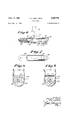
- FIG. 1 is a View in side elevation disclosing the several structural elements embodied in the improved cuff link in accordance with a first structural embodiment thereof.
- FIG. 2 is a bottom plan view of the pivoted head with the shank shown in transverse section.
- FIG. 3 is a top plan view of the pivoted head.
- FIG. 4 is a side elevational view of the cuff link with a portion of the pivoted head being broken away and in section and wherein a locking latch embodied in the structure and the shank and fixed head are shown in inoperative position in dotted lines.
- FIG. 5 is a view corresponding to FIG. 4 with the pivoted head in a position for entry through aligned cuif holes.
- FIG. 6 is a longitudinal sectional view of a modified form of pivoted head.
- FIG. 7 is a top plan view of the head shown in FIG. 6.
- FIG. 8 is an enlarged transverse sectional view as observed in the planes of broken line 88 on FIG. 6.
- FIG. 9 is a view corresponding to FIG. 8 but wherein adjustment has been made to hold the said pivoted head against pivoting action.
- the cufi link in accordance with the first embodiment thereof comprises a shank 10 whose one end is fixed centrally of the bottom of a head 11 which may be of any attractive form and the other end of the shank is disposed between a pair of ears 12 projecting inwardly from opposite sides of a head 13 and which ears are pivoted to the shank 10 by means of a pin 14.
- the head 13 is provided with a recess 15 and is also provided with an opening 16 for a purpose later to appear.
- the spring 18 is normally substantially flush with the said plane bottom wall, as is clearly indicated in vFIG. 5.
- the pivotal axis between the shank 10 and the head 13 is spaced equidistantly from the square free end of the shank, the opposite side edges of the shank and the inner face of thespring whereby upon parallelism of head 13 with the'head'11,
- the invention includes means for retaining the relative positions of the shank 10 and the head 13 as in FIGS. 4 and 5 and such means comprises a locking arm 19 which is of generally L-shape including an abutment portion 20 and a manipulating handle portion 21.
- the locking arm is normally disposed as indicated in solid lines in FIGS. 4 and 5 wherein same is pivoted to the head 13 by a pin 22 disposed within the opening 16 with the abutment portion 20 engaged with the spring 18 to resist movement thereof from its normal flat position to the inwardly bowed position indicated by dotted lines in FIG. 4 and in this normal position of the locking arm the handle portion 21 is seated in a recess 23 in the outer wall of the head 13 and said locking arm is preferably provided with a finger nail engageable extension 24 for facilitating withdrawal of the locking arm 19 from the recess 23.
- the axis of the pivot pin 22 is disposed off center of the abutment portion 29 whereby the locking arm may readily be swung to the dotted line positions in FIGS. 4 and 5.
- the cufi link is indicated in full lines in FIG. 4 with the cooperating elements thereof in their normal wearing positions and wherein the pivoted head 13 is incapable of swinging about the pivot pin 14.
- the locking arm 19 When, however, it is desired to install or remove the cuff link, the locking arm 19 is swung to the dotted positions of FIGS. 4 and 5 thereby freeing the spring 18 for flexing within the recess 15 as indicated in FIG. 4 with the result that pivotal action between the heads 11 and 13 is capable of being performed and the shank may then be placed in the position in FIG. 5 with one edge thereof engaged with the normally fiat spring 18 and in which position the head 13 may readily be threaded through aligned holes in a cuff.
- FIGS. 6 to 9 operates on the same general principle as that above described in connection with FIGS. 1 to 5, but is substantially different in structure.
- the head 30 is provided with a recess 31 and at one end of the recess is a shoulder 32 on which one end of a leaf spring 33 rests in substantially flush relation to the inner wall of the head.
- the opposite end of the spring 33 is frictionally engaged with a wall of the recess 31 and is normally dis- Patented June 13, 1 961 3 posed nearer the bottom of the recess than the first named end thereof.
- the shank 34 is pivoted between ears 35 projecting inwardly of the head and the squared end 34 of the shank in the position in FIG. 6 is capable of rotation about its pivotal connection whereby the head 30 may be swung into substantial parallel relation with the shank for threading the head through aligned holes in a cufl.
- a shaft 36 which is provided with a square cam 37 whose corners are disposed further from the axis of the shaft 36 than are the sides, upon one of which an end of the spring 33 rests as shown in FIGS. 6 and 8.
- a finger grip 38 is suitably secured to one end of the shaft 36for imparting rotation thereto.
- the shaft 36 and cam 37 have been rotated through an angle of 45 whereby a corner 39 thereof engages the spring 33 and elevates same to a position indicated by the dot-and-dash line in FIG. 6 and as also shown in FIG. 9 whereby the squared end of the'shaft 34 is firmly seated on the spring and thereby retained in right angular relation to the head 30.
- a culf link comprising a shank having a squared end, a
- said head pivotally connected to said end of the shank, said head being provided with a recess, an elongated spring plate spanning said recess and having one end thereof supported on said head and the other end thereof freely engaging a wall of the recess, a shaft rotatably supported in the head, and a cam rigid with the shaft and'being operable upon rotation of the shaft for moving said spring plate into engagement with said squared head to prevent relative rotation of the shank and the head, said cam being disposed adjacent the other end of the spring plate, and comprising a member of square configuration transversely of the shaft.
Landscapes
- Orthopedics, Nursing, And Contraception (AREA)
Description
June 13, 1961 P. A. BAST ETAL CUFF LINK 2 Sheets-Sheet 1 Filed Nov. 10, 1958 INVENTORS PaezZA. Bast BY [11' 6azie2:
WXM
United States Patent 2,987,791 CUFF LINK Paul A. Bast and Eli Sutker, both of 32 N. State St.,
Chicago, Ill. Filed Nov. 10, 1958, Ser. No. 773,028 1 Claim. (CI. 24-97) The invention is more particularly concerned with a cuff link of the character embodying a cufi hole traversing shank having a fixed head on one end thereof and a head pivotally connected to the opposite end and adapted to be passed through aligned holes in the cuif.
While various forms of cuff links of the above noted general character have heretofore been constructed and proposed, they have failed to fulfill the maximum requirements of cufif links of the general character above referred to.
Cali links of the above noted general character as heretofore proposed or constructed have embodied yieldable means for retaining the pivotally connected head in general parallelism with the shank for entry through aligned cufi holes and the pivoted head being capable of restoration to an operative position upon relative light pressure on the pivoted head as to overcome the said yieldable means.
While such forms of cuff links have been generally satisfactory, difiiculty has been experienced in holding the pivoted head against movement to its normal position when being entered through aligned cuff holes.
It is accordingly, a primary object of this invention to provide a cuif link which embodies structural features whereby the above noted objection is overcome.
A further object of the invention is the provision of a cult link which in consideration of the above structural features, embodies relatively few simple cooperating elements which are so correlated as not to become inoperative.
Other objects of the invention will become apparent in the course of the following detailed description taken in connection with the accompanying drawings, wherein:
FIG. 1 is a View in side elevation disclosing the several structural elements embodied in the improved cuff link in accordance with a first structural embodiment thereof.
FIG. 2 is a bottom plan view of the pivoted head with the shank shown in transverse section.
FIG. 3 is a top plan view of the pivoted head.
FIG. 4 is a side elevational view of the cuff link with a portion of the pivoted head being broken away and in section and wherein a locking latch embodied in the structure and the shank and fixed head are shown in inoperative position in dotted lines.
FIG. 5 is a view corresponding to FIG. 4 with the pivoted head in a position for entry through aligned cuif holes.
FIG. 6 is a longitudinal sectional view of a modified form of pivoted head.
FIG. 7 is a top plan view of the head shown in FIG. 6.
FIG. 8 is an enlarged transverse sectional view as observed in the planes of broken line 88 on FIG. 6.
FIG. 9 is a view corresponding to FIG. 8 but wherein adjustment has been made to hold the said pivoted head against pivoting action.
Referring now in detail to the drawings, and first to FIGS. 1 to 5 thereof, the cufi link in accordance with the first embodiment thereof comprises a shank 10 whose one end is fixed centrally of the bottom of a head 11 which may be of any attractive form and the other end of the shank is disposed between a pair of ears 12 projecting inwardly from opposite sides of a head 13 and which ears are pivoted to the shank 10 by means of a pin 14.
The head 13 is provided with a recess 15 and is also provided with an opening 16 for a purpose later to appear.
the spring 18 is normally substantially flush with the said plane bottom wall, as is clearly indicated in vFIG. 5.
As is indicated in FIGS. 4 and 5, the pivotal axis between the shank 10 and the head 13 is spaced equidistantly from the square free end of the shank, the opposite side edges of the shank and the inner face of thespring whereby upon parallelism of head 13 with the'head'11,
the end of the shank bears uniformly on the spring as is indicated in FIG. 4. Furthermore, upon movement of the shank about the pin 14 to the cuff hole inserting posi tion of FIG. 5, an edge of the shank 10 bears uniformly on the spring 18.
The invention includes means for retaining the relative positions of the shank 10 and the head 13 as in FIGS. 4 and 5 and such means comprises a locking arm 19 which is of generally L-shape including an abutment portion 20 and a manipulating handle portion 21.
The locking arm is normally disposed as indicated in solid lines in FIGS. 4 and 5 wherein same is pivoted to the head 13 by a pin 22 disposed within the opening 16 with the abutment portion 20 engaged with the spring 18 to resist movement thereof from its normal flat position to the inwardly bowed position indicated by dotted lines in FIG. 4 and in this normal position of the locking arm the handle portion 21 is seated in a recess 23 in the outer wall of the head 13 and said locking arm is preferably provided with a finger nail engageable extension 24 for facilitating withdrawal of the locking arm 19 from the recess 23.
At this point it is to be particularly observed that the axis of the pivot pin 22 is disposed off center of the abutment portion 29 whereby the locking arm may readily be swung to the dotted line positions in FIGS. 4 and 5.
The cufi link is indicated in full lines in FIG. 4 with the cooperating elements thereof in their normal wearing positions and wherein the pivoted head 13 is incapable of swinging about the pivot pin 14.
When, however, it is desired to install or remove the cuff link, the locking arm 19 is swung to the dotted positions of FIGS. 4 and 5 thereby freeing the spring 18 for flexing within the recess 15 as indicated in FIG. 4 with the result that pivotal action between the heads 11 and 13 is capable of being performed and the shank may then be placed in the position in FIG. 5 with one edge thereof engaged with the normally fiat spring 18 and in which position the head 13 may readily be threaded through aligned holes in a cuff.
With the shank 10 in the position of either FIG. 4 or FIG. 5, the locking arm 19 is swung to the solid line position.
The modified embodiment of the invention as disclosed in FIGS. 6 to 9 operates on the same general principle as that above described in connection with FIGS. 1 to 5, but is substantially different in structure.
Referring now in detail to the modified form of 011.5 link illustrated in FIGS. 6 to 9, the pivoted head only is disclosed and is designated as 30.
The head 30 is provided with a recess 31 and at one end of the recess is a shoulder 32 on which one end of a leaf spring 33 rests in substantially flush relation to the inner wall of the head.
The opposite end of the spring 33 is frictionally engaged with a wall of the recess 31 and is normally dis- Patented June 13, 1 961 3 posed nearer the bottom of the recess than the first named end thereof.
The shank 34, indicated by dotted lines in FIG. 6, is pivoted between ears 35 projecting inwardly of the head and the squared end 34 of the shank in the position in FIG. 6 is capable of rotation about its pivotal connection whereby the head 30 may be swung into substantial parallel relation with the shank for threading the head through aligned holes in a cufl.
' Rotatably supported within the head is a shaft 36 which is provided with a square cam 37 whose corners are disposed further from the axis of the shaft 36 than are the sides, upon one of which an end of the spring 33 rests as shown in FIGS. 6 and 8.
.A finger grip 38 is suitably secured to one end of the shaft 36for imparting rotation thereto.
As is indicated in FIG. 9, the shaft 36 and cam 37 have been rotated through an angle of 45 whereby a corner 39 thereof engages the spring 33 and elevates same to a position indicated by the dot-and-dash line in FIG. 6 and as also shown in FIG. 9 whereby the squared end of the'shaft 34 is firmly seated on the spring and thereby retained in right angular relation to the head 30.
Having set forth the invention in accordance with certain structural embodiments thereof, what is claimed and desired to be secured by US. Letters Patent is:
A culf link comprising a shank having a squared end, a
head pivotally connected to said end of the shank, said head being provided with a recess, an elongated spring plate spanning said recess and having one end thereof supported on said head and the other end thereof freely engaging a wall of the recess, a shaft rotatably supported in the head, and a cam rigid with the shaft and'being operable upon rotation of the shaft for moving said spring plate into engagement with said squared head to prevent relative rotation of the shank and the head, said cam being disposed adjacent the other end of the spring plate, and comprising a member of square configuration transversely of the shaft.
References Cited in the file of this patent UNITED STATES PATENTS
Priority Applications (1)
| Application Number | Priority Date | Filing Date | Title |
|---|---|---|---|
| US773028A US2987791A (en) | 1958-11-10 | 1958-11-10 | Cuff link |
Applications Claiming Priority (1)
| Application Number | Priority Date | Filing Date | Title |
|---|---|---|---|
| US773028A US2987791A (en) | 1958-11-10 | 1958-11-10 | Cuff link |
Publications (1)
| Publication Number | Publication Date |
|---|---|
| US2987791A true US2987791A (en) | 1961-06-13 |
Family
ID=25096970
Family Applications (1)
| Application Number | Title | Priority Date | Filing Date |
|---|---|---|---|
| US773028A Expired - Lifetime US2987791A (en) | 1958-11-10 | 1958-11-10 | Cuff link |
Country Status (1)
| Country | Link |
|---|---|
| US (1) | US2987791A (en) |
Citations (7)
| Publication number | Priority date | Publication date | Assignee | Title |
|---|---|---|---|---|
| US276978A (en) * | 1883-05-01 | Albert ottenbeimee | ||
| US356559A (en) * | 1887-01-25 | Isaac steinau | ||
| GB190613014A (en) * | 1906-06-05 | 1907-01-24 | Heinrich Rosenbund | Improvements in Collar and like Studs. |
| FR458389A (en) * | 1913-05-23 | 1913-10-09 | Jean Baptiste Vallet | Button enhancements for shirts |
| FR737620A (en) * | 1932-05-25 | 1932-12-14 | Cartier | Cufflink |
| FR942631A (en) * | 1947-03-04 | 1949-02-14 | Paul Mille | Advanced handlebar button |
| US2488102A (en) * | 1948-07-02 | 1949-11-15 | Benjamin J Strauss | Cuff link |
-
1958
- 1958-11-10 US US773028A patent/US2987791A/en not_active Expired - Lifetime
Patent Citations (7)
| Publication number | Priority date | Publication date | Assignee | Title |
|---|---|---|---|---|
| US276978A (en) * | 1883-05-01 | Albert ottenbeimee | ||
| US356559A (en) * | 1887-01-25 | Isaac steinau | ||
| GB190613014A (en) * | 1906-06-05 | 1907-01-24 | Heinrich Rosenbund | Improvements in Collar and like Studs. |
| FR458389A (en) * | 1913-05-23 | 1913-10-09 | Jean Baptiste Vallet | Button enhancements for shirts |
| FR737620A (en) * | 1932-05-25 | 1932-12-14 | Cartier | Cufflink |
| FR942631A (en) * | 1947-03-04 | 1949-02-14 | Paul Mille | Advanced handlebar button |
| US2488102A (en) * | 1948-07-02 | 1949-11-15 | Benjamin J Strauss | Cuff link |
Similar Documents
| Publication | Publication Date | Title |
|---|---|---|
| US4018412A (en) | Bracket for an operating table | |
| US2072463A (en) | Wrench | |
| US2090106A (en) | Jewelry finding | |
| US2987791A (en) | Cuff link | |
| US4045984A (en) | Key holder | |
| US2769322A (en) | Ear ring with ball joint for spacing clamping face from clamping arm | |
| GB1222952A (en) | Releasable fasteners | |
| US2658249A (en) | Cuff link | |
| US2732602A (en) | Quimby | |
| US2442920A (en) | Wrench for waterproof watchcases | |
| USRE21517E (en) | Nut lock for shears and the like | |
| US2599078A (en) | Automatically locking zipper | |
| US1593289A (en) | Ornament-securing means | |
| US3418699A (en) | Cuff link protector | |
| US2682190A (en) | Toggle bolt | |
| US3520035A (en) | Fastening device | |
| US1698843A (en) | Safety catch for badge pins | |
| US3725979A (en) | Button | |
| US1391620A (en) | Cuff-button | |
| US1814290A (en) | Brooch clasp | |
| US1323950A (en) | Bauer | |
| KR200486471Y1 (en) | Wrist protective supporter for bowling | |
| US3350749A (en) | Safety lock for cuff links | |
| JP2690150B2 (en) | Handle locking device for vending machines | |
| US2645834A (en) | Safety catch |