US2995010A - Adjustable propulsion nozzles - Google Patents
Adjustable propulsion nozzles Download PDFInfo
- Publication number
- US2995010A US2995010A US709316A US70931658A US2995010A US 2995010 A US2995010 A US 2995010A US 709316 A US709316 A US 709316A US 70931658 A US70931658 A US 70931658A US 2995010 A US2995010 A US 2995010A
- Authority
- US
- United States
- Prior art keywords
- series
- flaps
- nozzle
- link
- flap
- Prior art date
- Legal status (The legal status is an assumption and is not a legal conclusion. Google has not performed a legal analysis and makes no representation as to the accuracy of the status listed.)
- Expired - Lifetime
Links
- 230000007246 mechanism Effects 0.000 description 6
- 230000001276 controlling effect Effects 0.000 description 4
- 238000009740 moulding (composite fabrication) Methods 0.000 description 3
- 230000008901 benefit Effects 0.000 description 2
- 230000004048 modification Effects 0.000 description 2
- 238000012986 modification Methods 0.000 description 2
- 230000001105 regulatory effect Effects 0.000 description 2
- 230000004075 alteration Effects 0.000 description 1
- 230000008859 change Effects 0.000 description 1
- 238000002485 combustion reaction Methods 0.000 description 1
- 230000000694 effects Effects 0.000 description 1
Images

Classifications
-
- F—MECHANICAL ENGINEERING; LIGHTING; HEATING; WEAPONS; BLASTING
- F02—COMBUSTION ENGINES; HOT-GAS OR COMBUSTION-PRODUCT ENGINE PLANTS
- F02K—JET-PROPULSION PLANTS
- F02K1/00—Plants characterised by the form or arrangement of the jet pipe or nozzle; Jet pipes or nozzles peculiar thereto
- F02K1/06—Varying effective area of jet pipe or nozzle
- F02K1/12—Varying effective area of jet pipe or nozzle by means of pivoted flaps
- F02K1/1223—Varying effective area of jet pipe or nozzle by means of pivoted flaps of two series of flaps, the upstream series having its flaps hinged at their upstream ends on a fixed structure and the downstream series having its flaps hinged at their upstream ends on the downstream ends of the flaps of the upstream series
Definitions
- ADJUSTMSLE PROPULSION NOZZLES Filed Jan. 16, 1958 y 3 Sheets-Sheet l INvENToe W
- This invention relates to adjustable propulsion nozzles more especially for use in jet propulsion apparatus for aircraft, the term aircraft being used herein to include both piloted and unpiloted aircraft and missiles propelled partially or wholly by one or more propulsion jets.
- the ability to vary the throat area is of advantage in certain supersonic applications and also in combustion turbine engines having provision for reheat or after burning.
- An adjustable propulsion nozzle assembly comprises a fixed non-adjustable tubular nozzle to the rear edge of which are hinged, about axes tangential to a circle or circles having the axis of the fixed nozzle as centre, the forward ends of a series of iiaps extending rearwardly from their hinged ends, and with their adjacent edges arranged to overlap in the manner of petals and slide over one another in a circumferential sense, and including a second series of flaps lying downstream of the first series of iiaps and means for controlling independently the inclination of each series of flaps.
- the positions of the hinged forward ends of the second series of flaps determine the throat area of the nozzle when in convergent-divergent form.
- the control means for the flaps is preferably capable of locating the flaps in a large number of different positions between the limits of adjustment.
- the means controlling the inclination of the iiaps comprises a series of control elements, each connected between a moving part of a ap displaced from the hinge connection at its forward end, and a fixed structure surrounding the iiaps.
- a series of control elements may be connected respectively between a point on one of these aps displaced radially outwards from its hinged connection with one of the first series of fiaps, and a point on a fixed structure lying outside this second series of iiaps.
- each control element will then preferably be connected at one end to a point on or adjacent to the hinged connection between the forward end of the associated first ap and the fixed tubular nozzle, such that the inclination of each second liap with respect to the first is unaffected by alterations in the inclination of the first ap.
- control elements conveniently comprise pneumatic or hydraulic rams.
- control elements may be associated with a toggle mechanism, including two links pivotally attached to one another, thus increasing the mechanical advantage and also providing a self-locking effect in different operating positions.
- the inclination of the second series of iiaps is controlled by a parallel motion linkage including two parallel links one pivotally mounted on the hinged forward end of one of the rst series of flaps, and the other link pivotally attached to the first flap at a point spaced from this hinge, the second ap being attached to or formed integral with this second link.
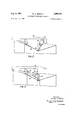
- FIGURE l is a sectional side elevation through the rear end of an adjustable exhaust nozzle
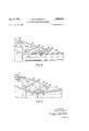
- FIGURES 2 and 3 are fragmentary sectional side elevations through alternative forms of adjusting mechanism according to the invention and FIGURES 4 and 5 are similar fragmentary sectional side elevations showing two positions of yet another form of adjusting mechanism.
- the fixed tubular nozzle lti is of cylindrical form and a first series of flaps 11 are hingedly attached at their forward ends to the nozzle on tangentially hinged axes 12 supported from a stationary structure 13 attached to and surrounding the rear end of the fixed nozzle.
- the hinge axis lies a short distance outside the forward end of the flap adjacent to the fixed nozzle and this part of the flap is radiused on the axis of the hinge so that a small clearance is maintained when the flap pivots.
- a flexible cover ring 14 is attached to the extreme rear end of the fixed nozzle 10, and engages the flaps 11 to form a substantially duid-tight seal.
- each second hinge axis 16 being substantially parallel to the corresponding first hinge axes at the forward ends of the respective pair of first flaps 11.
- Each of these second hinges 16 is also arranged to lie a short distance outside the general planes of the iiaps, which thus provide a substantially continuous inner surface which is rendered substantially gas tight by a resilient cover ring 17.
- the second series are arranged to overlap and slide over one another along their edges thus for-ming a complete duct of variable form.
- the angle of inclination of the flaps with respect to the common axis of the nozzle is preferably controlled by a series of control elements consisting of hydraulic rarns and toggle linkage.
- a series of control elements consisting of hydraulic rarns and toggle linkage.
- the inclination of each of the first seri-es of flaps is adjusted by a toggle linkage including a pair of links 2f?, 21 pivotally connected to one another and at their free ends respectively to one of the hinge oonnections 16 .between the iiaps of the first and second series, and at the other end pivotally connected at 22 to a rigid structure 23 surrounding the assembly.
- a series of rams 26 are provided around the nozzle assembly, one ram connected to each flap, and all the affected by movements of the first series of flaps.
- rams are connected hydraulically to one another and are thus moved in unison.
- the rams may be controlled by hydraulic valve mechanism including follow up linkages of known k-ind to provide accurate control of the positions of the flaps at any desired angular inclination within -their range of movement.
- each second fiap is preferably provided with an integral fiange 32 or other structure extending radially outwards from the common axis of the nozzle and the hydraulic ram is connected to they hinge pivot 3l on this ange appreciably spaced from the hinge axis 16 so as to afford an appreciable lever arm.
- each ram 30 since the forward end of each ram 30 is pivotally connected to the fixed nozzle structure adjacent to the :hinge axis 12 at the forward end of the first flap, the effective length of the ram 30 will not be affected by the movement of the first fiap.
- the inclination of the second fiaps in rela-tion to the first therefore depends purely on the 'adjustment of the second rams 30.
- Means may be provided for locking the rams and hence the various aps in several selected positions within the ra-nge of adjustment. Such means are well known in themselves and will therefore not be described in detail.
- the flaps may be infinitely adjustable. lt will be understood that the rams of each series of aps will be operated simultaneously, and in unison.
- the first series of iiaps 35 may be controlled by a series of simple hydraulic jacks 36 pivotally connected between points 37 on a surrounding fixed structure 38 and the hinged joints 39 at the downstream ends of the first flaps.
- each hydraulic ram 41 is connected to a bell crank lever 42 pivoted on the surrounding fixed structure 43 the other arm of the bell crank lever being pivotally connected to a link 44 vattached at its other end to one of the 4hinges 45 at the downstream ends of the first series of flaps 46.
- the object is to obtain independent control of the attitudes of the two series of flaps in such a way that the angular attitude of the second series of iiaps in relation to the axis of the complete assembly will be un-
- the first series of iiaps are each pivotally connected to the fixed nozzle structure 51 at a hinge pin 52, and each ap is rigidly connected to a lever 53, whose position can be adjusted by a longitudinally movable control member 54 such as a hydraulic or screw jack to control the angular position of the flap.
- a second longitudinally movable control member 55 is pivotally at- 'tached to a link S6, which is in turn pivoted at 58 to an extensible controlelement comprising a first link 57 and .a second link 59.
- the first link 57 which is free to -pivot at one end ou the hinge pin 52 is pivoted at its .other end to the link 56 at 58.
- the link 59 is pivoted at one end to -the junction 58, and at the other end to .a point'- 60 on one of the second series of iiaps 61.
- the link 57 is of the same length as link 63, the system j ⁇ thus forming a parallelogram linkage, the angular attitude of links 57 and 63 being controlled solely by the position 4 of control member 55, and unaffected by movements of the first flap 50.
- the second iiap 61 is connected to link 59 at the point 60, and is connected at another point 65 to a link 66 which is pivotally attached to an intermediate point 67 on the link 63, the dimensions of the parts being such that the pivots 65, 67, 62, 60, also comprise a parallelogram linkage.
- the second ap 61 is thus maintained at all times in the same angular attitude or position as the link 63, and hence as the link 57 which is in turn controlled by member 55.
- FIGURE 5 One possible alternative position of the various parts is illustrated in FIGURE 5. It will be appreciated that by providing a stop or other limit to the movement of control member 55 in the right hand direction in the drawings, it is possible to limit the inward deflection of the second series of flaps. In practise the stop may be so positioned that the second series of flaps cannot be come inclined Iinwards towards the axis of the nozzle, thus ensuring that the throat or smallest cross section of the nozzle assembly is always at the rear ends of the first series of flaps.
- a propulsion nozzle assembly comprising a fixed non-adjustable tubular nozzle, a first series of fiaps each hingedly connected at its forward end to the tubular nozzle on an axis tangential to a circle concentric with the axis of the fixed nozzle, and a second series of fiaps lying downstream of the first series of flaps, each second series flap being connected to one of said first series fiaps for pivotal movement about the forward end of said secone series flap, means for controlling the inclination of the first series of iiaps, said means comprising a first series of control elements each connected between a fixed structure rigid with the fixed nozzle and a point on one of the first series of aps displaced from the hinged connection at its forward end, and means for correlating the movement of said second series of flaps with and during movement of said first series which comprises a second series of control elements, each control element being connected between a pivot point substantially coaxial to the hinge axis of one of said first series of flaps
- a propulsion nozzle assembly as claimed in claim 1 in which one of said second series of flaps and one of said first series control members are pivotally connected to each of said first series flaps at a common point located near the downstream end of said first series fiap, and said second series of control members comprises a hydraulic cylinder and a piston slidable in said cylinder, said common point, said hinge axis, and the point at which said second series control member is attached to said second series fiap forming a triangle which is rigid for any given position of said piston in said cylinder, so that in the absence of any change in said piston position said second series flaps will swing with said first series flaps and maintain a substantially constant angle therebetween.
- each of said second series of control elements comprises first and second rigid links, one end of each link being pivotally connected to one end of the other link while the remaining ends of said links are connected to said coaxial pivot point and said fixed pivot point respectively, and said links constitute two elements of a parallel motion linkage by means of which each flap in said second series is connected to a flap in said rst series so that the angular position of said first series flap with respect to the axis of the nozzle may be altered without Ychanging the angular position of said second series fiap hingedly connected at its forward end to the tubular nozzle on an axis tangential to a circle concentric with the axis of the fixed nozzle, and a second series of aps lying downstream of the irst series of flaps, each second series iiap being connected to one of said first series of laps for pivotal movement about the forward end of said second series iiap, means for controlling the inclination of the first
- each of said series of extensible control elements comprises first and second rigid links, one end of each link being pivotally connected to one end of the other link, while the remaining end of the first link is connected to said coaxial pivot point and the remaining end of said second link is connected to said fixed pivot point.
- a propulsion nozzle assembly as claimed in claim 5 in which said means for regulating the extension of said rigidly extensible member comprises a control member for adjusting the inclination of each second series flap, said control member being connected between an anchorage point iixed with respect to said fixed nozzle and the pivotal connection between said links.
- a propulsion nozzle as claimed in claim 6 in which the position of said first link is unaffected by movement of said first series flap and said irst and second links form part of parallel motion linkage through which said second series fiap is connected to be parallel to said first link, so that the position of said second series flap is likewise unaffected by movement of said first series liap.
Landscapes
- Engineering & Computer Science (AREA)
- Chemical & Material Sciences (AREA)
- Combustion & Propulsion (AREA)
- Mechanical Engineering (AREA)
- General Engineering & Computer Science (AREA)
- Nozzles (AREA)
- Catching Or Destruction (AREA)
Applications Claiming Priority (1)
| Application Number | Priority Date | Filing Date | Title |
|---|---|---|---|
| GB346403X | 1957-01-17 |
Publications (1)
| Publication Number | Publication Date |
|---|---|
| US2995010A true US2995010A (en) | 1961-08-08 |
Family
ID=10368148
Family Applications (1)
| Application Number | Title | Priority Date | Filing Date |
|---|---|---|---|
| US709316A Expired - Lifetime US2995010A (en) | 1957-01-17 | 1958-01-16 | Adjustable propulsion nozzles |
Country Status (5)
| Country | Link |
|---|---|
| US (1) | US2995010A (de) |
| CH (1) | CH346403A (de) |
| DE (1) | DE1102494B (de) |
| FR (1) | FR1198435A (de) |
| GB (1) | GB858579A (de) |
Cited By (14)
| Publication number | Priority date | Publication date | Assignee | Title |
|---|---|---|---|---|
| US3163000A (en) * | 1960-11-28 | 1964-12-29 | Rolls Royce | Jet propulsion nozzle arrangements |
| US3174582A (en) * | 1962-09-26 | 1965-03-23 | Bertin & Cie | In flight jet silencer |
| US3214904A (en) * | 1960-11-28 | 1965-11-02 | Gen Electric | Variable area convergent-divergent nozzle and actuation system therefor |
| US3467312A (en) * | 1966-02-10 | 1969-09-16 | Gen Electric | Ejector nozzle |
| US3873027A (en) * | 1973-04-27 | 1975-03-25 | Snecma | Variable-geometry convergent-divergent nozzles |
| US4075833A (en) * | 1976-01-02 | 1978-02-28 | General Electric Company | Variable area inlet for a gas turbine engine |
| US4141501A (en) * | 1975-05-09 | 1979-02-27 | Rolls-Royce (1971) Limited | Nozzles for gas turbine engines |
| US4848664A (en) * | 1987-12-07 | 1989-07-18 | United Technologies Corporation | Yaw thrust vectoring exhaust nozzle |
| WO1990008254A1 (de) * | 1989-01-19 | 1990-07-26 | Mtu Motoren- Und Turbinen Union München Gmbh | Schubdüse |
| FR2653176A1 (fr) * | 1989-10-12 | 1991-04-19 | Gen Electric | Dispositif d'actionnement pour la mise en place d'une tuyere d'echappement pouvant etre vectorisee. |
| GB2404222A (en) * | 2003-07-21 | 2005-01-26 | United Technologies Corp | Turbine engine nozzle |
| CN114109648A (zh) * | 2021-11-12 | 2022-03-01 | 中国航发沈阳发动机研究所 | 一种可调喷管外罩机构 |
| US20240003316A1 (en) * | 2020-11-09 | 2024-01-04 | Safran Aircraft Engines | Turbojet engine rear part comprising a nozzle having flaps comprising levers that are movable by means of upstream and downstream bearing walls |
| US20240141852A1 (en) * | 2021-02-18 | 2024-05-02 | Safran Aircraft Engines | Turbojet engine rear portion having an augmented a9/a8 nozzle area ratio |
Families Citing this family (3)
| Publication number | Priority date | Publication date | Assignee | Title |
|---|---|---|---|---|
| DE2711217A1 (de) * | 1976-03-17 | 1977-09-22 | Rolls Royce 1971 Ltd | Verstellduese fuer gasturbinentriebwerke |
| FR2723764B1 (fr) * | 1994-08-18 | 1996-12-20 | Snecma | Etancheite entre volets suiveurs divergents et convergents d'une tuyere d'ejection de turboreacteur |
| US5813611A (en) * | 1996-09-27 | 1998-09-29 | United Technologies Corporation | Compact pressure balanced fulcrum-link nozzle |
Citations (4)
| Publication number | Priority date | Publication date | Assignee | Title |
|---|---|---|---|---|
| US2780056A (en) * | 1954-03-26 | 1957-02-05 | Rolls Royce | Jet-nozzle arrangement with outletarea varying means |
| US2801516A (en) * | 1953-04-10 | 1957-08-06 | Rolls Royce | Jet-nozzle arrangements with outlet area varying means |
| US2846843A (en) * | 1953-01-07 | 1958-08-12 | Curtiss Wright Corp | Variable area convergent-divergent exhaust nozzle and control therefor |
| US2858668A (en) * | 1952-09-27 | 1958-11-04 | Curtiss Wright Corp | Control for variable area convergentdivergent exhaust nozzle |
Family Cites Families (3)
| Publication number | Priority date | Publication date | Assignee | Title |
|---|---|---|---|---|
| US2724238A (en) * | 1950-10-25 | 1955-11-22 | Tresham D Gregg | Jet propulsive devices |
| US2625008A (en) * | 1951-02-28 | 1953-01-13 | Curtiss Wright Corp | Variable flow nozzle |
| GB774592A (en) * | 1954-05-18 | 1957-05-15 | Havilland Engine Co Ltd | Adjustable propulsion nozzles |
-
1957
- 1957-01-17 GB GB1851/57A patent/GB858579A/en not_active Expired
-
1958
- 1958-01-14 FR FR1198435D patent/FR1198435A/fr not_active Expired
- 1958-01-14 DE DEH32120A patent/DE1102494B/de active Pending
- 1958-01-16 US US709316A patent/US2995010A/en not_active Expired - Lifetime
- 1958-01-17 CH CH346403D patent/CH346403A/de unknown
Patent Citations (4)
| Publication number | Priority date | Publication date | Assignee | Title |
|---|---|---|---|---|
| US2858668A (en) * | 1952-09-27 | 1958-11-04 | Curtiss Wright Corp | Control for variable area convergentdivergent exhaust nozzle |
| US2846843A (en) * | 1953-01-07 | 1958-08-12 | Curtiss Wright Corp | Variable area convergent-divergent exhaust nozzle and control therefor |
| US2801516A (en) * | 1953-04-10 | 1957-08-06 | Rolls Royce | Jet-nozzle arrangements with outlet area varying means |
| US2780056A (en) * | 1954-03-26 | 1957-02-05 | Rolls Royce | Jet-nozzle arrangement with outletarea varying means |
Cited By (22)
| Publication number | Priority date | Publication date | Assignee | Title |
|---|---|---|---|---|
| US3163000A (en) * | 1960-11-28 | 1964-12-29 | Rolls Royce | Jet propulsion nozzle arrangements |
| US3214904A (en) * | 1960-11-28 | 1965-11-02 | Gen Electric | Variable area convergent-divergent nozzle and actuation system therefor |
| US3174582A (en) * | 1962-09-26 | 1965-03-23 | Bertin & Cie | In flight jet silencer |
| US3467312A (en) * | 1966-02-10 | 1969-09-16 | Gen Electric | Ejector nozzle |
| US3873027A (en) * | 1973-04-27 | 1975-03-25 | Snecma | Variable-geometry convergent-divergent nozzles |
| US4141501A (en) * | 1975-05-09 | 1979-02-27 | Rolls-Royce (1971) Limited | Nozzles for gas turbine engines |
| US4075833A (en) * | 1976-01-02 | 1978-02-28 | General Electric Company | Variable area inlet for a gas turbine engine |
| US4848664A (en) * | 1987-12-07 | 1989-07-18 | United Technologies Corporation | Yaw thrust vectoring exhaust nozzle |
| US5186390A (en) * | 1989-01-16 | 1993-02-16 | Mtu Motoren-Und Turbinen-Union Munchen Gmbh | Propelling nozzle |
| WO1990008254A1 (de) * | 1989-01-19 | 1990-07-26 | Mtu Motoren- Und Turbinen Union München Gmbh | Schubdüse |
| FR2653176A1 (fr) * | 1989-10-12 | 1991-04-19 | Gen Electric | Dispositif d'actionnement pour la mise en place d'une tuyere d'echappement pouvant etre vectorisee. |
| GB2404222A (en) * | 2003-07-21 | 2005-01-26 | United Technologies Corp | Turbine engine nozzle |
| US20070039328A1 (en) * | 2003-07-21 | 2007-02-22 | Petty Dale W | Turbine engine nozzle |
| US7225622B2 (en) | 2003-07-21 | 2007-06-05 | United Technologies Corporation | Turbine engine nozzle |
| GB2404222B (en) * | 2003-07-21 | 2008-01-09 | United Technologies Corp | Turbine engine nozzle |
| US20240003316A1 (en) * | 2020-11-09 | 2024-01-04 | Safran Aircraft Engines | Turbojet engine rear part comprising a nozzle having flaps comprising levers that are movable by means of upstream and downstream bearing walls |
| US12018628B2 (en) * | 2020-11-09 | 2024-06-25 | Safran Aircraft Engines | Turbojet engine rear part comprising a nozzle having flaps comprising levers that are movable by means of upstream and downstream bearing walls |
| US20240141852A1 (en) * | 2021-02-18 | 2024-05-02 | Safran Aircraft Engines | Turbojet engine rear portion having an augmented a9/a8 nozzle area ratio |
| EP4295025B1 (de) * | 2021-02-18 | 2025-01-29 | Safran Aircraft Engines | Hinterer teil eines turbostrahltriebwerks mit erweitertem a9/a8-düsenflächenverhältnis |
| US12429012B2 (en) * | 2021-02-18 | 2025-09-30 | Safran Aircraft Engines | Turbojet engine rear portion having an augmented A9/A8 nozzle area ratio |
| CN114109648B (zh) * | 2021-11-12 | 2023-02-28 | 中国航发沈阳发动机研究所 | 一种可调喷管外罩机构 |
| CN114109648A (zh) * | 2021-11-12 | 2022-03-01 | 中国航发沈阳发动机研究所 | 一种可调喷管外罩机构 |
Also Published As
| Publication number | Publication date |
|---|---|
| DE1102494B (de) | 1961-03-16 |
| GB858579A (en) | 1961-01-11 |
| FR1198435A (fr) | 1959-12-07 |
| CH346403A (de) | 1960-05-15 |
Similar Documents
| Publication | Publication Date | Title |
|---|---|---|
| US2995010A (en) | Adjustable propulsion nozzles | |
| US4176792A (en) | Variable area exhaust nozzle | |
| GB1293868A (en) | An arrangement for controlling and supporting a variable-geometry duct | |
| US3807637A (en) | Variable-geometry convergent-divergent nozzles for jet propulsion engines | |
| US2847823A (en) | Reverse thrust nozzle construction | |
| US5779152A (en) | Coordinated vectoring exhaust nozzle with scissors linkage | |
| US4280660A (en) | Vectorable nozzle | |
| US4196856A (en) | Variable geometry convergent divergent exhaust nozzle | |
| US4392615A (en) | Viol exhaust nozzle with veer flap extension | |
| US5437411A (en) | Vectoring exhaust nozzle flap and seal positioning apparatus | |
| JPH0257222B2 (de) | ||
| KR960013103B1 (ko) | 개스 터빈 엔진의 추력 조절용 2차원 배기 노즐 | |
| US4000610A (en) | Flight maneuverable nozzle for gas turbine engines | |
| US3979067A (en) | Actuating means for a thrust vectoring gas turbine engine exhaust nozzle | |
| US3352494A (en) | Supersonic jet propulsion nozzle | |
| JPH0396643A (ja) | 先細フラップ組立体、可変面積多機能排気ノズル及び2次元先細末広ノズル | |
| US3295764A (en) | Variable area exhaust nozzle | |
| GB1478075A (en) | Variable-area nozzles or other tubular members | |
| US2523842A (en) | Adjustable jet nozzle for jet propulsion units | |
| US5110050A (en) | Gas turbine engine nozzle | |
| US4993638A (en) | Thrust vectoring nozzle assembly | |
| US4817871A (en) | Control system for turbojet engine nozzle flaps | |
| US3214905A (en) | Variable area convergent-divergent nozzle | |
| US3612402A (en) | Thrust-controlling apparatus with variable axial flow area for differing flight regimes and thrust reversal | |
| US2699645A (en) | Variable-area control for jet nozzles having cooling air means |