US3034A - Improvement in plows - Google Patents
Improvement in plows Download PDFInfo
- Publication number
- US3034A US3034A US3034DA US3034A US 3034 A US3034 A US 3034A US 3034D A US3034D A US 3034DA US 3034 A US3034 A US 3034A
- Authority
- US
- United States
- Prior art keywords
- landside
- cutter
- mold
- board
- plows
- Prior art date
- Legal status (The legal status is an assumption and is not a legal conclusion. Google has not performed a legal analysis and makes no representation as to the accuracy of the status listed.)
- Expired - Lifetime
Links
- 238000005266 casting Methods 0.000 description 1
Images
Classifications
-
- A—HUMAN NECESSITIES
- A01—AGRICULTURE; FORESTRY; ANIMAL HUSBANDRY; HUNTING; TRAPPING; FISHING
- A01B—SOIL WORKING IN AGRICULTURE OR FORESTRY; PARTS, DETAILS, OR ACCESSORIES OF AGRICULTURAL MACHINES OR IMPLEMENTS, IN GENERAL
- A01B15/00—Elements, tools, or details of ploughs
- A01B15/02—Plough blades; Fixing the blades
- A01B15/04—Shares
Definitions
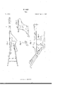
- Figure 1 is aview of the plow turned upside down; Fig. 2, a side view of the plow; Fig. 3, the landside of the cutter; Fig. 4, the moldboard, share, and point; Fig. 5, the mold-board side of the cutter.
- the beam A, clevis B, handles 0, share D, and point E are made in the usual manner.
- the improt'ement is in the mold-board F, cutter G and land-bar H, and fastenings I and K of the standard.
- the cutter G is made concave on the cuttingedge and convex on the side next the mold board,and correspoudin g with thefront thereof, and shaped on the sides to correspond with the curvature of the mold-board and the face of'the landside, extending from the land-bar nearly to the under side of the beam, having a tenon, G projecting from the rear or convex side of the cutter, which entersa corresponding mortise, P, in the front part ot'the mold-board, in which it is secured by a wedge or key, Q,or other suitable fastening, inserted horizontally through the landside and the aforesaid tenon.
- Several cutters of the aforesaid form and con'struction are cast with each plow in order to change them as they wear.
- the face of the cutter next the land is made to extend beyond the face of the landside, for
- Flanges K are formed on the upper end of the standard, which fits against the under side of the beam for the admission of two vertical screw-bolts, l, which pass through said flanges and the beam, having nuts on the upper ends of said bolts, screwed down firmly upon the upper side of the beam.
- a shoulder, R is cast on the inside of the land-bar, :gainstwhich the rear side of the share D is placed or abuts, and which removes the strain from the vertical bolt J, passing through the shale and mold-board, caused by the resistance in passing through the sward.
- the curvature of the mold-board F is such as to turn the sward with the least resistance, and it is made narrower across the middle, at F than at the top or bottom, for the purpose of reducing the friction of the mold-board in passing through thesward.
- the landside M is made shorter anddeeper than in 0th 1' plows, and the lower end of the handle nextv the landside is bolted to the tail end ofit in a position more elevated than is usual, so to be above the surface of the ground.
Landscapes
- Life Sciences & Earth Sciences (AREA)
- Engineering & Computer Science (AREA)
- Mechanical Engineering (AREA)
- Soil Sciences (AREA)
- Environmental Sciences (AREA)
- Soil Working Implements (AREA)
Description
, W. OGLE.
Plow.
Patented Apr. 6. 1843.
UNITED STATES PATENT OFFICE.
WM. OGLE, OF FREDERICK, MARYLAND.
IMPROVEMENT IN' PLOW'S.
Specification forming part of Letters Patent No. 3,034, dated April 6, 1843.
To all whom it may concern:
Be it known that I, WILLIAM OGLE, of the city of Frederick, in the county of Frederick and State of Maryland, have invented a new and useful Improvement in Plows, which is described as follows, reference being had to the annexed drawings of the same, making part of this specification.
Figure 1 is aview of the plow turned upside down; Fig. 2, a side view of the plow; Fig. 3, the landside of the cutter; Fig. 4, the moldboard, share, and point; Fig. 5, the mold-board side of the cutter.
Similar letters in the several figures lvfcl to corresponding parts.
The beam A, clevis B, handles 0, share D, and point E are made in the usual manner.
The improt'ement is in the mold-board F, cutter G and land-bar H, and fastenings I and K of the standard.
The cutter G is made concave on the cuttingedge and convex on the side next the mold board,and correspoudin g with thefront thereof, and shaped on the sides to correspond with the curvature of the mold-board and the face of'the landside, extending from the land-bar nearly to the under side of the beam, having a tenon, G projecting from the rear or convex side of the cutter, which entersa corresponding mortise, P, in the front part ot'the mold-board, in which it is secured by a wedge or key, Q,or other suitable fastening, inserted horizontally through the landside and the aforesaid tenon. Several cutters of the aforesaid form and con'struction are cast with each plow in order to change them as they wear. The face of the cutter next the land is made to extend beyond the face of the landside, for
4 the purpose of reducing the lrictiou which is two-eighths of an inch, more or less, as may be required, or until it is in the same vertical plane with the landside of the land-bar H. The projection referred to is indicated by the shading at G It is etfected in the casting of the cutter, which is made of sufficient size to produce therequired projection.
Flanges K are formed on the upper end of the standard, which fits against the under side of the beam for the admission of two vertical screw-bolts, l, which pass through said flanges and the beam, having nuts on the upper ends of said bolts, screwed down firmly upon the upper side of the beam.
A shoulder, R, is cast on the inside of the land-bar, :gainstwhich the rear side of the share D is placed or abuts, and which removes the strain from the vertical bolt J, passing through the shale and mold-board, caused by the resistance in passing through the sward.
The curvature of the mold-board F is such as to turn the sward with the least resistance, and it is made narrower across the middle, at F than at the top or bottom, for the purpose of reducing the friction of the mold-board in passing through thesward.
The landside M is made shorter anddeeper than in 0th 1' plows, and the lower end of the handle nextv the landside is bolted to the tail end ofit in a position more elevated than is usual, so to be above the surface of the ground.
What I vlaim as my invention, and whichI desire to secure by Letters Patent, is-
1. The manner of constructing and securing the cutter, as described.
2. Extending the landside face of the cutter beyond the face of the landside to reduce friction, as described. I 4
WILLIAM OGLE.
Witnesses:
EDM ND MAHER, A. E. J'oHNsoN.
Publications (1)
| Publication Number | Publication Date |
|---|---|
| US3034A true US3034A (en) | 1843-04-06 |
Family
ID=2063329
Family Applications (1)
| Application Number | Title | Priority Date | Filing Date |
|---|---|---|---|
| US3034D Expired - Lifetime US3034A (en) | Improvement in plows |
Country Status (1)
| Country | Link |
|---|---|
| US (1) | US3034A (en) |
Cited By (1)
| Publication number | Priority date | Publication date | Assignee | Title |
|---|---|---|---|---|
| US20080300491A1 (en) * | 2007-06-04 | 2008-12-04 | Medtronic, Inc. | Percutaneous needle guide and methods of use |
-
0
- US US3034D patent/US3034A/en not_active Expired - Lifetime
Cited By (1)
| Publication number | Priority date | Publication date | Assignee | Title |
|---|---|---|---|---|
| US20080300491A1 (en) * | 2007-06-04 | 2008-12-04 | Medtronic, Inc. | Percutaneous needle guide and methods of use |
Similar Documents
| Publication | Publication Date | Title |
|---|---|---|
| US4263A (en) | Improvement in plows | |
| US1360A (en) | Improvement in plows | |
| US3542A (en) | Improvement in plows | |
| US922A (en) | Improvement in plows | |
| US1320A (en) | Improvement in plows | |
| US327A (en) | Improvement in plows | |
| US1482A (en) | Improvement in the mode of constructing and fastening the shares and cutters of flows | |
| US112234A (en) | Improvement in plows | |
| US2132A (en) | Improvement in the construction of plows | |
| US3266A (en) | Improvement in plows | |
| US3372A (en) | Improvement in double plows | |
| US94367A (en) | Improvement in plows | |
| US23933A (en) | Improvement in plows | |
| US470913A (en) | flatau | |
| US3918A (en) | Improvement in plows | |
| US1175735A (en) | Listing-plow. | |
| US1178600A (en) | Plow. | |
| US77242A (en) | Jerome bacon | |
| US105531A (en) | Improvement in plows | |
| US151229A (en) | Improvement in plows | |
| US257807A (en) | Half to m | |
| US5148A (en) | Improvement in turf-plows | |
| USX9887I1 (en) | Improvement in plows | |
| US2515A (en) | Improvement in the construction of plows for prairie lands | |
| US345099A (en) | John w |