US3036266A - Electromechanical transducer - Google Patents
Electromechanical transducer Download PDFInfo
- Publication number
- US3036266A US3036266A US771553A US77155358A US3036266A US 3036266 A US3036266 A US 3036266A US 771553 A US771553 A US 771553A US 77155358 A US77155358 A US 77155358A US 3036266 A US3036266 A US 3036266A
- Authority
- US
- United States
- Prior art keywords
- head
- cylinder
- helical path
- magnetic
- pole
- Prior art date
- Legal status (The legal status is an assumption and is not a legal conclusion. Google has not performed a legal analysis and makes no representation as to the accuracy of the status listed.)
- Expired - Lifetime
Links
Images
Classifications
-
- G—PHYSICS
- G01—MEASURING; TESTING
- G01D—MEASURING NOT SPECIALLY ADAPTED FOR A SPECIFIC VARIABLE; ARRANGEMENTS FOR MEASURING TWO OR MORE VARIABLES NOT COVERED IN A SINGLE OTHER SUBCLASS; TARIFF METERING APPARATUS; MEASURING OR TESTING NOT OTHERWISE PROVIDED FOR
- G01D5/00—Mechanical means for transferring the output of a sensing member; Means for converting the output of a sensing member to another variable where the form or nature of the sensing member does not constrain the means for converting; Transducers not specially adapted for a specific variable
- G01D5/12—Mechanical means for transferring the output of a sensing member; Means for converting the output of a sensing member to another variable where the form or nature of the sensing member does not constrain the means for converting; Transducers not specially adapted for a specific variable using electric or magnetic means
- G01D5/14—Mechanical means for transferring the output of a sensing member; Means for converting the output of a sensing member to another variable where the form or nature of the sensing member does not constrain the means for converting; Transducers not specially adapted for a specific variable using electric or magnetic means influencing the magnitude of a current or voltage
- G01D5/20—Mechanical means for transferring the output of a sensing member; Means for converting the output of a sensing member to another variable where the form or nature of the sensing member does not constrain the means for converting; Transducers not specially adapted for a specific variable using electric or magnetic means influencing the magnitude of a current or voltage by varying inductance, e.g. by a movable armature
- G01D5/22—Mechanical means for transferring the output of a sensing member; Means for converting the output of a sensing member to another variable where the form or nature of the sensing member does not constrain the means for converting; Transducers not specially adapted for a specific variable using electric or magnetic means influencing the magnitude of a current or voltage by varying inductance, e.g. by a movable armature differentially influencing two coils
- G01D5/225—Mechanical means for transferring the output of a sensing member; Means for converting the output of a sensing member to another variable where the form or nature of the sensing member does not constrain the means for converting; Transducers not specially adapted for a specific variable using electric or magnetic means influencing the magnitude of a current or voltage by varying inductance, e.g. by a movable armature differentially influencing two coils by influencing the mutual induction between the two coils
- G01D5/2258—Mechanical means for transferring the output of a sensing member; Means for converting the output of a sensing member to another variable where the form or nature of the sensing member does not constrain the means for converting; Transducers not specially adapted for a specific variable using electric or magnetic means influencing the magnitude of a current or voltage by varying inductance, e.g. by a movable armature differentially influencing two coils by influencing the mutual induction between the two coils by a movable ferromagnetic element, e.g. core
-
- B—PERFORMING OPERATIONS; TRANSPORTING
- B23—MACHINE TOOLS; METAL-WORKING NOT OTHERWISE PROVIDED FOR
- B23Q—DETAILS, COMPONENTS, OR ACCESSORIES FOR MACHINE TOOLS, e.g. ARRANGEMENTS FOR COPYING OR CONTROLLING; MACHINE TOOLS IN GENERAL CHARACTERISED BY THE CONSTRUCTION OF PARTICULAR DETAILS OR COMPONENTS; COMBINATIONS OR ASSOCIATIONS OF METAL-WORKING MACHINES, NOT DIRECTED TO A PARTICULAR RESULT
- B23Q17/00—Arrangements for observing, indicating or measuring on machine tools
- B23Q17/22—Arrangements for observing, indicating or measuring on machine tools for indicating or measuring existing or desired position of tool or work
-
- B—PERFORMING OPERATIONS; TRANSPORTING
- B23—MACHINE TOOLS; METAL-WORKING NOT OTHERWISE PROVIDED FOR
- B23Q—DETAILS, COMPONENTS, OR ACCESSORIES FOR MACHINE TOOLS, e.g. ARRANGEMENTS FOR COPYING OR CONTROLLING; MACHINE TOOLS IN GENERAL CHARACTERISED BY THE CONSTRUCTION OF PARTICULAR DETAILS OR COMPONENTS; COMBINATIONS OR ASSOCIATIONS OF METAL-WORKING MACHINES, NOT DIRECTED TO A PARTICULAR RESULT
- B23Q35/00—Control systems or devices for copying directly from a pattern or a master model; Devices for use in copying manually
- B23Q35/04—Control systems or devices for copying directly from a pattern or a master model; Devices for use in copying manually using a feeler or the like travelling along the outline of the pattern, model or drawing; Feelers, patterns, or models therefor
- B23Q35/08—Means for transforming movement of the feeler or the like into feed movement of tool or work
- B23Q35/12—Means for transforming movement of the feeler or the like into feed movement of tool or work involving electrical means
-
- G—PHYSICS
- G01—MEASURING; TESTING
- G01D—MEASURING NOT SPECIALLY ADAPTED FOR A SPECIFIC VARIABLE; ARRANGEMENTS FOR MEASURING TWO OR MORE VARIABLES NOT COVERED IN A SINGLE OTHER SUBCLASS; TARIFF METERING APPARATUS; MEASURING OR TESTING NOT OTHERWISE PROVIDED FOR
- G01D5/00—Mechanical means for transferring the output of a sensing member; Means for converting the output of a sensing member to another variable where the form or nature of the sensing member does not constrain the means for converting; Transducers not specially adapted for a specific variable
- G01D5/12—Mechanical means for transferring the output of a sensing member; Means for converting the output of a sensing member to another variable where the form or nature of the sensing member does not constrain the means for converting; Transducers not specially adapted for a specific variable using electric or magnetic means
- G01D5/14—Mechanical means for transferring the output of a sensing member; Means for converting the output of a sensing member to another variable where the form or nature of the sensing member does not constrain the means for converting; Transducers not specially adapted for a specific variable using electric or magnetic means influencing the magnitude of a current or voltage
- G01D5/20—Mechanical means for transferring the output of a sensing member; Means for converting the output of a sensing member to another variable where the form or nature of the sensing member does not constrain the means for converting; Transducers not specially adapted for a specific variable using electric or magnetic means influencing the magnitude of a current or voltage by varying inductance, e.g. by a movable armature
- G01D5/2006—Mechanical means for transferring the output of a sensing member; Means for converting the output of a sensing member to another variable where the form or nature of the sensing member does not constrain the means for converting; Transducers not specially adapted for a specific variable using electric or magnetic means influencing the magnitude of a current or voltage by varying inductance, e.g. by a movable armature by influencing the self-induction of one or more coils
- G01D5/2013—Mechanical means for transferring the output of a sensing member; Means for converting the output of a sensing member to another variable where the form or nature of the sensing member does not constrain the means for converting; Transducers not specially adapted for a specific variable using electric or magnetic means influencing the magnitude of a current or voltage by varying inductance, e.g. by a movable armature by influencing the self-induction of one or more coils by a movable ferromagnetic element, e.g. a core
-
- G—PHYSICS
- G01—MEASURING; TESTING
- G01D—MEASURING NOT SPECIALLY ADAPTED FOR A SPECIFIC VARIABLE; ARRANGEMENTS FOR MEASURING TWO OR MORE VARIABLES NOT COVERED IN A SINGLE OTHER SUBCLASS; TARIFF METERING APPARATUS; MEASURING OR TESTING NOT OTHERWISE PROVIDED FOR
- G01D5/00—Mechanical means for transferring the output of a sensing member; Means for converting the output of a sensing member to another variable where the form or nature of the sensing member does not constrain the means for converting; Transducers not specially adapted for a specific variable
- G01D5/12—Mechanical means for transferring the output of a sensing member; Means for converting the output of a sensing member to another variable where the form or nature of the sensing member does not constrain the means for converting; Transducers not specially adapted for a specific variable using electric or magnetic means
- G01D5/14—Mechanical means for transferring the output of a sensing member; Means for converting the output of a sensing member to another variable where the form or nature of the sensing member does not constrain the means for converting; Transducers not specially adapted for a specific variable using electric or magnetic means influencing the magnitude of a current or voltage
- G01D5/20—Mechanical means for transferring the output of a sensing member; Means for converting the output of a sensing member to another variable where the form or nature of the sensing member does not constrain the means for converting; Transducers not specially adapted for a specific variable using electric or magnetic means influencing the magnitude of a current or voltage by varying inductance, e.g. by a movable armature
- G01D5/22—Mechanical means for transferring the output of a sensing member; Means for converting the output of a sensing member to another variable where the form or nature of the sensing member does not constrain the means for converting; Transducers not specially adapted for a specific variable using electric or magnetic means influencing the magnitude of a current or voltage by varying inductance, e.g. by a movable armature differentially influencing two coils
- G01D5/2208—Mechanical means for transferring the output of a sensing member; Means for converting the output of a sensing member to another variable where the form or nature of the sensing member does not constrain the means for converting; Transducers not specially adapted for a specific variable using electric or magnetic means influencing the magnitude of a current or voltage by varying inductance, e.g. by a movable armature differentially influencing two coils by influencing the self-induction of the coils
- G01D5/2216—Mechanical means for transferring the output of a sensing member; Means for converting the output of a sensing member to another variable where the form or nature of the sensing member does not constrain the means for converting; Transducers not specially adapted for a specific variable using electric or magnetic means influencing the magnitude of a current or voltage by varying inductance, e.g. by a movable armature differentially influencing two coils by influencing the self-induction of the coils by a movable ferromagnetic element, e.g. a core
Definitions
- This invention relates to precision measuring and locating or positioning devices, particularly for measuring the position of tables of machine tools or tool holders of machine tools although it may have application in other areas.
- the table may be positioned at any point relative to the machine bed while in fact the pick-up may only be positioned accurately directly opposite the magnetic members. While such a system may be satisfactory for some purposes, it introduces a discontinuity in that moving from one magnetic member to the next, the micrometer adjustment must be moved back to zero if it is desired to again position the table exactly opposite a zero point relative to the machine bed.
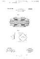
- FIGURE 1 is a sectional view of the present transducer device.
- FIG. 2 is a schematic diagram of the associated electrical circuit.
- FIGURE 1 there is shown a cylinder 2 which corre sponds to an ordinary steel lead screw having cut on its surface a square cut thread with the width of the thread equal to the width between the threads. In effect this leaves a spiral path down the lead screw where the steel has been cut away leaving only air which of course has a lower permeability than the steel.
- the cylinder may be any length as required and of course preferably extends over the full length of the desired operation of the machine tool or whatever device is being controlled. A section of the cylinder appears castellated due to existence of the lands 3.
- this cylinder is supported on the bed of the machine tool in such a position as to permit the proper corelation between the cylinder and the table or machine which is to be located, and also in such a manner as to permit rotational motion of the cylinder With a minimum error due to the displacement of the cylinder.
- both ends of the cylinder are preferably mounted in prestressed ball bearings to eliminate axial motion.
- a magnetic head 4 which has a body 5 which surrounds a portion of the cylinder. It does not actually engage the cylinder surface thus permitting the head to be moved axially of the cylinder.
- pole pieces 6 and 7. These pole pieces are es sentially annular in form and on their inner surfaces coaxial with the cylinder they are patterned in a manner similar to that threading existing on the surface of the cylinder, with a square cut thread leaving lands 8 and 9 which appear as a castellation in cross section.
- These lands preferably are of the same width as the lands on the cylinder 2 while the pitch of the thread is the same pitch as the pitch of the thread on the cylinder 2.
- annular recesses 10 and 11 At each end of the head 4 there are annular recesses 10 and 11 in which are mounted annular coils 12 and 13 which are fixed to the head 4 and surround the cylinder 2 but have such an internal diameter as not to interfere with the surface of the cylinder 2.
- the spacing of the poles 6 and 7 is such that when the lands of one pole are di' rectly opposite the lands of the cylinder 2, the lands of the other pole are directly opposite the grooves of the thread cut in the cylinder. In other words, the spacing is some practically desirable whole number of pitch lengths plus one-half of a pitch length.
- the whole head assembly is mounted to permit axial motion of the head 4 relative to the cylinder 2 but to prohibit rotational motion of the head relative to the controlled machine and the head is thusly coupled to the table or machine tool or whatever is to be positioned. Since the cylinder is fixed in its axial position, then by positioning the head relative to the cylinder, it is possible to position the machine tool or table relative to the cylinder 2 or in turn to position the head or tool relative to the machine as a whole, as may be desired.
- the signal across terminals 18 may be applied to any suitable indicator or to a servo mechanism and in either case the head may be adjusted until the inductance of both coils is equal which implies a specific physical relationship between the head 4 and the cylinder 2.
- This balancing may be produced in two mannersfirst by axial motion of the head, or second by a rotational motion of the cylinder. It will be appreciated that one complete rotation of the cylinder will be equivalent to a motion of the head one complete screw pitch. On the other hand, a portion of a complete revolution will be equivalent to a portion of a screw pitch of linear motion of the head.
- the position of the head 4 with respect to the cylinder 2 in terms of multiples of a thread pitch and fractions of a thread pitch while at all times it is only necessary to adjust the head 4 for a null output of the bridge.
- the transducer is a portion of a servo system, it will be apparent that the output from terminals 18 maybe applied either directly or through an amplifier to the terminals of a servo motor and thus to one phase of a two phase servo motor. The other phase of the servo motor is then connected to the A.C. supply and the rate of rotation of the servo motor will be proportional to the amplitude of the bridge output while the direction of rotation of the servo motor will be dependent upon the phase of output from the bridge circuit.
- the cylinder may then be supported intermediate its ends by means of trough type supports for example.
- trough type supports for example.
- the coil or coils need not surround the cylinder but only surround some portion of the magnetic path consisting of the pole, the head, the cylinder and any air gaps therebetween. The coil may therefore conveniently be moved intermediate the head and the pole if this portion is not annular.
- An electromechanical transducer comprising a first member of cylindrical form having around its cylindrical surface a first helical path of material having a different magnetic characteristic than the magnetic characteristic of the material from which said first member is formed, a second member at least partially surrounding the cylindrical surface of said first member and in close proximity thereto, with at least one portion of said second member having at least a portion of a second helical path and of material having a different magnetic characteristic than the magnetic characteristic of the material from which said second member is formed, said second helical path having substantially the same pitch as said first helical path, and magnetic reluctance sensing means positioned to sense the magnetic characteristic of the magnetic circuit including another portion of said second member not including said second helical path and said one portion of said second member having said second helical path, the gaps between said first and second members and at least a portion of said first member, and with at least one of said first and second members being formed from ferromagnetic material.
- An electromechanical transducer comprising a first member of cylindrical form having around its cylindrical surface a first helical path of material having a different magnetic characteristic than the magnetic characteristic of the material from which said first member is formed, a second member at least partially surrounding the cylindrical surface of said first member and in close proximity thereto, with at least one portion of said second member having at least a portion of a second helical path and of material having a different magnetic characteristic than the magnetic characteristic of the material from which said second member is formed, said second helical path having substantially the same pitch as said first helical path, and magnetic characteristic measurement means positioned to measure the magnetic characteristic of the magnetic circuit including another portion of said second member not including said second helical path and said one portion of said second member having said second helical path, the gaps between said first and second members and at least a portion of said first member, with at least one of said first and second members being formed from ferromagnetic material, and the material of at least one of said first and second helical paths being air.
- An electromechanical transducer comprising a first member of cylindrical form having around its cylindrical surface a first helical path of material having a different magnetic characteristic than the magnetic characteristic of the material from which said first member is formed, a second member comprising a head and a pair of poles all of which at least partially surround the cylindrical surface of said first member in close proximity thereto and being arranged in axial alignment with said head interposed between said poles, with one of said'poles having at least a portion of a second helical path of material having a different magnetic characteristic than the mag netic characteristic of the material from which the remainder of said one pole is formed and with said second path having the same pitch as said first helical path, and with the other of said poles having at least a portion of a third helical path similar to said second helical path, said second and third helical paths being spaced one from the other a whole number of pitch lengths plus one half of a pitch length, and magnetic characteristic comparison means operative with a first magnetic circuit including said one pole, a first portion
- An electromechanical transducer comprising a first member of cylindrical form having around its cylindrical surface a first helical path of material having a different magnetic characteristic than the magnetic characteristic of the material from which said first member is formed, a second member comprising a head and a pair of poles all of which at least partially surround the cylindrical surface of said first member in close proximity thereto and being arranged in axial alignment with said head interposed between said poles, with one of said poles having at least a portion of a second helical path of material having a different magnetic characteristic than the magnetic characteristic of the material from which the remainder of said one pole is formed and with said second path having the same pitch as said first helical path, and with the other of said poles having at least a portion of a third helical path similar to said second helical path, said second and third helical paths being spaced one from the other a whole number of pitch lengths plus one half of a pitch length, and magnetic comparison means operative to compare the magnetic characteristic of a first magnetic circuit including said one pole, a first portion
- An electromechanical transducer comprising a first member of cylindrical form having around its cylindrical surface a first helical path of material having a diiferent magnetic characteristic than the magnetic characteristic of the material from which said first member is formed, a second member comprising a head and a pair of poles all of which at least partially surround the cylindrical surface of said first member in close proximity thereto and being arranged in axial alignment with said head interposed between said poles, with one of said poles having at least a portion of a second helical path of material having a difierent magnetic characteristic than the magnetic characteristic of the material from which the remainder of said one pole is formed and with said second path having the same pitch as said first helical path, and with the other of said poles having at least a portion of a third helical path similar to said second helical path, said second and third helical paths being spaced one from the other a whole number of pitch lengths plus one half of a pitch length, and magnetic comparison means operative to compare the magnetic characteristic of a first magnetic circuit including said one
- An electromechanical transducer operative with a current supply and comprising a first member of cylindrical form having around its cylindrical surface a first helical path of material having a different magnetic characteristic than the magnetic characteristic of the material from which said first member is formed, a second member comprising a head and a pair of poles all of which at least partially surround the cylindrical surface of said first member in close proximity thereto and being arranged in axial alignment with said head interposed between said poles, with one of said poles having at least a portion of a second helical path of material having a different magnetic characteristic than the magnetic characteristic of the material from which the remainder of said one pole is formed and with said second path having the same pitch as said first helical path, and with the other of said poles having at least a portion of a third helical path similar to said second helical path, said second and third helical paths being spaced one from the other a whole number of pitch lengths plus one half of a pitch length, and magnetic field reluctance comparison means operative to compare the magnetic field
- An electromechanical transducer comprising a first member of cylindrical form having around its cylindrical surface a first helical path, a second member comprising a head and a pair of poles all of which at least partially surround the cylindrical surface of said first member in close proximity thereto and being arranged in axial alignment with said head interposed between said poles, with one of said poles having at least a portion of a second helical path and with said second path having the same pitch as said first helical path, and with the other of said poles having at least a portion of a third helical path similar to said second helical path, said second and third helical paths being spaced one from the other a whole number of pitch lengths plus one half of a pitch length, and magnetic characteristic comparison means operative with a first magnetic circuit including said one pole, a first portion of said head, a first portion of said first member and the gaps respectively between said one pole and said first member and between said head and said first member and operative with a second magnetic circuit including said other pole, at second portion of said
- An electromechanical transducer comprising a first member of cylindrical form having around its cylindrical surface a first helical path, a second member at least partially surrounding the cylindrical surface of said first member and in close proximity thereto, with at least one portion of said second member having at least a portion of a second helical path, said second helical path having substantially the same pitch as said first helical path, and magnetic reluctance sensing means positioned to sense the magnetic characteristic of the magnetic circuit including another portion of said second member not including said second helical path and said one portion of said second member having said second helical path, the gaps between said first and second members and at least a portion of said first member, and with at least one of said first and second members being formed from ferromagnetic material.
Landscapes
- Physics & Mathematics (AREA)
- General Physics & Mathematics (AREA)
- Engineering & Computer Science (AREA)
- Mechanical Engineering (AREA)
- Automation & Control Theory (AREA)
- Measurement Of Length, Angles, Or The Like Using Electric Or Magnetic Means (AREA)
Applications Claiming Priority (1)
| Application Number | Priority Date | Filing Date | Title |
|---|---|---|---|
| CA748371 | 1958-03-28 |
Publications (1)
| Publication Number | Publication Date |
|---|---|
| US3036266A true US3036266A (en) | 1962-05-22 |
Family
ID=4141041
Family Applications (1)
| Application Number | Title | Priority Date | Filing Date |
|---|---|---|---|
| US771553A Expired - Lifetime US3036266A (en) | 1958-03-28 | 1958-11-03 | Electromechanical transducer |
Country Status (5)
| Country | Link |
|---|---|
| US (1) | US3036266A (de) |
| CH (1) | CH382453A (de) |
| FR (1) | FR1271172A (de) |
| GB (1) | GB855637A (de) |
| NL (1) | NL108041C (de) |
Cited By (5)
| Publication number | Priority date | Publication date | Assignee | Title |
|---|---|---|---|---|
| US3281809A (en) * | 1966-10-25 | Differential transformer for register- ing linear movements utilizing bridge circuit windings and means for cali- bration | ||
| US3611345A (en) * | 1969-04-16 | 1971-10-05 | Intron Int Inc | Motion detector |
| US4112366A (en) * | 1975-09-25 | 1978-09-05 | Vyzkumny A Vyvojovy Ustav Zavodu Vseobecneho Strojirenstvi | Electromagnetic displacement scanner using an E-shaped core oblique to the scan direction |
| US4788499A (en) * | 1984-11-19 | 1988-11-29 | Kraftwerk Union Aktiengesellschaft | Method and eddy current test probe for the inspection of screws for nuclear reactor pressure vessels |
| US6253460B1 (en) * | 1999-06-10 | 2001-07-03 | Geoffrey W. Schmitz | Apparatus for position measurement and a system and a method for using the same |
Citations (3)
| Publication number | Priority date | Publication date | Assignee | Title |
|---|---|---|---|---|
| US2230945A (en) * | 1937-11-17 | 1941-02-04 | Gen Electric | Alternating current voltage regulator |
| US2430757A (en) * | 1944-11-14 | 1947-11-11 | Manning Maxwell & Moore Inc | Electrical remote-reading positionindicating apparatus |
| US2611964A (en) * | 1944-10-07 | 1952-09-30 | Buisson Pierr | Apparatus for measurments by variation of electrical capacity |
-
1958
- 1958-11-03 US US771553A patent/US3036266A/en not_active Expired - Lifetime
-
1959
- 1959-02-20 GB GB5913/59A patent/GB855637A/en not_active Expired
- 1959-03-19 NL NL237289A patent/NL108041C/xx active
- 1959-03-25 CH CH7125559A patent/CH382453A/de unknown
-
1960
- 1960-07-27 FR FR834101A patent/FR1271172A/fr not_active Expired
Patent Citations (3)
| Publication number | Priority date | Publication date | Assignee | Title |
|---|---|---|---|---|
| US2230945A (en) * | 1937-11-17 | 1941-02-04 | Gen Electric | Alternating current voltage regulator |
| US2611964A (en) * | 1944-10-07 | 1952-09-30 | Buisson Pierr | Apparatus for measurments by variation of electrical capacity |
| US2430757A (en) * | 1944-11-14 | 1947-11-11 | Manning Maxwell & Moore Inc | Electrical remote-reading positionindicating apparatus |
Cited By (5)
| Publication number | Priority date | Publication date | Assignee | Title |
|---|---|---|---|---|
| US3281809A (en) * | 1966-10-25 | Differential transformer for register- ing linear movements utilizing bridge circuit windings and means for cali- bration | ||
| US3611345A (en) * | 1969-04-16 | 1971-10-05 | Intron Int Inc | Motion detector |
| US4112366A (en) * | 1975-09-25 | 1978-09-05 | Vyzkumny A Vyvojovy Ustav Zavodu Vseobecneho Strojirenstvi | Electromagnetic displacement scanner using an E-shaped core oblique to the scan direction |
| US4788499A (en) * | 1984-11-19 | 1988-11-29 | Kraftwerk Union Aktiengesellschaft | Method and eddy current test probe for the inspection of screws for nuclear reactor pressure vessels |
| US6253460B1 (en) * | 1999-06-10 | 2001-07-03 | Geoffrey W. Schmitz | Apparatus for position measurement and a system and a method for using the same |
Also Published As
| Publication number | Publication date |
|---|---|
| NL108041C (nl) | 1963-11-15 |
| GB855637A (en) | 1960-12-07 |
| FR1271172A (fr) | 1961-09-08 |
| CH382453A (de) | 1964-09-30 |
Similar Documents
| Publication | Publication Date | Title |
|---|---|---|
| US2650352A (en) | Variable inductance for measuring motion | |
| US3011340A (en) | Means for measuring a torsional stress in a shaft of magnetostrictive material | |
| US3961243A (en) | Inductive displacement transducer using a bridge circuit having a stable voltage phase in the diagonal of the bridge | |
| US2440916A (en) | Precision measuring and positioning device | |
| US2445455A (en) | Electrical micrometer gauge | |
| US2831164A (en) | Transformer apparatus | |
| US2769969A (en) | Electromagnetic micrometer | |
| US4210865A (en) | Position sensor of linearly moving bodies | |
| US3153758A (en) | Current comparator device having plural magnetic cores and multiple windings | |
| US3694785A (en) | Temperature compensating differential transformer | |
| US3178696A (en) | Position transducers | |
| US3378763A (en) | Eddy current probe with temperature compensation | |
| US2213357A (en) | Direction indicating means | |
| US2457700A (en) | Torque meter | |
| US2880390A (en) | Apparatus for measuring small distances | |
| US2548397A (en) | Apparatus for measuring and transmitting a condition from a rotatable member | |
| US3113280A (en) | Electro-magnetic means for measuring a mechanical excursion | |
| US2922146A (en) | Measuring system with temperature compensation | |
| US2249477A (en) | Electric gauge | |
| US3151399A (en) | Differential transformer extensometer | |
| US3281809A (en) | Differential transformer for register- ing linear movements utilizing bridge circuit windings and means for cali- bration | |
| US2798200A (en) | Long-scale ratio instrument | |
| US2962652A (en) | Position indicator | |
| US2887656A (en) | Long scale electrical instrument | |
| GB855637A (en) | Electromechanical transducer |