US3053049A - Power plant installation - Google Patents
Power plant installation Download PDFInfo
- Publication number
- US3053049A US3053049A US731521A US73152158A US3053049A US 3053049 A US3053049 A US 3053049A US 731521 A US731521 A US 731521A US 73152158 A US73152158 A US 73152158A US 3053049 A US3053049 A US 3053049A
- Authority
- US
- United States
- Prior art keywords
- boiler
- gases
- steam
- gas turbine
- turbine
- Prior art date
- Legal status (The legal status is an assumption and is not a legal conclusion. Google has not performed a legal analysis and makes no representation as to the accuracy of the status listed.)
- Expired - Lifetime
Links
- 238000009434 installation Methods 0.000 title description 8
- 239000007789 gas Substances 0.000 description 111
- 230000007423 decrease Effects 0.000 description 14
- 239000000446 fuel Substances 0.000 description 14
- 230000000694 effects Effects 0.000 description 10
- 238000010438 heat treatment Methods 0.000 description 8
- QVGXLLKOCUKJST-UHFFFAOYSA-N atomic oxygen Chemical compound [O] QVGXLLKOCUKJST-UHFFFAOYSA-N 0.000 description 7
- 238000002485 combustion reaction Methods 0.000 description 7
- 239000001301 oxygen Substances 0.000 description 7
- 229910052760 oxygen Inorganic materials 0.000 description 7
- 230000008520 organization Effects 0.000 description 6
- XLYOFNOQVPJJNP-UHFFFAOYSA-N water Substances O XLYOFNOQVPJJNP-UHFFFAOYSA-N 0.000 description 5
- 239000000567 combustion gas Substances 0.000 description 3
- 238000011144 upstream manufacturing Methods 0.000 description 3
- 230000008859 change Effects 0.000 description 2
- 230000003247 decreasing effect Effects 0.000 description 2
- 238000010025 steaming Methods 0.000 description 2
- 206010037660 Pyrexia Diseases 0.000 description 1
- 230000008901 benefit Effects 0.000 description 1
- 239000004020 conductor Substances 0.000 description 1
- 238000010276 construction Methods 0.000 description 1
- 238000010304 firing Methods 0.000 description 1
- 239000002184 metal Substances 0.000 description 1
- 230000004048 modification Effects 0.000 description 1
- 238000012986 modification Methods 0.000 description 1
- 230000009467 reduction Effects 0.000 description 1
Images
Classifications
-
- F—MECHANICAL ENGINEERING; LIGHTING; HEATING; WEAPONS; BLASTING
- F01—MACHINES OR ENGINES IN GENERAL; ENGINE PLANTS IN GENERAL; STEAM ENGINES
- F01K—STEAM ENGINE PLANTS; STEAM ACCUMULATORS; ENGINE PLANTS NOT OTHERWISE PROVIDED FOR; ENGINES USING SPECIAL WORKING FLUIDS OR CYCLES
- F01K23/00—Plants characterised by more than one engine delivering power external to the plant, the engines being driven by different fluids
- F01K23/02—Plants characterised by more than one engine delivering power external to the plant, the engines being driven by different fluids the engine cycles being thermally coupled
- F01K23/06—Plants characterised by more than one engine delivering power external to the plant, the engines being driven by different fluids the engine cycles being thermally coupled combustion heat from one cycle heating the fluid in another cycle
- F01K23/10—Plants characterised by more than one engine delivering power external to the plant, the engines being driven by different fluids the engine cycles being thermally coupled combustion heat from one cycle heating the fluid in another cycle with exhaust fluid of one cycle heating the fluid in another cycle
- F01K23/103—Plants characterised by more than one engine delivering power external to the plant, the engines being driven by different fluids the engine cycles being thermally coupled combustion heat from one cycle heating the fluid in another cycle with exhaust fluid of one cycle heating the fluid in another cycle with afterburner in exhaust boiler
-
- F—MECHANICAL ENGINEERING; LIGHTING; HEATING; WEAPONS; BLASTING
- F02—COMBUSTION ENGINES; HOT-GAS OR COMBUSTION-PRODUCT ENGINE PLANTS
- F02C—GAS-TURBINE PLANTS; AIR INTAKES FOR JET-PROPULSION PLANTS; CONTROLLING FUEL SUPPLY IN AIR-BREATHING JET-PROPULSION PLANTS
- F02C6/00—Plural gas-turbine plants; Combinations of gas-turbine plants with other apparatus; Adaptations of gas-turbine plants for special use
- F02C6/18—Plural gas-turbine plants; Combinations of gas-turbine plants with other apparatus; Adaptations of gas-turbine plants for special use using the waste heat of gas-turbine plants outside the plants themselves, e.g. gas-turbine power heat plants
Definitions
- the invention involves this combination wherein the quantity of exhaust gases from the gas turbine is such that it provides an oxygen supply much greater than that required by the boiler to support com-
- a portion of the exhaust gases from the turbine are introduced into the boiler together with the fuel with which the boiler is fired with these exhaust gases supplying the oxygen necessary to support combustion of this fuel.
- the portion of the gases that are not introduced into the boiler are directed through a bypass duct within which is positioned economizer surface f the boiler and also within which is positioned a low temperature superheater section which is in series flow relation with a high temperature superheater section located within the boiler.
- Means are provided to controllably proportion the gas turbine gases introduced into the boiler and passed through the bypass.
- the organization is such as to provide a very eificient operation with the gas turbine gases having their temperature lowered to the point so that they can economically be discharged to atmosphere and at the same time a control of the superheat steam temperature is obtained.
- the boiler may be designed so that it can be operated without the turbine as when the turbine is shut down.
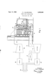
- the illustrative embodiment of the invention depicted therein comprises a gas turbine 16 that is of the type which produces substantially the same quantity of exhaust gas throughout the range of its operation, as for example, a single cycle, single shaft gas turbine.
- This turbine receives the hot gas supply from burners 12, which, in turn, receives compressed air from a compresser that is not here illustrated.
- the exhaust from turbine exits into duct 14, which, at the location 16, is divided into supply duct 18 that leads to boiler 20 and into bypass duct 22 which leads to stack 24 Via passage 36.
- Boiler 20 is tangentially fired in a conventional and well known manner by burners 26 and the exhaust turbine gases from supply duct 18 are admitted into the boiler through these burners. With these gases, which contain about 80% of the oxygen found in free air, supplying the oxygen requirements to support combustion of the fuel introduced into the boiler.
- This illustrative boiler has the walls of its furnace into which the fuel is tangentially introduced and burned lined with steam generating tubes and it is provided with a steam and water drum 28 and mud drum 30 between which there is disposed steam generating tubes in the conventional manner.
- Forming part of this boiler installation is the high temperature steam heating surface 32 which is in the form of a series of tube platens or groups in spaced relation across the boiler with there being suitable baffles provided so that the combustion gases flow in the boiler as is indicated by arrows 34.
- the combustion gases pass through the passage 35 into duct 36 within which is positioned economizer surface 38 of the boiler with these gases after traversing this economizer surface passing into stack 24.
- bypass duct 22 In order that the temperature of the turbine exhaust gases will be reduced to a suitably low value that these gases may economically be discharged to stack 24 there is provided in bypass duct 22 the economizer surface 4-2 which is supplementary to the economizer 38 and heats the water that is introduced into the steam and water drum 28 of the boiler with this surface 42 being a part of the surface for boiler 20. Also positioned in bypass duct 22 and upstream of economizer surface 42 is the low temperature superheater section 44. This superheater 44 receives steam from steam and water drum 28 through conduit 46, initially superheats this steam to some extent with the then superheated steam being conveyed to the high temperature superheater 32 by conduit 48.
- High temperature superheater 32 the steam is finally superheated to its desired temperature and is discharged through conduit 50 which leads to steam turbine 52.
- Low temperature superheater 44 is so related to the high temperature superheater 32 that the amount of heat imparted to the steam in high temperature superheater 32 is much greater than that imparted to the steam in passing through the low temperature superheater 44.
- the temperature head i.e., the temperature difierential between the steam and the gases passing over the superheater
- in low temperature superheater 44 is much less than in high tem perature superheater 32. The reason for having a large difference in the heat absorbing effectiveness of these two superheater sections will be apparent hereinafter.
- Gas turbine It ⁇ drives generator 52 while steam turbine 54 drives generator 56.
- Each of these generators is connected through suitable conductors to a common buss 58, which, in turn, connects to a varying load.
- Both of the aforementioned problems are solved by dividing the superheater into a low temperature section 44 and a high temperature section 32 as described hereinbefore. Only sufiicient superhea-t surface is provided in the high temperature section 32 to give the required steam temperature at the desired load when the boiler is operated independently of the gas turbine, i.e., only sufficient superheater surface is installed to obtain full steam temperature with coldair firing. Fan 33 supplies the air in this instance.
- the additional surface provided in low temperature section 44 is that amount of surface that is required for combined operation of the boiler and the gas turbine where only turbine gas is supplied to the boiler furnace to support combustion.
- boiler 20 may be operated When the gas turbine is shut down and the desired steam temperature obtained and when combined operation of the gas turbine and boiler is bad the additional heat required for superheating the steam is picked up in the low temperature superheater 44 and accordingly with this combined operation the required steam temperature is also obtained.
- a further advantage of this arrangement employing superheater section 44 in bypass 22 and upstream of economizer 42 is that there is a reduction in the amount of heat that must be imparted to economizer surface 42 in order to sufiiciently reduce the gas turbine gas temperature so that after traversing the surface 33 it may be discharged to stack 24- thereby reducing the possibility of and the amount of, if any, steaming in this economizer surface with it being desirable to maintain steaming in the economizer at a minimum so that scale and deposits will not form in the econo-mizer tubes.
- a control is provided for the proportioning of the gas turbine exhaust gases through the supply duct 18 and the bypass duct 22, i.e., the proportioning of the gases that goes to each of these locations is adjustably controlled.
- This control is in the form of adjustable damper 60 located at the inlet of supply duct 13 and adjustable damper 62 located at the inlet of bypass duct 22 with damper 62 being one of a plurality of dampers disclosed in side by side relation across the duct entrance. It will be appreciated that the represented dampers are only illustrative of a control to controllably proportion the turbine exhaust gas flow through each of these ducts.
- the gas turbine and boiler may both accommodate the varying load, i.e., the output of the gas turbine and the boiler may be varied to accommodate variations in load; the output of the gas turbine may be maintained constant and the boiler may accommodate the load variations, i.e., the output of the boiler may be the only element of the combination that is varied to accommodate load changes; and the output of the boiler may be maintained constant and the gas turbine varied to accommodate load changes, i.e., the output of the gas turbine may be the only element that is varied to accommodate changes in the load.
- this operation tends automatically to compensate for the tendency of the steam temperature to rise with a decrease in load when the weight flow of gas through the boiler remains constant. This is so because if the load changes and is accommodated jointly between boiler and the gas turbine the temperature of the gas turbine gases decreases although the quantity of these gases remains the same. If the dampers 62 and 69 are not moved from their former position so that the same quantity of gas turbine gases is supplied to the furnace the effect of high temperature superheater section 32 is to cause the steam temperature to rise with a decrease in load.
- the dampers 60 and 62 may be adjusted to provide what is in the nature of verier control in this instance, with damper 60 being moved to decrease the gas flow into the furnace and damper 62 moved to increase the proportion of the turbine gases that flows through bypass duct 22 as the load decreases. Since high temperature superheater section 32 has a much greater heating effect than low temperature superheater section 44 this adjustment of the dampers will effect a decrease in the steam temperature. Thus as the load on the power plant installation decreases a greater proportion of the gases are passed through bypass 22 and the steam temperature is maintained constant. When the load is increased the opposite control effect is had.
- dampers 62 and 6% may be adjusted so as to provide a generally constant steam temperature throughout the load range at which the boiler operates.
- the dampers are manipulated so that an increased portion of the gas turbine gases pass through the bypass 22 and accordingly over the low temperature superheated section 44. With an increase in load an opposite control effect is bad. With this control the temperature of the steam delivered to steam turbine 52 may be maintained generally constant.
- a gas turbine engine a boiler fired with a suitable fuel
- the turbine engine being such that the exhaust thereof provides a substantial excess of oxygen over that required to fire the boiler with the amount of exhaust gases remaining generally constant over a substantial load range
- Water heating heat exchange means forming part of the economizer surface of the boiler disposed in said bypass means to absorb heat from the bypassing turbine exhaust gases
- additional economizer surface over which both the bypass gases and the gases from the furnace pass a superheater for superheating the steam generated by the boiler and including a low temperature section disposed in said bypass means and a high temperature section located in the boiler said low temperature section and said high temperature section being such that the heat absorbed by the high temperature section is substantially greater than that absorbed by the low temperature section, and means provided to controllably proportion the turbine exhaust gases between the bypass means and the boiler.
- a vapor generator having a furnace fired with a suitable fuel
- means introducing a portion of the turbine exhaust gases into the furnace to support combustion of fuel therewithin means bypassing said furnace with the remainder of said gases
- said vapor generator having economizer surface a portion of which is in said bypass means to absorb heat from the bypassing turbine gases
- said vapor generator also having vapor heating surface one section of which is disposed in said bypass before the economizer to absorb heat from the bypassing turbine gases and another section of which is disposed to have the gases from the furnace pass thereover, and means operative to controllably proportion the turbine exhaust gases between the bypass means and the furnace.
Landscapes
- Engineering & Computer Science (AREA)
- Chemical & Material Sciences (AREA)
- Combustion & Propulsion (AREA)
- Mechanical Engineering (AREA)
- General Engineering & Computer Science (AREA)
- Engine Equipment That Uses Special Cycles (AREA)
Priority Applications (3)
| Application Number | Priority Date | Filing Date | Title |
|---|---|---|---|
| US731521A US3053049A (en) | 1958-04-28 | 1958-04-28 | Power plant installation |
| GB12171/59A GB857811A (en) | 1958-04-28 | 1959-04-10 | Power plant and method of operating the same |
| FR791905A FR1220532A (fr) | 1958-04-28 | 1959-04-13 | Perfectionnements apportés aux installations de force motrice comportant une turbine à gaz et une chaudière |
Applications Claiming Priority (1)
| Application Number | Priority Date | Filing Date | Title |
|---|---|---|---|
| US731521A US3053049A (en) | 1958-04-28 | 1958-04-28 | Power plant installation |
Publications (1)
| Publication Number | Publication Date |
|---|---|
| US3053049A true US3053049A (en) | 1962-09-11 |
Family
ID=24939872
Family Applications (1)
| Application Number | Title | Priority Date | Filing Date |
|---|---|---|---|
| US731521A Expired - Lifetime US3053049A (en) | 1958-04-28 | 1958-04-28 | Power plant installation |
Country Status (3)
| Country | Link |
|---|---|
| US (1) | US3053049A (fr) |
| FR (1) | FR1220532A (fr) |
| GB (1) | GB857811A (fr) |
Cited By (9)
| Publication number | Priority date | Publication date | Assignee | Title |
|---|---|---|---|---|
| US3420054A (en) * | 1966-09-09 | 1969-01-07 | Gen Electric | Combined steam-gas cycle with limited gas turbine |
| US3789804A (en) * | 1972-12-14 | 1974-02-05 | Sulzer Ag | Steam power plant with a flame-heated steam generator and a group of gas turbines |
| US4054107A (en) * | 1976-04-26 | 1977-10-18 | Combustion Engineering, Inc. | Marine waste heat steam generator |
| US4160805A (en) * | 1977-07-14 | 1979-07-10 | Hitachi Shipbuilding & Engineering Co. Ltd. | Boiler containing denitrator |
| US4706612A (en) * | 1987-02-24 | 1987-11-17 | Prutech Ii | Turbine exhaust fed low NOx staged combustor for TEOR power and steam generation with turbine exhaust bypass to the convection stage |
| US5517822A (en) * | 1993-06-15 | 1996-05-21 | Applied Energy Systems Of Oklahoma, Inc. | Mobile congeneration apparatus including inventive valve and boiler |
| US20110225972A1 (en) * | 2008-11-13 | 2011-09-22 | Siemens Aktiengesellschaft | Method for Operating a Waste Heat Steam Generator |
| CN102966495A (zh) * | 2012-11-09 | 2013-03-13 | 青海中控太阳能发电有限公司 | 一种塔式太阳能-蒸汽燃气联合循环发电系统 |
| CN107060917A (zh) * | 2016-12-16 | 2017-08-18 | 大唐东北电力试验研究所有限公司 | 利用机组旁路供热提高热电联产机组深度调峰系统及方法 |
Families Citing this family (1)
| Publication number | Priority date | Publication date | Assignee | Title |
|---|---|---|---|---|
| DE1178645B (de) * | 1962-03-08 | 1964-09-24 | Kohlenscheidungs Ges Mit Besch | Heizkraftwerk mit Gasturbine und Abhitzekessel |
Citations (6)
| Publication number | Priority date | Publication date | Assignee | Title |
|---|---|---|---|---|
| US1398946A (en) * | 1915-01-26 | 1921-11-29 | Superheater Co Ltd | Power engine plant |
| US1925646A (en) * | 1933-06-29 | 1933-09-05 | Foster Wheeler Corp | Waste heat boiler heated by gases from diesel engines or the like |
| US2107440A (en) * | 1934-09-08 | 1938-02-08 | Superheater Co Ltd | Compensating reheater and superheater |
| US2223953A (en) * | 1937-09-27 | 1940-12-03 | Harry W Davis | Turbine |
| US2471755A (en) * | 1944-01-05 | 1949-05-31 | Oerlikon Maschf | Steam-air-thermal power plant |
| US2604755A (en) * | 1948-12-23 | 1952-07-29 | Laval Steam Turbine Co | Combined gas and steam turbine plant using burner in gas turbine exhaust to heat steam |
-
1958
- 1958-04-28 US US731521A patent/US3053049A/en not_active Expired - Lifetime
-
1959
- 1959-04-10 GB GB12171/59A patent/GB857811A/en not_active Expired
- 1959-04-13 FR FR791905A patent/FR1220532A/fr not_active Expired
Patent Citations (6)
| Publication number | Priority date | Publication date | Assignee | Title |
|---|---|---|---|---|
| US1398946A (en) * | 1915-01-26 | 1921-11-29 | Superheater Co Ltd | Power engine plant |
| US1925646A (en) * | 1933-06-29 | 1933-09-05 | Foster Wheeler Corp | Waste heat boiler heated by gases from diesel engines or the like |
| US2107440A (en) * | 1934-09-08 | 1938-02-08 | Superheater Co Ltd | Compensating reheater and superheater |
| US2223953A (en) * | 1937-09-27 | 1940-12-03 | Harry W Davis | Turbine |
| US2471755A (en) * | 1944-01-05 | 1949-05-31 | Oerlikon Maschf | Steam-air-thermal power plant |
| US2604755A (en) * | 1948-12-23 | 1952-07-29 | Laval Steam Turbine Co | Combined gas and steam turbine plant using burner in gas turbine exhaust to heat steam |
Cited By (11)
| Publication number | Priority date | Publication date | Assignee | Title |
|---|---|---|---|---|
| US3420054A (en) * | 1966-09-09 | 1969-01-07 | Gen Electric | Combined steam-gas cycle with limited gas turbine |
| US3789804A (en) * | 1972-12-14 | 1974-02-05 | Sulzer Ag | Steam power plant with a flame-heated steam generator and a group of gas turbines |
| US4054107A (en) * | 1976-04-26 | 1977-10-18 | Combustion Engineering, Inc. | Marine waste heat steam generator |
| US4160805A (en) * | 1977-07-14 | 1979-07-10 | Hitachi Shipbuilding & Engineering Co. Ltd. | Boiler containing denitrator |
| US4706612A (en) * | 1987-02-24 | 1987-11-17 | Prutech Ii | Turbine exhaust fed low NOx staged combustor for TEOR power and steam generation with turbine exhaust bypass to the convection stage |
| US5517822A (en) * | 1993-06-15 | 1996-05-21 | Applied Energy Systems Of Oklahoma, Inc. | Mobile congeneration apparatus including inventive valve and boiler |
| US20110225972A1 (en) * | 2008-11-13 | 2011-09-22 | Siemens Aktiengesellschaft | Method for Operating a Waste Heat Steam Generator |
| US9593844B2 (en) * | 2008-11-13 | 2017-03-14 | Siemens Aktiengesellschaft | Method for operating a waste heat steam generator |
| CN102966495A (zh) * | 2012-11-09 | 2013-03-13 | 青海中控太阳能发电有限公司 | 一种塔式太阳能-蒸汽燃气联合循环发电系统 |
| CN102966495B (zh) * | 2012-11-09 | 2015-02-11 | 青海中控太阳能发电有限公司 | 一种塔式太阳能-蒸汽燃气联合循环发电系统 |
| CN107060917A (zh) * | 2016-12-16 | 2017-08-18 | 大唐东北电力试验研究所有限公司 | 利用机组旁路供热提高热电联产机组深度调峰系统及方法 |
Also Published As
| Publication number | Publication date |
|---|---|
| FR1220532A (fr) | 1960-05-25 |
| GB857811A (en) | 1961-01-04 |
Similar Documents
| Publication | Publication Date | Title |
|---|---|---|
| US2966896A (en) | Method and apparatus for controlling the outlet temperatures of superheaters and reheaters of a steam generating plant | |
| US2685279A (en) | Equalization of superheated and reheated steam temperature in steam power plants | |
| US2590712A (en) | Steam generator with double outlet furnace | |
| US3575002A (en) | Combination fossil fuel and superheated steam nuclear power plant | |
| US3118429A (en) | Power plant in which single cycle gas turbine operates in parallel with direct fired steam generator | |
| US3443550A (en) | Two-section heat recovery steam generator | |
| US3017870A (en) | Steam or vapor generator having at least two firing systems | |
| US3053049A (en) | Power plant installation | |
| US3273520A (en) | Method and apparatus for air temperature regulation | |
| US2867983A (en) | Power plant with separately fired reheater | |
| US3246635A (en) | Vapor generator with gas recirculation | |
| US3155079A (en) | Supercritical vapor generator power plant system | |
| CS33090A3 (en) | Steam generator and method of its intermediate superheater temperature control | |
| JPS6224608B2 (fr) | ||
| US3135245A (en) | Vapor generator | |
| US2918909A (en) | Steam generating and resuperheating plant | |
| US3186175A (en) | Heat absorption balancing system for a steam generator having a primary steam circuit and a reheating steam circuit | |
| US3146761A (en) | Steam generating unit | |
| US2196377A (en) | Fluid-heating method and apparatus | |
| US2882871A (en) | Vapor generating and superheating unit with recirculated gas introduction to a pulverized coal fired furnace for superheat control | |
| US3169374A (en) | Power plant system | |
| GB744797A (en) | Improvements in forced flow, once-through tubulous vapour generating and vapour heating units and to a method of operation thereof | |
| US3135244A (en) | Vapor generator | |
| US2837066A (en) | Vapor generator with novel gas recirculating system | |
| US2856908A (en) | Vapor generating and superheating unit with recycled gas flow |