US3055272A - Machine tools - Google Patents
Machine tools Download PDFInfo
- Publication number
- US3055272A US3055272A US853339A US85333959A US3055272A US 3055272 A US3055272 A US 3055272A US 853339 A US853339 A US 853339A US 85333959 A US85333959 A US 85333959A US 3055272 A US3055272 A US 3055272A
- Authority
- US
- United States
- Prior art keywords
- spindle
- mandrel
- disk
- machine tools
- flange
- Prior art date
- Legal status (The legal status is an assumption and is not a legal conclusion. Google has not performed a legal analysis and makes no representation as to the accuracy of the status listed.)
- Expired - Lifetime
Links
- 238000009434 installation Methods 0.000 description 5
- 238000003780 insertion Methods 0.000 description 4
- 230000037431 insertion Effects 0.000 description 4
- 230000000295 complement effect Effects 0.000 description 2
- 238000012986 modification Methods 0.000 description 2
- 230000004048 modification Effects 0.000 description 2
- 238000006073 displacement reaction Methods 0.000 description 1
Images
Classifications
-
- B—PERFORMING OPERATIONS; TRANSPORTING
- B23—MACHINE TOOLS; METAL-WORKING NOT OTHERWISE PROVIDED FOR
- B23B—TURNING; BORING
- B23B31/00—Chucks; Expansion mandrels; Adaptations thereof for remote control
- B23B31/02—Chucks
- B23B31/24—Chucks characterised by features relating primarily to remote control of the gripping means
- B23B31/26—Chucks characterised by features relating primarily to remote control of the gripping means using mechanical transmission through the working-spindle
- B23B31/261—Chucks characterised by features relating primarily to remote control of the gripping means using mechanical transmission through the working-spindle clamping the end of the toolholder shank
- B23B31/266—Chucks characterised by features relating primarily to remote control of the gripping means using mechanical transmission through the working-spindle clamping the end of the toolholder shank using a threaded spindle
-
- B—PERFORMING OPERATIONS; TRANSPORTING
- B23—MACHINE TOOLS; METAL-WORKING NOT OTHERWISE PROVIDED FOR
- B23B—TURNING; BORING
- B23B31/00—Chucks; Expansion mandrels; Adaptations thereof for remote control
- B23B31/02—Chucks
- B23B31/06—Features relating to the removal of tools; Accessories therefor
-
- B—PERFORMING OPERATIONS; TRANSPORTING
- B23—MACHINE TOOLS; METAL-WORKING NOT OTHERWISE PROVIDED FOR
- B23C—MILLING
- B23C1/00—Milling machines not designed for particular work or special operations
- B23C1/02—Milling machines not designed for particular work or special operations with one horizontal working-spindle
-
- B—PERFORMING OPERATIONS; TRANSPORTING
- B23—MACHINE TOOLS; METAL-WORKING NOT OTHERWISE PROVIDED FOR
- B23B—TURNING; BORING
- B23B2260/00—Details of constructional elements
- B23B2260/122—Safety devices
-
- Y—GENERAL TAGGING OF NEW TECHNOLOGICAL DEVELOPMENTS; GENERAL TAGGING OF CROSS-SECTIONAL TECHNOLOGIES SPANNING OVER SEVERAL SECTIONS OF THE IPC; TECHNICAL SUBJECTS COVERED BY FORMER USPC CROSS-REFERENCE ART COLLECTIONS [XRACs] AND DIGESTS
- Y10—TECHNICAL SUBJECTS COVERED BY FORMER USPC
- Y10T—TECHNICAL SUBJECTS COVERED BY FORMER US CLASSIFICATION
- Y10T279/00—Chucks or sockets
- Y10T279/14—Eccentric
-
- Y—GENERAL TAGGING OF NEW TECHNOLOGICAL DEVELOPMENTS; GENERAL TAGGING OF CROSS-SECTIONAL TECHNOLOGIES SPANNING OVER SEVERAL SECTIONS OF THE IPC; TECHNICAL SUBJECTS COVERED BY FORMER USPC CROSS-REFERENCE ART COLLECTIONS [XRACs] AND DIGESTS
- Y10—TECHNICAL SUBJECTS COVERED BY FORMER USPC
- Y10T—TECHNICAL SUBJECTS COVERED BY FORMER US CLASSIFICATION
- Y10T279/00—Chucks or sockets
- Y10T279/16—Longitudinal screw clamp
-
- Y—GENERAL TAGGING OF NEW TECHNOLOGICAL DEVELOPMENTS; GENERAL TAGGING OF CROSS-SECTIONAL TECHNOLOGIES SPANNING OVER SEVERAL SECTIONS OF THE IPC; TECHNICAL SUBJECTS COVERED BY FORMER USPC CROSS-REFERENCE ART COLLECTIONS [XRACs] AND DIGESTS
- Y10—TECHNICAL SUBJECTS COVERED BY FORMER USPC
- Y10T—TECHNICAL SUBJECTS COVERED BY FORMER US CLASSIFICATION
- Y10T279/00—Chucks or sockets
- Y10T279/17—Socket type
- Y10T279/17957—Friction grip
- Y10T279/17965—Drill type
-
- Y—GENERAL TAGGING OF NEW TECHNOLOGICAL DEVELOPMENTS; GENERAL TAGGING OF CROSS-SECTIONAL TECHNOLOGIES SPANNING OVER SEVERAL SECTIONS OF THE IPC; TECHNICAL SUBJECTS COVERED BY FORMER USPC CROSS-REFERENCE ART COLLECTIONS [XRACs] AND DIGESTS
- Y10—TECHNICAL SUBJECTS COVERED BY FORMER USPC
- Y10T—TECHNICAL SUBJECTS COVERED BY FORMER US CLASSIFICATION
- Y10T279/00—Chucks or sockets
- Y10T279/34—Accessory or component
- Y10T279/3493—Protection means; e.g., cover, seal, overstress prevention, air blast
-
- Y—GENERAL TAGGING OF NEW TECHNOLOGICAL DEVELOPMENTS; GENERAL TAGGING OF CROSS-SECTIONAL TECHNOLOGIES SPANNING OVER SEVERAL SECTIONS OF THE IPC; TECHNICAL SUBJECTS COVERED BY FORMER USPC CROSS-REFERENCE ART COLLECTIONS [XRACs] AND DIGESTS
- Y10—TECHNICAL SUBJECTS COVERED BY FORMER USPC
- Y10T—TECHNICAL SUBJECTS COVERED BY FORMER US CLASSIFICATION
- Y10T279/00—Chucks or sockets
- Y10T279/35—Miscellaneous
-
- Y—GENERAL TAGGING OF NEW TECHNOLOGICAL DEVELOPMENTS; GENERAL TAGGING OF CROSS-SECTIONAL TECHNOLOGIES SPANNING OVER SEVERAL SECTIONS OF THE IPC; TECHNICAL SUBJECTS COVERED BY FORMER USPC CROSS-REFERENCE ART COLLECTIONS [XRACs] AND DIGESTS
- Y10—TECHNICAL SUBJECTS COVERED BY FORMER USPC
- Y10T—TECHNICAL SUBJECTS COVERED BY FORMER US CLASSIFICATION
- Y10T408/00—Cutting by use of rotating axially moving tool
- Y10T408/96—Miscellaneous
-
- Y—GENERAL TAGGING OF NEW TECHNOLOGICAL DEVELOPMENTS; GENERAL TAGGING OF CROSS-SECTIONAL TECHNOLOGIES SPANNING OVER SEVERAL SECTIONS OF THE IPC; TECHNICAL SUBJECTS COVERED BY FORMER USPC CROSS-REFERENCE ART COLLECTIONS [XRACs] AND DIGESTS
- Y10—TECHNICAL SUBJECTS COVERED BY FORMER USPC
- Y10T—TECHNICAL SUBJECTS COVERED BY FORMER US CLASSIFICATION
- Y10T409/00—Gear cutting, milling, or planing
- Y10T409/30—Milling
- Y10T409/309352—Cutter spindle or spindle support
- Y10T409/309408—Cutter spindle or spindle support with cutter holder
- Y10T409/309464—Cutter spindle or spindle support with cutter holder and draw bar
Definitions
- the present invention relates to a device for machine tools by means of which the interchange of mandrels and similar tool holders to be tfixed or secured within the ma chine tool spindle by the use of a draw rod, is not only greatly facilitated and accelerated, but is also rendered feasible, in the case of larger machines, without the use of auxiliary personnel or auxiliary accessories.
- the prior art mandrels are normally tapered along the outer surface thereof so as to fit into internal complementary taper provided within the spindle.
- a thread is thereby ordinarily arranged centrally and at the rear end of the mandrel for purposes of providing a screwthreaded connection with the draw rod whose tensional or pulling force causes the tapered mandrel to be pressed into the internal taper of the spindle.
- This prior art device consists essentially of two half-shells which grip around the front end of the spindle and which are held together by a suitable spring force.
- the half-shells are thereby secured axially by an annular groove provided along the periphery of the spindle, into which they engage by means of a flange provided on the rear end of the half shells.
- the annular flange formed by the half-shells in front of the forward spindle end serves to retain the mandrel
- the present invention obviates these disadvantages encountered with the prior art devices by arranging a projection at the machine within the region of the spindle thereof, which projection is displaceable with respect to the spindle axis, in such manner that in the working or operational position thereof the projection is located a slight distance axially in front of the flange of the man drel and is moved from the working position into the rest 3,955,222 Patented Sept. 25, 1952 or non-operational position thereof in order to enable removal of the mandrel from the spindle or insertion of the mandrel into the spindle.
- this projection is advantageously constituted by a disk mounted eccentrically on the front end of the headstock of the machine tool, the axis of rotation of this disk being arranged vertically above the spindle axis and in parallel therewith so that the disk normally tends to assume the working position thereof owing to its own Weight.
- a still further object of the present invention resides in the provision of a device facilitating insertion and removal of torque transmitting detachably secured elements in machine tools which are relatively simple, inexpensive and easy to handle, even by inexperienced operators.
- Still another object of the present invention resides in the provision of means obviating the necessity of auxiliary personnel or components to enable the installation of removable torque transmitting parts such as spindles or the like in machine tools without additional help either in the form of extra personnel or complicated and expensive accessories.
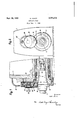
- FIGURE 1 is a vertical cross-sectional view through a part of the headstock of the machine tool according to the present invention.
- FIGURE 2 is a front elevational view of the headstock of FIGURE 1.
- reference numeral 2 designates therein the spindle which is rotatably mounted in any conventional manner within the headstock 1 of a machine tool.
- the spindle 2 is tapered internally at 4 for the purpose of centering the tool holder which in the instant case is the mandrel 6.
- the mandrel 6 is provided with an external taper 8 complementary to taper 4 and with a flange 10 absorbing or taking up the rotational forces.
- the axial groove 12 in the flange 10 and the block 16 secured within recess 14 of the spindle 2 serve for purposes of transmitting the rotational forces or torque between spindle 2 and mandrel 6.
- the mandrel 6 is provided at the rear end thereof with an externally threaded pin 18 which is adapted to be screw-threaded into the female thread provided in the draw rod 20 so that by tightening this screw-thread connection the mandrel 6 is pulled against the spindle 2 and is thereby centered with respect thereto.
- the securing or retaining disk 26 is rotatably mounted in the casing 22, which is detachably secured to the headstock 1 at the front end thereof, by means of the eccentric bearing pin 24.
- the disk 26 is secured against axial displacement with respect to casing 22 by means of the retainer disk 28, which is secured to the pin 24 in any suitable manner, for example, by means of screws or bolts 38 which are screwed into appropriate threaded bores provided in the rear part of pin 24 while casing 22 is removed from the headstock 1.
- the disk 26 is disposed a slight distance axially in front of the flange of the mandrel 6.
- the disk 26 is rotated about the axis of the bearing pin 24 until the overlap of the mandrel flange 10 by the disk 26 as this shown in FIGURE 2, becomes non-existent.
- the disk 26 is provided at its periphery with a knurled edge.
- the disk 26 is held in the rest or nonoperational position thereof by means of the springloaded detent pin 30 (FIGURE 2) and the recess 32 provided in the retainer disk 28.
- the rest position of the disk assembly 2628 is indicated in FIGURE 2 by the dot and dash line which is displaced by 180 with respect to the working position shown in full lines in FIGURES 1 and 2.
- the securing or retainer device according to the present invention may also be constituted within the scope of the present invention by a slide bar which is displaceable within a direction perpendicular to the spindle axis; in the alternative, the securing or retainer device can also be constituted by a hinged finger pivotally mounted on the headstock 1, for example to be pivotal about an axis parallel or perpendicular to the vertical plane passing through the spindle axis, and provided with suitable detent means for the operating and/ or rest position thereof.
- the advantage obtainable by the present invention with relatively small outlay and slight expense does not only consist in enabling a change of the tool holder in a more rapid manner and without the use of additional operating personnel or accessories, but, in particular, in the fact that the device is always available at the required place and does not need to be specially assembled or mounted for use whereby less time is spent on preparing for work without detracting from the required care in handling the tool holder.
- a device for use with machine tools which comprise at least one machine tool spindle rotatably mounted in a spindle carrier, said device serving operative to prevent mandrels, collets and similar tool holders from slipping out of the machine tool spindle when the screw connection with the draw rod for securing a mandrel or collet or similar tool holder within the spindle is ineffectual, comprising a tool holder, provided with flange means, a rotatable retainer disk, and means for rotatably and eccentrically mounting said disk on said spindle carrier within the region of said spindle so as to provide an overlap between a portion of said disk and said flange means in a first, working position of said disk in which the disk is located axially in front of said flange means at a small distance therefrom to prevent removal of the tool holder from the spindle and to enable rotary movement of said disk from said first, working position into a second, rest position in which said disk portion is moved out of the path of said flange means
- a device wherein the axis of rotation of said disk is disposed parallel and above the axis of said spindle in such a manner that said disk tends to assume said working position by virtue of its own Weight.
- a device further comprising detent means for securing said disk in said second position.
Landscapes
- Engineering & Computer Science (AREA)
- Mechanical Engineering (AREA)
- Automatic Tool Replacement In Machine Tools (AREA)
- Gripping On Spindles (AREA)
Applications Claiming Priority (1)
| Application Number | Priority Date | Filing Date | Title |
|---|---|---|---|
| DED29481A DE1090491B (de) | 1958-11-29 | 1958-11-29 | Vorrichtung fuer Werkzeugbefestigung |
Publications (1)
| Publication Number | Publication Date |
|---|---|
| US3055272A true US3055272A (en) | 1962-09-25 |
Family
ID=7040105
Family Applications (1)
| Application Number | Title | Priority Date | Filing Date |
|---|---|---|---|
| US853339A Expired - Lifetime US3055272A (en) | 1958-11-29 | 1959-11-16 | Machine tools |
Country Status (6)
| Country | Link |
|---|---|
| US (1) | US3055272A (de) |
| BE (1) | BE583915A (de) |
| CH (1) | CH374267A (de) |
| DE (1) | DE1090491B (de) |
| FR (1) | FR1241570A (de) |
| GB (1) | GB891661A (de) |
Cited By (4)
| Publication number | Priority date | Publication date | Assignee | Title |
|---|---|---|---|---|
| US3144736A (en) * | 1961-09-12 | 1964-08-18 | Freeman Supply Co | Spindle assembly |
| US4322190A (en) * | 1978-07-04 | 1982-03-30 | Sandvik Aktiebolag | Mounting device for machining tools |
| US5458603A (en) * | 1993-05-12 | 1995-10-17 | Futch, Sr.; William A. | Elongated drive tool for prosthesis in body cavity |
| US20010024402A1 (en) * | 1999-11-08 | 2001-09-27 | Japan Servo Co., Ltd. | Agitator and fixing device thereof |
Citations (3)
| Publication number | Priority date | Publication date | Assignee | Title |
|---|---|---|---|---|
| US1563070A (en) * | 1925-04-30 | 1925-11-24 | Huttig Mfg Co | Clamping device for combination storm and screen doors |
| US2583264A (en) * | 1945-08-27 | 1952-01-22 | Rigid Ltd | Chuck |
| US2685823A (en) * | 1951-02-24 | 1954-08-10 | Ingersoll Milling Machine Co | Mechanism for facilitating the detachable mounting of rotary devices |
Family Cites Families (1)
| Publication number | Priority date | Publication date | Assignee | Title |
|---|---|---|---|---|
| DE742877C (de) * | 1940-01-30 | 1943-12-13 | Hille Werke Ag | Vorrichtung zum Festziehen und Loesen von Werkzeugen mit kegeligem Schaft in einer kegeligen Laengsbohrung der Spindel |
-
1958
- 1958-11-29 DE DED29481A patent/DE1090491B/de active Pending
-
1959
- 1959-09-22 CH CH7854259A patent/CH374267A/de unknown
- 1959-09-29 GB GB32994/59A patent/GB891661A/en not_active Expired
- 1959-10-22 BE BE583915A patent/BE583915A/fr unknown
- 1959-11-16 US US853339A patent/US3055272A/en not_active Expired - Lifetime
- 1959-11-27 FR FR811435A patent/FR1241570A/fr not_active Expired
Patent Citations (3)
| Publication number | Priority date | Publication date | Assignee | Title |
|---|---|---|---|---|
| US1563070A (en) * | 1925-04-30 | 1925-11-24 | Huttig Mfg Co | Clamping device for combination storm and screen doors |
| US2583264A (en) * | 1945-08-27 | 1952-01-22 | Rigid Ltd | Chuck |
| US2685823A (en) * | 1951-02-24 | 1954-08-10 | Ingersoll Milling Machine Co | Mechanism for facilitating the detachable mounting of rotary devices |
Cited By (5)
| Publication number | Priority date | Publication date | Assignee | Title |
|---|---|---|---|---|
| US3144736A (en) * | 1961-09-12 | 1964-08-18 | Freeman Supply Co | Spindle assembly |
| US4322190A (en) * | 1978-07-04 | 1982-03-30 | Sandvik Aktiebolag | Mounting device for machining tools |
| US5458603A (en) * | 1993-05-12 | 1995-10-17 | Futch, Sr.; William A. | Elongated drive tool for prosthesis in body cavity |
| US20010024402A1 (en) * | 1999-11-08 | 2001-09-27 | Japan Servo Co., Ltd. | Agitator and fixing device thereof |
| US6474863B2 (en) * | 1999-11-08 | 2002-11-05 | Japan Servo Co. Ltd. | Agitator and fixing device thereof |
Also Published As
| Publication number | Publication date |
|---|---|
| BE583915A (fr) | 1960-02-15 |
| FR1241570A (fr) | 1960-09-16 |
| CH374267A (de) | 1963-12-31 |
| GB891661A (en) | 1962-03-14 |
| DE1090491B (de) | 1960-10-06 |
Similar Documents
| Publication | Publication Date | Title |
|---|---|---|
| US2593706A (en) | Clamping device for machine tools | |
| US4468834A (en) | Cleaning apparatus for machine spindles | |
| US2970844A (en) | Tool holder-axial locking type | |
| US3679220A (en) | Quick change tool holder | |
| US2320360A (en) | Quick-change device | |
| US3999769A (en) | Tool holder for machine tools | |
| US2892480A (en) | Flaring tool | |
| US3927583A (en) | Apparatus for loading a workpiece into a rotating collet or chuck | |
| US3219355A (en) | Tool holder | |
| US3752595A (en) | Adapter for drill speeder | |
| US2429617A (en) | Work or tool holding fixture | |
| US3136563A (en) | Tool supporting adapter | |
| US3136217A (en) | Flanged tool adapter | |
| US2231252A (en) | Tool holder | |
| US2145091A (en) | Turning and slotting device for commutators, etc. | |
| US4167362A (en) | Multiple tool driving turret attachment | |
| GB2065001A (en) | A drill chuck | |
| US3718339A (en) | Workpiece stop assembly for contracting collet chucks | |
| US3396982A (en) | Chuck | |
| US3174168A (en) | Self-aligning tool holder | |
| US4939834A (en) | Machine tool with tool change mechanism | |
| US2749806A (en) | Tool spindle mechanism | |
| US3189923A (en) | Thread cutting tool holder supported by turret type lathe | |
| US3676120A (en) | Side operated drawbolt for tool-carrying spindle | |
| US3334671A (en) | Machine for screwing a threaded stud into a workpiece |