US3097789A - Accumulator readout device - Google Patents
Accumulator readout device Download PDFInfo
- Publication number
- US3097789A US3097789A US781779A US78177958A US3097789A US 3097789 A US3097789 A US 3097789A US 781779 A US781779 A US 781779A US 78177958 A US78177958 A US 78177958A US 3097789 A US3097789 A US 3097789A
- Authority
- US
- United States
- Prior art keywords
- counting
- impulse
- impulses
- accumulator
- control elements
- Prior art date
- Legal status (The legal status is an assumption and is not a legal conclusion. Google has not performed a legal analysis and makes no representation as to the accuracy of the status listed.)
- Expired - Lifetime
Links
Images




Classifications
-
- G—PHYSICS
- G06—COMPUTING OR CALCULATING; COUNTING
- G06M—COUNTING MECHANISMS; COUNTING OF OBJECTS NOT OTHERWISE PROVIDED FOR
- G06M1/00—Design features of general application
- G06M1/08—Design features of general application for actuating the drive
- G06M1/10—Design features of general application for actuating the drive by electric or magnetic means
- G06M1/102—Design features of general application for actuating the drive by electric or magnetic means by magnetic or electromagnetic means
-
- B—PERFORMING OPERATIONS; TRANSPORTING
- B41—PRINTING; LINING MACHINES; TYPEWRITERS; STAMPS
- B41J—TYPEWRITERS; SELECTIVE PRINTING MECHANISMS, i.e. MECHANISMS PRINTING OTHERWISE THAN FROM A FORME; CORRECTION OF TYPOGRAPHICAL ERRORS
- B41J7/00—Type-selecting or type-actuating mechanisms
- B41J7/48—Type carrier arrested in selected position by electromagnetic means
-
- G—PHYSICS
- G06—COMPUTING OR CALCULATING; COUNTING
- G06M—COUNTING MECHANISMS; COUNTING OF OBJECTS NOT OTHERWISE PROVIDED FOR
- G06M1/00—Design features of general application
- G06M1/27—Design features of general application for representing the result of count in the form of electric signals, e.g. by sensing markings on the counter drum
-
- H—ELECTRICITY
- H03—ELECTRONIC CIRCUITRY
- H03K—PULSE TECHNIQUE
- H03K21/00—Details of pulse counters or frequency dividers
- H03K21/08—Output circuits
Definitions
- FIG. 10a AccuMuLA'roR READouT DEVICE Filed nec. 19, 195e 11 sheets-sheet a FIG. 10a
- the present invention refers to electronic calculating machines, and more particularly lto a method and apparatus for transferring numerical values accumulated in an electronic accumulator including at least one counting stage, to a mechanical counting, indicating or printing apparatus.
- the present invention applies to transferring the above mentioned numerical values from any types of an electronic accumulator in which at a given moment certain numerical values are stored and have to be transferred from this accumulator into apparatus of the type set forth.
- the numerical value is transmitted to the mechanical control elements only upon the tenth step (in a decimal counting system) from the counting stages of the electronic accumulator, which, in turn, entails the necessity that for the purpose of correctly printing the numerical values the individual type wheels must be shifted one step as compared with the ordinary and conventional construction and operation of ordinary printing apparatus, so that the otherwise conventional idle step is made ineffective.
- the otherwise conventional arrangements and structure of the mechanical control elements is specifically modified, then it is not possible anymore to use a standard keyboard or totalizing device of conventional office machines because in such machines it is common practice to arrange numerical values and to transfer them in the sequence from 0 to k9.5,
- lt is still a further object of this invention to provide a method and apparatus that would permit using an electronic accumulator arrangement alternatively either for counting or printing the actual values of certain numbers, or, in turn, print or count the complement values of said numbers.
- the method according to the present invention serves to transfer numerical values accumulated in van electronic accumulator including at least one counting stage, to a mechanical counting, indicating or printing apparatus having at least one set of incrementally movable digit-determining control elements capable of sequentially -assuming positions respectively associated with a series of digits forming part of a numerical value lto be indicated or printed, and mainly comprises the steps of first incrementally moving said set of control elements through said series of positions; simultaneously gener-ating a series of electric impulses respectively synchronous with the passing of sa-id control elements through said individual positions; injecting said electrical impulses sequentially into said accumulator for accordingly changing incrementally the numerical value stored therein before the start of the transferring operation and for causing said accumulator to furnish a control impulse when during said incrementally changing operation the counting capacity of said counting stages is exhausted; and arresting said set of control elements by means of said control impulse in the particular position occupied thereby at the time when said control impulse occurs.
- an arrangement for transferring numerical values accumulated in an electronic accumulator' including at least one counting stage, to a mechanical counting, indicating or printing apparatus having at least one set of incrementally movable digitdetermining control elements capable ⁇ of sequentially assuming positions respectively associated with a series of digits forming part yof a numerical value to be indicated or printed comprises, in combination, drive means for advancing said set of control elements incrementally through said sequence of positions; impulse generator means operatively connected with said set of control elements and capable of generating a sequence of counting impulses respectively synchronous with the passing of said set of control elements through said individual positions; circuit means connecting said impulse generator means with said counting stage for injecting said counting impulse into the latter; arresting means operatively connected with said set of control means, said arresting means being responsive to a contro-l impulse applied thereto and capable of arresting said set of control elements in any one of said positions Ithereof upon application of such a control impulse; and circuit means connecting said counting stage with said ⁇ arresting means and capable of transmit
- a preferred method for transferring accumulated multi-order numerical values from an electronic accumulator composed of a plurality of counting stages into a mechanical counting, indicating or printing apparatus mainly consists in a first step of injecting consecutively a plurality of series of simultaneous stepping impulses respectively into each of said stages for step-wise increasing the stored numerical values, the number of impulses constituting said individual series being predetermined for tobtaining at the end of at least one of such series a plurality of numerical values stored in said elements, respectively, which are respectively reduced by one numerical uni-t relatively to the respective values stored before injection of said particular series of impulses; a second step of preventing during the injection of each of said series of impulses the transmission of carry-over impulses upon exhaustion of the counting capacity of any one of said accumulator stages, except where such exhaustion of counting capacity occurs in any one of said elements upon the last impulse of the particular series of said stepping impulses; and a last step of transmitting Ito said mechanical ⁇ apparatus only such carryover
- a preferred arrangement for transferring multi-order numerical values from an electronic calculator or accumulator into a mechanical counting, indicating or printing apparatus mainly comprises a plurality of control elements moving step- Wise between consecutive digit-determining positions and forming part of said mechanical apparatus, each of said control elements being associated with one order uni-t of said apparatus and being capable of being arrested in any one of its digit-determining positions; an electronic accumulator means including a plurality of counting stages, gate means 'and locking magnet means respectively associated with each other for being capable of being actuated alternatively: for the oper-ation yof Iaccumulating multi-order numerical values in accordance with counting impulses injected into said accumulator means, tor for the operation of selectively arresting selected ones of said control elements in one of said positions by impulses emitted from respective counting stages into associated gate means and locking magnet means in accordance with series of consecutive impulses simultaneously injected into said counting units; shift register means including a plurality of counting stages and first impulse generator means and being capable of producing
- the intended result of restoring the stored digit value after a predetermined number of counting steps without having to carry ⁇ out the counting operation in reverse direction can be achieved by injecting into all units or counting stages of the electronic accumulator simultaneously series of consecutive impulses which are adapted to shift the stored values in positive or forward direction, in such a manner that at the termination ⁇ of each individual series of consecutive impulses, the values stored in the accumulator appear to be shifted in reverse direction; during this operation it is necessary to prevent carry-over operations from being effected between consecutive order units so that only those carry-over or transfer impulses are utilized for operating the mechanical apparatus, which have been caused by the last mechanical impulse of one particular series of impulses in a particular unit or Stage of the electronic accumulator.
- the present invention provides for a modification of the above outlined method in such a manner that with the iirst step of the control elements of the mechanical apparatus one ysingle series of ten impulses (in the case of a IO-digit numerical System) is injected simultaneously into all the counting stages of the accumulator, fand ⁇ only after this first series of ten impulses the above mentioned further ten series of 9 impulses each are injected.
- An eleventh step is provided in conjunction with a last series of 9 impulses although this step does not correspond to a step or movement of the control elements of the mechanical apparatus, but this ⁇ step is necessary for the purpose of restoring the originally stored numerical values in the various counting stages of the electronic accumulator. Now in this manner it is possible to transmit the regular lor actual numerical value of the stored numbers to the mechanical control elements of the mechanical apparatus without omitting the requirement of having the numerical value 0 transferred with the first step of the control elements.
- the mode of operation of the arrangement which carries lout the above-described function can be changed in a rather simple manner according to the invention for operating in such a way that the complement values of the originally stored numbers are transmitted.
- This change of operation is obtained by carrying out the read-out operation not by means of series of impulses but by injecting with every step of the control elements of the mechanical apparatus only one impulse into the electronic accumulator. In this case, with the iirst step of the control elements the complement value of 9 namely 0 is transmitted to the control elements of the mechanical apparatus.
- FIG. 1 is -a diagrammatic perspective view of one embodiment of the apparatus according to the invention.
- FIG. 2 is a similar perspective diagrammatic illustration of a modied embodiment of the apparatus according to the invention.
- FIG. 3 is a diagrammatic partial illustration of certain components characteristic of another embodiment of the invention.
- FIGS. 4 and 5 illustrate in front elevation and sectional end view, taken along lines V-V of FIG. 4, a component of the apparatus according to the invention
- FIGS. 4a ⁇ and 5a illustrate in front elevation and end view a modified form of the component illustrated by FIGS. 4 and 5;
- FIG. 6 is a diagrammatic perspective view of another form of a component of the apparatus according to the invention.
- FIG. 7 illustrates in diagrammatic and perspective manner still another modication of the component illustrated by FIG. 6;
- FIG. 8 is an enlarged plan view of an element of the component illustrated in FIG. 7; j
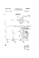
- FIG. 9 is a block diagram illustrating a preferred ernbodiment of the lapparatus according to the invention, this apparatus being suitable for deriving from a live-order electronic or magnetic accumulator the controls for a printing apparatus intended to reproduce the numerical value of numbers stored in the accumulator, as well as the complement values of those numbers;
- FIG. 10 is a diagrammatic perspective view of an apparatus according to the invention, including a printing mechanism and the circuit diagram of pertaining electric components.
- FIGS. 10a-10d are electric circuit diagrams of circuit components of counting devices showing their operative -connections wit-h the printing mechanism.
- the accumulator consists of -a plurality of interconnected counting stages, usually in a number equal to the number of orders of the numerical values to be handled.
- the numerical values may be of the type occurring in a decimal number system or in any other number system.
- the individual counting stage is capable of storing, for instance in a decimal number system, digits ranging from 0 to 9.
- the arrangement is analogous. In either case, the stored numerical value in each stage is changed by the injection of a counting impulse into that stage, 'and after the injection of a number of such counting impulses a situation will be reached in which the storage or counting capacity of the particular stage is exhausted.
- an impulse is emitted from the particular stage which is usually a so-called 0 impulse, also called a carry-over or resetting impulse.
- 0 impulse also called a carry-over or resetting impulse.
- the accumulator is used in the normal manner for accumulating values, the last mentioned 0 impulse is used to carry-over one numerical unit to the next Ifollowing counting stage of the accumulator. It is however necessary that in the case when values have lto be ltransferred from the accumulator to an indicating or printing mechanism the 0 impulse is not transferred or carried over to the neXt following counting stage but is used as a control impulse for inuencing the mechanical apparatus to which the above mentioned numerical values are to be transferred. A method and means for carrying out this utilization of O impulses in a transferring operation are described herebelow with reference to FIG. 9.
- a printing mechanisrn capable of handling ten-order numbers consists mainly of several type wheels 101 to 110, arranged for rotation about a common axle, not shown, the -aXis of which is indicated at 100.
- the type wheels are driven in known manner, via intermediate gears, by toothed bars 111 or 120, respectively, the so-called type wheel driving bars.
- Each type wheel with its associated intermediate gears and the pertaining driving bar constitutes one set of control elements of the mechanical apparatus in question. It is evident that the type wheels and gears are supported for rotation, ⁇ and that the driving bars are guided for movement in longitudinal direction Within a lframe-work not shown.
- the individual driving bars 111 to 120 are continuously urged by springs for movement in the direction of the arrow B.
- each of the driving bars has a slot parallel to the forward toothed section thereof and ya common collecting bar 131 is passed through all of the slots of all the driving bars 111 to 120. In the position shown which is not the position of rest of the whole arrangement the movement of the driving bars is stopped by the collecting bar 131 abutting against the rearward end of the slots of the bars.
- the collecting bar 131 is moved in the direction of the arrow B by means of a drive motor 132 which via intermediate gears moves a toothed bar 131a, attached to the bar 131, in the direction of the arrow B. It is clear that as the bar 131a moves the driving bars 111 to 120 are in a position to ⁇ follow this movement under the action of the springs 121 to 130.
- the fbars 111 to 120l are each provided with stop teeth 133. Assuming that the mechanism is to be used for handling numerical values ybelonging to a decimal number system so that the type Wheels 101 .to 110 carry each the 10 digit symbols ⁇ from 0 to 9, the number of stop teeth 133 is ten.
- each of the driving bars 111 to 120 has associated therewith arresting means comprising a pawl 134 movable in substantially vertical direction so as to be capable of engaging any one of the teeth 133 of the associated driving bar.
- the pawl 134 is associated with the bar 111 and similarly .the other pawls are associated with the other bars, the last pawl 143 being associated with the bar 120.
- the various pawls .134 to 143 are respectively under the inuence olf pawl springs 134 to 143', respectively, which tend to pull the respective pawls into engagement with the teeth 133.
- the arresting means further comprise for each one combination of a pawl and driving bar, a locking magnet 144 to 153, respectively, which when energized is capable o-f interrupting, by the .attraction of its armature, the holding engagement between the corresponding holding pawl and the associated pawl.
- the accumulator from which the numerical values are to be transferred tothe printing apparatus is diagrammatically indicated -by three counting stages 154, 155, 156 forming part of the whole accumulator comprising a series of such counting stages 154 to i163.
- the control impulses required for energizing the various locking magnets 144 to 153 are derived from the associated counting stages of the group 4154 to 163, respectively.
- electric impulses must be -injected into the accumulator in such a manner that the numerical values stored in the respective counting .stages are incrementally changed by a series of consecutive impulses, ten impulses in the present example, and which are generated by impulse generator means operatively connected with the printing apparatus.
- Accumulators of this general type are well known and usually composed of counting stages comprising each an electronic ⁇ decimal counting tube, e.g., the type known as Philips EIT.
- the impulse generator means mainly consists of a generator bar 16-4 which is connected with the collect-ing ⁇ bar 131 so as to move together with the latter under the driving action of the motor 132 as explained above.
- the generator bar 164 is provided with a series of cam portions 1164', ten .in number in this particular case, and a stationary pair of resilient contacts 174, the lower contact being equipped with a teeler piece A1'74 which slidingly travels over the consecutive cam portions 164.
- AIt . therefore clear that as the generator bar 164 moves in the direction of the arrow B the contact pair -174 is moved into conductive position everytime when the feeler 174' rides on the crest of one of the cam portions 164.
- the spacing between the individual cam portions 164 is such that the contact closing occurs everytime when during the rotation of the type wheels 1161 to one of the numerals arranged thereon is in indicating position, or, which means the same, anyone of the teeth 133 of any one of the bars is in register with the associated pawl .134 to 143, respectively.
- the accumulator is assumed to contain therein an accumulated or stored numerical value. Therefore the injection of the consecutive impulses created by the generator means as described, will change the numerical value stored in each one of the .counting stages of the electronic accumulator so that, depending upon the composition of the numerical value initially stored therein, at certain times the counting capacity of one or the other counting stage will 4be exhausted so that then the so called O ⁇ impulse is emitted from the particular lcounting stage where this exhaustion of storage or counting capacity occurs.
- the entire ten-order number can be printed from the type wheels, for instance by swinging the type Wheels -onto a platen in known manner.
- the toothed bars lll to 120 and simultaneously the type wheels 101 to 110 are returned to their initial positions, respectively, by reversing the driving direction of the motor 132.
- the pawls 134 to 143 are returned to their normal position in a way known generally in the art and therefore not requiring 1a detailed description.
- FIG. 2 generally resembles the embodiment described with reference to FIG. l. Therefore all those parts which are equal or equivalent to the components of the embodiment of FIG. 1 are designated by the same numerals except that the individual numeral is increased by 100. Therefore, e.g., the first driving bar marked 111 in FIG. l is identied by the numeral 211 in FIG. 2. The design of the pawls 234 slightly differs from that of the pawls 134 in FIG.
- FIG. 3 serves to move the type wheels in a somewhat different manner into their indicating or printing positions in accor-dance with a regular, non-complementary counting procedure.
- the parts shown in FIG. 3 and corresponding or being equivalent to those shown in FIGS. 1 and 2 are designated by numerals which diier from the numerals used in FIG. l by the addition of 200.
- the driving bars in FIG. 3 corresponding to the driving bars '111 to 1Z0 in FIG. l, are indica-ted by numerals 311 to 320.
- every one of the driving bars 311 to 320 carries on one side a contact bar 364 connected to a source of electrical energy and Ibeing provided with projecting contact points 364 spaced from each other in the same manner as the cam portions 164 in FIG. 1.
- a stationary pickup contact 374 is so positioned that during the travel of the bars 311 to 320 the respective contact points 364 -will consecutively pass by and engage the stationary contact 374 whereby a circuit through an impulse forming stage 384 is closed from where the impulse generated by the closing of the contact between the elements 364 and 374 is injected into the associated one of the counting stages 354 to 363, respectively, ⁇ of the per-taining electronic accumulator.
- rl ⁇ hc control impulse derived from the individual counting stage is transmitted to the associated electro-magnet 34d to 353, respectively, which in turn actuates the type wheel arrangement.
- energization of one of the magnets 344 to 353 will cause the intermediate gears of the associated type wheel 301 to 310 to be pulled in direction of the arrow Z into engagement with the corresponding teeth 335 of the associated driving bar. Consequently as the movement of the particular driving bar under the drive of the motor 332 proceeds after the electromagnet has caused the engagement between the type wheel arrangement and the particular driving bar, the respective drive wheel will be turned into a position which corresponds to the amount of travel of the particular driving bar after the above mentioned moment of engage-ment.
- the individual type Wheels will be positioned in such a manner that in the course of the movement of the pertaining drive bars the individual type wheels are in the desired indicating or printing position. Then, if desired, the printing operation can be carried out as mentioned above.
- the engagement between the type Wheel arrangement and the driving bars is eliminated as the electromagnets are cle-energized, so that the type Wheels as well as the driving bars can be returned to their starting or 0 position in a generally known manner, particularly the latter by reversing the direction of rotation of the motor 332.
- this control impulse is otiset in time by one impulse against the regular numerical value stored in the particular 1counting stages, it is necessary to suppress one step of the step-wise or increm-ental movement of the driving bars. For this reason, an arrangement ⁇ can be made for the driving bars to be in their normal or starting position one step backward as compared with the position used in the above described embodiments.
- the driving bars when in position of rest are in such a position that they have to make at least one step in order to get into the position corresponding to the value of 0 associated with the corresponding 0 position of the associated drive Wheel.
- impulse generator means fundamentally solve the problem of generating impulses synchronously with the stepwise or incremental movement ofthe drive bars
- the particular arrange-ments shown and described could cause disturbances or failure 4because the rapidly operated contacts 174, 274 or 3x74, may tend to bounce so that the disturbing consequences of such bouncing would have to be suppressed by means of special switching devices or methods.
- the use of metallic contacts could cause other diilculties due to changes in the contact resistance for instance due to oxidation or contamination of the contac-t tips.
- One suitable way is to generate the electrical impulses by magnetic means.
- FIGS. 4, 5 and FIGS. 4a, 5a Two modifications of such a magnetic impulse gener-ator are illustrated by FIGS. 4, 5 and FIGS. 4a, 5a.
- a generator bar 489 is used instead of the generator bar 164.
- the ybar 439 consists of ferro-magnetic material and is provided with a series of notches delining between each other pole tips 489. Preferably, the anks of the notches are lformed in accordance with an exponential curve.
- a C-shaped magnet struc- Iture, preferably including a permanent magnet portion 488 is positioned so that the bar 489 can be moved along a slot in the lower portion of the magnet frame y4% as can be seen in FIG. 5.
- the opposite end of the C-shaped frame 486 terminates in a similar pole tip 485.
- the vbar 489 if moved in longitudinal direction along the slot of the magnet will pass through a sequence .of positions in which the pole tip 486' is opposite one of the notches, and through positions where the stationary -pole tip 436 is in register with one ofthe pole tips 489 of the bar. It is therefore evident that every time when pole tips are in register with each other as just stated, the magnetic flux in the magnet is at a maximum while it is substantially reduced while one of the notches is opposed to the tip 486.
- a coil 487 is mounted around the yoke portion of the magnetic frame 486. Therefore the various changes of ux in the magnet are bound to induce electric impulses in the coil 487 which can then be used as electrical impulses to be injected into the accumulator.
- FIG. 4 shows that the spacings between consecutive pole tips 489 of the generator bar 489 are not equal. For instance at the right hand end of the bar 489 the spacing a0 is considerably smaller than the spacing a9 ⁇ at the left hand end of the bar. It is of quite some importance in many cases to space the pole tips 489 not equi-distantly for the following reasons.
- This ⁇ delay factor may be taken care of by correspondingly offsetting the generator bar
- the speed of movement ⁇ of the associated driving bars necessarily will increase from 0 to a certain maximum, thus the time required for the individual driving bars to move between say the position l and Z will be different from the time required to move between the positions 5 and 6.
- the different spacing of the pole tips 439 will compensate for the differences in the moving speed of the associated driving bar.
- the arrangement may have to be modified, for instance if the movement of the driving bars is not only accelerated after the start ⁇ but is decelerated after reaching a Imaximum and before the bar comes to -a full stop. In that ⁇ case the non-equidistant spacing between the pole tips 489 can be chosen accordingly.
- FIGS. 4a and 5a A modified version of the magnetic impulse generator of FIGS. 4 and 5, is illustrated by FlGS. 4a and 5a: in this case the magnet frame 486'" does not carry a coil in ⁇ which electrical impulses aire induced.
- the generator bar 489 is not shown in FIGS. 4a and 5a because it can be used in the same manner also in this modified version of the magnet impulse generator.
- the induction coil 487 is not used in this modified version because evidently the induced impulse depends also upon the speed of the movement of the bar 4S@ ybecause the speed of change of the magnetic flux controls the induction of electric current in the coil.
- 4a and 5a is based on the fact that the electric resistance of certain semi-conducting matemal-s as for instance bismuth, germanium, and especially that of AIHBV compounds, as for instance indium antimonide depends on the force of the surrounding magnetic iield. Based on this fact, a small plate 4.26" .preferably of indium antimonide is arranged according to the invention on the pole tip 436 as can be rseen FIGS. 4a, 5a.
- a very substantial impulse can -be tapped off the load 487 when the generator bar 489 is moved through the slot of the magnet yoke 486, 483.
- FIGS. 6 to 8 illustrate two versions of this type of impulse generator means.
- a generator bar 589 may be used instead of any 'one of the other generator bars described above.
- the bar 539 is provided with a series of slots S39' which are not equidistantly spaced from each other for the reasons stated above.
- the bar 539 is arranged to move in such a manner that the individual slots 589 consecutively pass across a :beam of light 600' furnished by a light source oli@ and directed at a photo electric cell 6%. It is evident that every time when one 13 of the slots passes through the beam of light 600 an impulse lwill tbe generated in generally known manner by the photo cell 6504i". This impulse can then be used as the electrical impulse to be injected into the electronic accumulator'.
- a generator bar 689 which has a set of gear teeth 639'. These teeth mesh with a small gear 69o mounted on a shaft which carries a disc 691 provided with a number of slots 69T. As can be seen the slots 691 are circumferentially spaced from each other non-equidistantly for the same reasons which have been explained above. It is evident that by moving the generator bar 689 conjointly with any one of the drivin-g bars the disc 691 will be caused to rotate.
- the disc 691 is so located that the slots 691 ccnlsecutively .pass across the beam of light 690 coming from the source of light 60u and directed at a photo electric cell 600". In the same manner as in the example illustrated by FIG. 6 the passing of any one of the slots through the beam will cause the generation of an impulse in the cell 6W" which impulses are then fed into the electronic accumulator as described above.
- FIGS. 1 and 4-8 can be advantageously combined with the method and apparatus described with reference to FIG. 9.
- the advantage is obtained that without changing the standard or conventional arrangement of the typ-e Wheel mechanism, the transferring operation concerning certain numerical values stored in the electronic accumulator can be carried out in a simple manner in two alternative Ways, namely either in such a manner that the numerical values stored initially in the electronic accumulator are made to appear in the type wheel mechanism in the same form or in the form of the complementary values based on that initially stored numerical value.
- An electronic accumulator 1li adapted to handle five-order numbers of a iti-digit number system ⁇ comprises five counting stages or order units indicated by numbers 11-15.
- An impulse forming device 4 is provided tor receiving from a suitable source counting impulses and for transmitting them into the accumulator lo.
- Impulse forming devices are known, eg., in the form of a monovibrator which upon application of a counting impulse delivers to the electronic accumulator or counter a precisely dened impulse of predetermined amplitude 14 and duration.
- Such impulse forming devices are dcscribed, eg., in Waveforrns, published 1949 by McGraw- I-Iill Book Co., Inc., in section 5.5, pages 16S-171.
- the impulse forming device @i and the individual counting stages 2li-15 are interconnected by a plurality of switches 51-55. When these switches are in open position as shown, then it is impossible for counting impulses to reach any one of the counting stages 11 to 15 or for any one oi these stages to transmit carry-over impulses from stage to stage.
- the individu-al counting stages 11-15 are connected with .a common line 10a which will be described later.
- every one of the counting stages il-l is associated with a locking magnet 33t-3S, respectively, adapted to arrest lthe corresponding control elements of the associated order unit of the mechanical printing or indicating apparatus, respectively, as described above in reference to FIGS. 1, 2 and 3.
- interposed between each of the counting stages 11-15 and the associated locking magnets 31-3S, respectively are gate circuits 21-25, respectively, which, depending upon their blocking or non-blocking condition will open or close a path between the individual counting stage and the associated locking magnet.
- Every one of the gate circuits 21-25 has a control input and all oi Ithese inputs vare connected to a common supply line lub.
- a switch '73 at one end of the line 10b is arranged for providing the line 10b with potential from either one of two different sources as will be explained further below.
- the accumulator is adapted to perform in two different Ways. It may be operated as an accumulator for accumulating numerical values stored in the various counting stages 1145. In this case, counting impulses are injected into the impulse transforming device 4 while all the switches Sil-55 are in closed position. At the same ltime the switch 73 is in the position shown in the drawing in which case the line 10b is connected with a source of potential feeding a negative voltage of l() volts into the gate circuits 21a-25 with the resuit that all these gates are caused to be in blocking condition so that the carry-over impulses occurring in the accumulator i@ are unable to cause any effect on the locking magnets 31-35.
- the accumulator 1t) can however be operated in a second manner in which case all the switches 51-55 are moved into open position and the switch 73 is moved into the position in which the source of supply mentioned above is disconnected from the gate circuits.
- the line 1Gb is now connected with the line 71a which will be explained further below.
- the ywhole arrangement is adapted for transferring any numerical value-s stored in the counting stages 11-15 into the mechanical apparatus connected therewith, or more specifically the control elements of the respective or asy sociated order units of that apparatus.
- An impulse generator means '72 is associated and operatively connected with the control elements of the mechanical apparatus.
- the function of that impulse generator is such that with every step of the step-wise moving control elements (as shown diagrammatically next to magnet 31 in FIG. 9) of any one of the order units of the mechanical apparatus, one impulse is generated in the impulse generator 72.
- this impulse generator 72 may be a photo-electric impulse generator device of the types described above in reference to FIGS. 7 and 8 and as shown next to bloc!L '72 in FIG. 9, and with every step of the type wheels a change in the illumination of the photo-cell may be produced thus generating a corresponding impulse.
- the control impulses from the generator 72 are applied to the rest of the arrangement by means of a selector switch 7S with which the generator 72 is connected.
- selector switch 78' can be moved between two positions, preferably mechanically, one position being used when the true or regular numerical values are to be transmitted to the mechanical apparatus from the accumulator 10, the other position being used when the complement values of the stored values are to be transmitted to the mechanical apparatus.
- the switch 7 8 opens a gate 77, while in the second case the gate 76 is opened.
- the gate 76 is connected by a conductor 76a and via a diode 76b to an impulse forming device y63 the output of which is connected with the above mentioned supply line 10a of the accumulator. The operation of this particular circuit will be described further below.
- the gate 77 is connected with another switching means which may consist of a flip-flop device 711 which is capable of assuming two stable positions depending upon impulses injected into the flip-flop.
- the ip-flop 71 has one input connected with the gate 77 and a second input connected with a generator 64 described further below.
- the flipflop has two outputs, one of which ⁇ is connected by the conductor 71a to the above-mentioned switch 73.
- the other output leads to a multi-vibrator 70 which in turn is connected with a shifting impulse generator 75 which may be of any conventional type capable of responding to an input impulse by delivering a shifting impulse and which serves to inject shifting impulses into a shift register 61 composed of counting stages 610-619;
- the individual counting stages 610-619 are respectively connected with a common conductor 69 which leads to delay circuit 62 and from there through a second diode 62a to the abovementioned impulse forming device 63.
- the register 61 serves as a read-out device and has ten elements.
- the register 61 is constructed in a generally known manner as a chain of magnetic counting stages having each a single coil.
- the auxiliary generator 68 is actuated by mechanically closing the starting switch 74 so that the first stage 610 of the register 61 can be pre-energized by the generator 68.
- the magnetic condition of the first stage 610 is changed by the impulse coming from the generator 68.
- the magnetic condition of the first stage 610 is now shifted in a generally known manner in ten steps from the stage 610 to the stage 619 o-f the register 61.
- the flip-flop 71 Since the switch 73 is, as mentioned above, now in its lower position connecting line 10b with line 71a, the flip-flop 71 is capable, during the time when the above mentioned shifting impulses are delivered to the register 61, to apply a suitable voltage to the gates 21-25 so that these gates are changed to their blocking position whereby any carry-over pulses from any one of the stages 11-15 are prevented from reaching fthe respectively associated locking magnets 31-35.
- the last shifting impulse of the register 61 derived from the last stage 619, reaches via the above-mentioned line 61a the flip-flop 71 whereby the flip-flop is caused to swing into its opposite stable condition so that now the gates 21-25 obtain a voltage by which they are changed back into unblocking condition.
- the last impulse emanating from the stage 619 travels via the auxiliary impulse generator 64 and line 64a to a second input of the second stage 611 of the register 61.
- the magnetic condition of this stage is changed whereby the register 61 is prepared for the arrival of the next impulse coming from the impulse generator 72.
- this impulse arrives via gate 77 at the llip-op 71 and again changes the condition of the latter so as to permit passage of this impulse to the multi-vibrator 70 with the result that again a shifting impulse is injected into the register 61.
- the impulse generator 72 has to function in synchronism with the stepwise movement of the control elements of the mechanical apparatus or with the stepwise movement of the type wheels of the printing apparatus, details of which are explained and described above, it is to be mentioned here that the required eleventh impulse is to be supplied to the Hip-flop 71 from a source A, not described in detail in this specification, but which may be any suitable impulse source that may be connected with the present arrangement and may be mechanically actuated at the termination of the ten steps of the control elements of the mechanical apparatus. For instance, this impulse may be released simultaneously with the return movement of the control elements or type bars into their original position after the completion of the ten forward steps thereof.
- the eleventh impulse injected into fthe flip-flop 71 operates exactly as the previous impulses furnished by the impulse generator 72 so that an eleventh sequence of nine limpulses are produced in and furnished by the shift register 61.
- the ip-iiop 71 must be actuated before the start of this operation of the arrangement by a preliminary impulse in such a manner that the gates 21-25 are in non-blocking condition,
- This primary or preparatory impulse is furnished to the flipflop 71 by operation of a separate switch 74 which may be operated by suitable mechanical means and maintains the applied voltage yin the ilip-op 71 in such a manner that the gates ZI-ZS remm'n in their non-blocking condition throughout the operation of the arrangement.
- the .arrangement according to the invention vintroduces the advantage that in either case the Value 0 is transmitted to the mechanical yapparatus talready with the iirst step of the control elements thereof.
- the time delay occurring between .an impulse fur-nished by ythe impulse generator 72, and the lcorresponding actuation of one or more of the locking magnets 31-35 can in no case amount to more than the time required yfor a sequence of 10 pulses. This is already the most unfavorable case. Assuming a pulse ifrequency of the multi-vibrator 70 of l() kilocy-cles the delay cannot amount to more than one msec. This delay is very well compatible with the requirements existing in the operation of a mechanical indicating or printing apparatus.
Landscapes
- Physics & Mathematics (AREA)
- Electromagnetism (AREA)
- General Physics & Mathematics (AREA)
- Engineering & Computer Science (AREA)
- Theoretical Computer Science (AREA)
- Character Spaces And Line Spaces In Printers (AREA)
- Inking, Control Or Cleaning Of Printing Machines (AREA)
- Displays For Variable Information Using Movable Means (AREA)
Description
July 16, 1963 M. KASSEL ETAL ACCUMULATOR READOUT DEVICE Filed Dec. 19, 1958 11 Sheets-Sheec l July 116, 1963 M. KASSEL Ez'rAl. 3,097,789
ACCUMULATOR READOUT DEVICE Filed Deo. 19, 1958 l1 Sheets-Sheet 2 July 16, 1963 M. KASSEL. r-:TAL 3,097,789
` ACCUMULATOR READOUT DEVICE Filed Dec. 19, 1958 1l Sheets-Sheet 3 .iff-.320
July 16, 1963 M. KASSEL ETAL 3,097,789
ACCUMULATOR READOUT DEVICE Filed Dec. 19, 1958 11 Sheets-Sheet 4 F7C-. 4a
4 i M l /MPULS'E July 16, 1963 Filed Dec. 19, 1958 M. KASSEL ETAL ACCUMULATOR READOUT DEVICE l 11 Sheets-Sheet 5 July 16, 1963 M. KASSEL ETAI.
AccUMuLAToR READOUT DEVICE July 16, 1963 M, KASSEL ETAL 3,097,789
ACCUMULATOR READOUT DEVICE:`
Filed Dec. 19, 1958 11 SheebS-Shle '7 Q u .Adair/L 5- S751 U- j Miam? July 16, 1963 M. KASSEL ETAL 3,097,789
AccuMuLA'roR READouT DEVICE Filed nec. 19, 195e 11 sheets-sheet a FIG. 10a
July 16, 1963 M. KASSEL ETAL 3,097,789
ACCUMULATOR READOUT DEVICE Filed Dec. 19, 1958 l1 Sheets-Sheet 9 July 16, 1963 M. KASSEL ETAL ACCUMULATOR READOUT DEVICE 11 Sheets-Sheet 10 Filed Dec. 19, 1958 dbx July 16, 1963 M. KASSEL ETAL AccuMuLAToR READouT DEVICE 11 Sheets-Sheet 11 F'iled Dec. 19, 195.8
xubx .l
Il! UQ 3,697,789 ACCUMULATR READOUT DEVICE Martin Kassel, Grafeliing, near Munich, and Gnter Martens, Schliersee, Upper Bavaria, Germany, assignors to Kienzle Apparate G-mbll., Villingen, Black Forest,
Germany Filed Dec. 19, 1958, Ser. No. 781,779 Claims priority, application Germany May Z1, 1955 25 Claims. (Cl. 2355-61) The present invention refers to electronic calculating machines, and more particularly lto a method and apparatus for transferring numerical values accumulated in an electronic accumulator including at least one counting stage, to a mechanical counting, indicating or printing apparatus.
More broadly, the present invention applies to transferring the above mentioned numerical values from any types of an electronic accumulator in which at a given moment certain numerical values are stored and have to be transferred from this accumulator into apparatus of the type set forth.
The present application is a continuation-impart of the copending application Serial No. 585,866, filed May 18, 1956, now abandoned, entitled Process for Transferring Values Contained in Electronic Counters to Mechanic Counters and/or Printing Devices.
It has been found that known apparatus or methods for transferring numerical values from electronic counting devices or accumulators into mechanical counters, indicating or printing apparatus are comparatively involved and cannot be satisfactorily operated in connection with various types of electronic counting apparatus. This is particularly .true Where the electronic counting device yor accumulator is for instance composed of magnetizable 4elements arranged as counting stages.
ln calculating machines equipped with such an electronic accumulator operating only in one direction with increasing digit values and comprising particularly a plurality of counting stages, or magnetic counting rings, it has only been possible up to now to transfer to the mechanical counting, indicating or printing apparatus the complement value of the stored number or digit. Therefore, if the regular or original value of the stored number `or digit had to be printed or indicated, it was necessary to translate the complement value position of the digit-determining control elements of said mechanical apparatus so as to indicate or print the regular number or digit value, for instance by providing the indicator or printing means, e.g., the types of the individual printing wheels, with a sequence of number types which are arranged in reversed direction. Wherever this old system has been applied, the numerical value is transmitted to the mechanical control elements only upon the tenth step (in a decimal counting system) from the counting stages of the electronic accumulator, which, in turn, entails the necessity that for the purpose of correctly printing the numerical values the individual type wheels must be shifted one step as compared with the ordinary and conventional construction and operation of ordinary printing apparatus, so that the otherwise conventional idle step is made ineffective. However, if the otherwise conventional arrangements and structure of the mechanical control elements is specifically modified, then it is not possible anymore to use a standard keyboard or totalizing device of conventional office machines because in such machines it is common practice to arrange numerical values and to transfer them in the sequence from 0 to k9.5,
It has been discovered that all the above difficulties and drawbacks could be avoided if a method or apparatus CTI 3,097,789 Patented `Iuly 16, 1963 could be `found for carrying out the read-out operation in such a system in the individual decimal orders of the units of the electronic accumulator during the printing operation, in reverse sequence. If this were done then the numerical value 0 would appear at the first step of the control elements of the printing apparatus and the actual or regular numerical value of the counted or stored value would be transferred tothe mechanical control elements instead of the complement value thereof. Attempts to redesign particularly the magnetic counter elements in such a manner as to count in reverse sequence have resulted in only extremely involved and complicated arrangements so that generally systems or apparatus of this type have not `found their Way into practical use. It should be noted that in this known method of counting in reverse sequence or direction the individual numerical value stored in one order unit of an electronic accumulator is reduced every time by means of a subtractively acting stepping impulse, each such impulse causing a reduction tof the stored value by a numerical unit 1. After carrying out ten such subtractive counting steps the particular counting stage is then restored to its condition corresponding to the originally sto-red value.
It is therefore a main object of the present invention to provide for a method and an apparatus for transferring numerical values accumulated in an electronic accumulator including at least one counting stage, to a mechanical counting, indicating or printing apparatus.
It is the further object of this invention to provide a method and apparatus of the type set forth which is particularly simple in design or execution, respectively, while at the same time being highly eiiicient and reliable.
It is another object of the present invention to establish a method and apparatus that would avoid all the difficulties described above and typical of the prior art and at the same time constitute a method and apparatus of comparatively simple type.
lt is still a further object of this invention to provide a method and apparatus that would permit using an electronic accumulator arrangement alternatively either for counting or printing the actual values of certain numbers, or, in turn, print or count the complement values of said numbers.
With above objects in mind, the method according to the present invention serves to transfer numerical values accumulated in van electronic accumulator including at least one counting stage, to a mechanical counting, indicating or printing apparatus having at least one set of incrementally movable digit-determining control elements capable of sequentially -assuming positions respectively associated with a series of digits forming part of a numerical value lto be indicated or printed, and mainly comprises the steps of first incrementally moving said set of control elements through said series of positions; simultaneously gener-ating a series of electric impulses respectively synchronous with the passing of sa-id control elements through said individual positions; injecting said electrical impulses sequentially into said accumulator for accordingly changing incrementally the numerical value stored therein before the start of the transferring operation and for causing said accumulator to furnish a control impulse when during said incrementally changing operation the counting capacity of said counting stages is exhausted; and arresting said set of control elements by means of said control impulse in the particular position occupied thereby at the time when said control impulse occurs.
In another aspect of this invention an arrangement for transferring numerical values accumulated in an electronic accumulator' including at least one counting stage, to a mechanical counting, indicating or printing apparatus having at least one set of incrementally movable digitdetermining control elements capable `of sequentially assuming positions respectively associated with a series of digits forming part yof a numerical value to be indicated or printed, comprises, in combination, drive means for advancing said set of control elements incrementally through said sequence of positions; impulse generator means operatively connected with said set of control elements and capable of generating a sequence of counting impulses respectively synchronous with the passing of said set of control elements through said individual positions; circuit means connecting said impulse generator means with said counting stage for injecting said counting impulse into the latter; arresting means operatively connected with said set of control means, said arresting means being responsive to a contro-l impulse applied thereto and capable of arresting said set of control elements in any one of said positions Ithereof upon application of such a control impulse; and circuit means connecting said counting stage with said `arresting means and capable of transmitting thereto said control impulse every time when during injecting said counting impulses the counting capaci-ty of said counting stage is exhausted.
In still another aspect of this invention, a preferred method for transferring accumulated multi-order numerical values from an electronic accumulator composed of a plurality of counting stages into a mechanical counting, indicating or printing apparatus, mainly consists in a first step of injecting consecutively a plurality of series of simultaneous stepping impulses respectively into each of said stages for step-wise increasing the stored numerical values, the number of impulses constituting said individual series being predetermined for tobtaining at the end of at least one of such series a plurality of numerical values stored in said elements, respectively, which are respectively reduced by one numerical uni-t relatively to the respective values stored before injection of said particular series of impulses; a second step of preventing during the injection of each of said series of impulses the transmission of carry-over impulses upon exhaustion of the counting capacity of any one of said accumulator stages, except where such exhaustion of counting capacity occurs in any one of said elements upon the last impulse of the particular series of said stepping impulses; and a last step of transmitting Ito said mechanical `apparatus only such carryover impulses which occur in any one of said stages upon said last impulse, for causing said apparatus to make appear multi-order numerical values corresponding in each of its orders to the numerical value whichbefore the start of the first of said plurality of series of stepping impulses was stored in thatt one of said counting stages in which said carry-over impulse occurred upon the last one of said stepping impulses of the particular series.
In a further aspect of this invention, a preferred arrangement for transferring multi-order numerical values from an electronic calculator or accumulator into a mechanical counting, indicating or printing apparatus, mainly comprises a plurality of control elements moving step- Wise between consecutive digit-determining positions and forming part of said mechanical apparatus, each of said control elements being associated with one order uni-t of said apparatus and being capable of being arrested in any one of its digit-determining positions; an electronic accumulator means including a plurality of counting stages, gate means 'and locking magnet means respectively associated with each other for being capable of being actuated alternatively: for the oper-ation yof Iaccumulating multi-order numerical values in accordance with counting impulses injected into said accumulator means, tor for the operation of selectively arresting selected ones of said control elements in one of said positions by impulses emitted from respective counting stages into associated gate means and locking magnet means in accordance with series of consecutive impulses simultaneously injected into said counting units; shift register means including a plurality of counting stages and first impulse generator means and being capable of producing said series of consecutive impulses upon receiving a first control impulse from said rst impulse generator means; second impulse generator means operatively connected with said control elements for furnishing with each step thereof a control impulse alternatively adapted to be injected into said electronic accumulator or said shift register means; `and a plurality of switch means respectively connected with said electronic accumulator and shift register means for changing said electronic accumulator means between said alternative modes of operation, and for Aalternatively connecting said second impulse generator means with said accumulator or with said shift register means.
It will be shown that in accordance with the invention the intended result of restoring the stored digit value after a predetermined number of counting steps without having to carry `out the counting operation in reverse direction, can be achieved by injecting into all units or counting stages of the electronic accumulator simultaneously series of consecutive impulses which are adapted to shift the stored values in positive or forward direction, in such a manner that at the termination `of each individual series of consecutive impulses, the values stored in the accumulator appear to be shifted in reverse direction; during this operation it is necessary to prevent carry-over operations from being effected between consecutive order units so that only those carry-over or transfer impulses are utilized for operating the mechanical apparatus, which have been caused by the last mechanical impulse of one particular series of impulses in a particular unit or Stage of the electronic accumulator. For instance, in the case of a decimal or ten-digit number system, the above-mentioned necessity of counting subtractively is avoided by injecting with every step of the control elements of the printing or indicating apparatus a series of 9 impulses additively into each counting element of the accumulator simultaneously. After l0 such steps of the control elements `of the mechanical apparatus a totai of 10X 9, i.e., 90 impulses have been totally injected into each individual counting stage of the accumulator, the carry-over impulses between the individual order units or elements of the accumulator being suppressed or eliminated every time the counting capacity of the individual counting stages is exhausted at the arrival at the numerical value l0, with the result, that at the end of the total operation the original numerical value that was originally stored in the electronic accumulator is restored therein. It can be seen that in accordance with this method, a stored numerical value in each individual counting stage is reduced by the numerical unit "l every time after the injection of one series of 9 consecutive impulses is completed. lt is further clear that during the injection :of each one of these series or 9 consecutive impulses, in each `order unit or counting stage of the accumulator one restoring impulse must appear. These restoring impulses can be used for energizing certain magnetic locking means which are intended to arrest the associated mechanical control means of the abovementioned apparatus in a certain position thereof. However of these restoring impulses `only those Aare permitted to energize or cause to energize a locking magnet which occur with the last impulse of such a 9-impulse series. This performance can be provided for by arranging between the individual counting stages of the accumulator and their respectively associated locking magnet means a gate device which is `open or in non-blocking condition only dur-ing the time period of the above-mentioned last impulse of one series.
It can further be seen that with the aid of the above described system a counting operation of the electronic accumulator in seemingly reverse `direction can be obtained without the necessity of reversing the direction of counting of the various counting stages or units of the accumulator. Yet there would remain still the difficulty that the numerical value "0 is transmitted to the control element of the mechanical apparatus only when the tenth step of the step-wise moving control elements of the printing apparatus occurs.
In order to eliminate Ialso this diiiiculty, the present invention provides for a modification of the above outlined method in such a manner that with the iirst step of the control elements of the mechanical apparatus one ysingle series of ten impulses (in the case of a IO-digit numerical System) is injected simultaneously into all the counting stages of the accumulator, fand `only after this first series of ten impulses the above mentioned further ten series of 9 impulses each are injected. By reading out the individual counting stages or order units of the electronic accumulator by means of a l0-impulse series the desired result is obtained, namely all the counting stages which did contain the stored numerical value 0 will now transmit this particular value to the control elements of the mechanical apparatus during the iirst step thereof, namely by means of arresting the particular control elements with the aid of the actuation of locking magnet means. From the same unit or counting stage of the accumulator the value "1 would be transferred upon the second step of the control elements by means of the next following series of 9 impulses, similarly upon the third step of the control elements the value 2 will be transmitted and so on until upon the tenth step of the control elements the numerical value 9 would be transmitted to the control elements. An eleventh step is provided in conjunction with a last series of 9 impulses although this step does not correspond to a step or movement of the control elements of the mechanical apparatus, but this `step is necessary for the purpose of restoring the originally stored numerical values in the various counting stages of the electronic accumulator. Now in this manner it is possible to transmit the regular lor actual numerical value of the stored numbers to the mechanical control elements of the mechanical apparatus without omitting the requirement of having the numerical value 0 transferred with the first step of the control elements.
The mode of operation of the arrangement which carries lout the above-described function can be changed in a rather simple manner according to the invention for operating in such a way that the complement values of the originally stored numbers are transmitted. This change of operation is obtained by carrying out the read-out operation not by means of series of impulses but by injecting with every step of the control elements of the mechanical apparatus only one impulse into the electronic accumulator. In this case, with the iirst step of the control elements the complement value of 9 namely 0 is transmitted to the control elements of the mechanical apparatus.
The novel features which are considered as characteristie for the invention are set yforth in particular in the appended claims. The invention itself, however, both as to its construction and its method of operation, together with additional objects and advantages thereof, will be best understood from the following description of specific ernbodiments when read in connection with the accompanying drawings, in which:
FIG. 1 is -a diagrammatic perspective view of one embodiment of the apparatus according to the invention;
FIG. 2 is a similar perspective diagrammatic illustration of a modied embodiment of the apparatus according to the invention;
FIG. 3 is a diagrammatic partial illustration of certain components characteristic of another embodiment of the invention;
FIGS. 4 and 5 illustrate in front elevation and sectional end view, taken along lines V-V of FIG. 4, a component of the apparatus according to the invention;
FIGS. 4a `and 5a illustrate in front elevation and end view a modified form of the component illustrated by FIGS. 4 and 5;
FIG. 6 is a diagrammatic perspective view of another form of a component of the apparatus according to the invention;
FIG. 7 illustrates in diagrammatic and perspective manner still another modication of the component illustrated by FIG. 6;
FIG. 8 is an enlarged plan view of an element of the component illustrated in FIG. 7; j
FIG. 9 is a block diagram illustrating a preferred ernbodiment of the lapparatus according to the invention, this apparatus being suitable for deriving from a live-order electronic or magnetic accumulator the controls for a printing apparatus intended to reproduce the numerical value of numbers stored in the accumulator, as well as the complement values of those numbers;
FIG. 10 is a diagrammatic perspective view of an apparatus according to the invention, including a printing mechanism and the circuit diagram of pertaining electric components.
FIGS. 10a-10d are electric circuit diagrams of circuit components of counting devices showing their operative -connections wit-h the printing mechanism.
The above listed illustrations will also serve to explain the method according to the present invention.
Electronic accumulators are well known in the art. If multi-order numerical values are to be handled, the accumulator consists of -a plurality of interconnected counting stages, usually in a number equal to the number of orders of the numerical values to be handled. The numerical values may be of the type occurring in a decimal number system or in any other number system. In any case the individual counting stage is capable of storing, for instance in a decimal number system, digits ranging from 0 to 9. In other number systems the arrangement is analogous. In either case, the stored numerical value in each stage is changed by the injection of a counting impulse into that stage, 'and after the injection of a number of such counting impulses a situation will be reached in which the storage or counting capacity of the particular stage is exhausted. When this occurs, which is usually the case when after the number 9 the 0 value is reached, an impulse is emitted from the particular stage which is usually a so-called 0 impulse, also called a carry-over or resetting impulse. When the accumulator is used in the normal manner for accumulating values, the last mentioned 0 impulse is used to carry-over one numerical unit to the next Ifollowing counting stage of the accumulator. It is however necessary that in the case when values have lto be ltransferred from the accumulator to an indicating or printing mechanism the 0 impulse is not transferred or carried over to the neXt following counting stage but is used as a control impulse for inuencing the mechanical apparatus to which the above mentioned numerical values are to be transferred. A method and means for carrying out this utilization of O impulses in a transferring operation are described herebelow with reference to FIG. 9.
Referring now particularly to FIG. 1, a printing mechanisrn capable of handling ten-order numbers consists mainly of several type wheels 101 to 110, arranged for rotation about a common axle, not shown, the -aXis of which is indicated at 100. The type wheels are driven in known manner, via intermediate gears, by toothed bars 111 or 120, respectively, the so-called type wheel driving bars. Each type wheel with its associated intermediate gears and the pertaining driving bar constitutes one set of control elements of the mechanical apparatus in question. It is evident that the type wheels and gears are supported for rotation, `and that the driving bars are guided for movement in longitudinal direction Within a lframe-work not shown. The individual driving bars 111 to 120 are continuously urged by springs for movement in the direction of the arrow B. This action is produced by springs 121 to 130 of which only two are shown and which are interposed between 'a portion A of the general frame and the rearward end of the individual driving bars. As can be seen in FIG. 1 each of the driving bars has a slot parallel to the forward toothed section thereof and ya common collecting bar 131 is passed through all of the slots of all the driving bars 111 to 120. In the position shown which is not the position of rest of the whole arrangement the movement of the driving bars is stopped by the collecting bar 131 abutting against the rearward end of the slots of the bars. When it is desired to operate the printing mechanism as described above, the collecting bar 131 is moved in the direction of the arrow B by means of a drive motor 132 which via intermediate gears moves a toothed bar 131a, attached to the bar 131, in the direction of the arrow B. It is clear that as the bar 131a moves the driving bars 111 to 120 are in a position to `follow this movement under the action of the springs 121 to 130.
The fbars 111 to 120l are each provided with stop teeth 133. Assuming that the mechanism is to be used for handling numerical values ybelonging to a decimal number system so that the type Wheels 101 .to 110 carry each the 10 digit symbols `from 0 to 9, the number of stop teeth 133 is ten.
As can be seen Ifrom FIG l, each of the driving bars 111 to 120 has associated therewith arresting means comprising a pawl 134 movable in substantially vertical direction so as to be capable of engaging any one of the teeth 133 of the associated driving bar. The pawl 134 is associated with the bar 111 and similarly .the other pawls are associated with the other bars, the last pawl 143 being associated with the bar 120. The various pawls .134 to 143 are respectively under the inuence olf pawl springs 134 to 143', respectively, which tend to pull the respective pawls into engagement with the teeth 133. However this movement is prevented by the engagement of holding pawls 134 to 143 with a corresponding notch in the lower part of the respective pawls 134 to 143. As shown in FIG. l the pawl 134 is held back in non-erigagement position by the locking pawl 134" against the action of the spring i134. The arresting means further comprise for each one combination of a pawl and driving bar, a locking magnet 144 to 153, respectively, which when energized is capable o-f interrupting, by the .attraction of its armature, the holding engagement between the corresponding holding pawl and the associated pawl. This means, that whenever one of the locking magnets 144 to 153 is energized .the associated pawl 134 to 143, respectively will be released so as to engage any one of the teeth 133 of the .associated driving bar -111 to 120 whereby the particular bar is arrested in that position which the particular bar .occupies lat the moment when the corresponding locking magnet is energized. In the position shown in FIG. l, the actuation of the magnet i144 would cause the pawl 134 to engage the Ifourth tooth 133 of the bar 111 which corresponds to a position of the type wheel 101 which would result in indicating .or printing the fourth numeral .arranged thereon, counting ifrom the numeral which is in indicating position rwhen the apparatus is in position of rest.
The accumulator from which the numerical values are to be transferred tothe printing apparatus is diagrammatically indicated -by three counting stages 154, 155, 156 forming part of the whole accumulator comprising a series of such counting stages 154 to i163. rThe control impulses required for energizing the various locking magnets 144 to 153 are derived from the associated counting stages of the group 4154 to 163, respectively. In order to obtain these control impulses from the electronic accumulator, electric impulses must be -injected into the accumulator in such a manner that the numerical values stored in the respective counting .stages are incrementally changed by a series of consecutive impulses, ten impulses in the present example, and which are generated by impulse generator means operatively connected with the printing apparatus. Accumulators of this general type are well known and usually composed of counting stages comprising each an electronic `decimal counting tube, e.g., the type known as Philips EIT.
In the example illustrated by FIG. 1 the impulse generator means mainly consists of a generator bar 16-4 which is connected with the collect-ing `bar 131 so as to move together with the latter under the driving action of the motor 132 as explained above. The generator bar 164 is provided with a series of cam portions 1164', ten .in number in this particular case, and a stationary pair of resilient contacts 174, the lower contact being equipped with a teeler piece A1'74 which slidingly travels over the consecutive cam portions 164. AIt .is therefore clear that as the generator bar 164 moves in the direction of the arrow B the contact pair -174 is moved into conductive position everytime when the feeler 174' rides on the crest of one of the cam portions 164. The spacing between the individual cam portions 164 is such that the contact closing occurs everytime when during the rotation of the type wheels 1161 to one of the numerals arranged thereon is in indicating position, or, which means the same, anyone of the teeth 133 of any one of the bars is in register with the associated pawl .134 to 143, respectively. This means that synchronously with the passing of the numerals on Ithe type wheels through the indicating positions thereof impulses are injected into the electronic accumulator stages 154- to 16H3 :by the consecutively repeating closing of the contact pair 174, on account of the circuit connection between these contacts, including a battery C and .conductors which permit tol inject each of said impulses simultaneously into all of the counting stages of the accumulator. As has lbeen explained above, the accumulator is assumed to contain therein an accumulated or stored numerical value. Therefore the injection of the consecutive impulses created by the generator means as described, will change the numerical value stored in each one of the .counting stages of the electronic accumulator so that, depending upon the composition of the numerical value initially stored therein, at certain times the counting capacity of one or the other counting stage will 4be exhausted so that then the so called O` impulse is emitted from the particular lcounting stage where this exhaustion of storage or counting capacity occurs. It is to be understood that provisions are made to prevent .these i0 impulses Ito act as carry-over or re-.setting impulses as in nor-mal counting procedure; instead these O impulses are then injected as control impulses through the connecting lines shown in FIG. 1 into the associated locking magnets 144 to 153, respectively. Consequently, whenever one of the driving bars 111 to i120 is stopped by one of Athose control impulses mentioned above the corresponding type wheel will be arrested in a position in which a numeral is `in indicating or printing position which is equal to the complement of the digit which was initialy stored in the associated counting stage of the accumulator. It can also Ibe seen, that no matter which one .of the various driving bars 111 to 121i has been stopped in the above described manner, the other bars are free to proceed in their movement in the direction of the arrow B until they are stopped in a proper position.
As a rule it is not desired that the type wheels are stopped in a position which makes the complement numbers to the stored numbers appear in indicating or printing position. Therefore it would be advisable to arrange the numerals on the type wheels in reversed order so that during their rotation they so-to-say count backwards. However, this can be avoided Iby other means. In the above description it has been assumed that the electrical impulses injected from the generator rmeans into the accumulator influence the latter in a forward counting manner, i.e., additively. If it is, however, desired to have the numerals on the type Wheels arranged in the normal way, that is in forward counting arrangement with respect to their direction of turn, then it is possible to arrange matters in such a manner that the electrical impulses furnished by the generator means .are injected into the electronic accumulator in backward counting sequence, i.e., subtractively. In this case the re-setting or O impulses will be delivered from the electronic accumulator or from the individual counting stage thereof at a moment when as many impulses have been injected into the accumulator as correspond to the regular numerical value of the igure to be indicated or printed, so that the type wheels will be arrested in positions which correspond to that regular numerical value and not to .the complement thereof.
In the present example, after the bar 13151 has been moved through a complete stroke which causes a sequence of ten control impulses to be generated by the generator means Cioe, 174, a sequence of ten impulses has been injected into all of the counting stages 154i to y163 of the accumulator so that the originally stored numerical value is reestablisbed ltherein. At the same time the originally stored numerical value has been completely transmitted to the series of type wheels 101 to 110. Each one of them is in a position in which each one of lthe digits forming the numerical values stored in the accumulator is represented in the same order sequence by identical numerals or complement numerals on the various type Awheels and each of tlhe respective numerals is now in indicating position. If desired, the entire ten-order number can be printed from the type wheels, for instance by swinging the type Wheels -onto a platen in known manner. I-Iereafter the toothed bars lll to 120 and simultaneously the type wheels 101 to 110 are returned to their initial positions, respectively, by reversing the driving direction of the motor 132. During the return movement of the driving bars also the pawls 134 to 143 are returned to their normal position in a way known generally in the art and therefore not requiring 1a detailed description. It may suice to state that the slanting portions of the teeth 133 will force down the associated pawl 134.- to M3, respectively, so that the associated holding pawl 13d to 143, respectively, will engage the holding notch of the corresponding pawl.
The modied embodiment illustrated by FIG. 2 generally resembles the embodiment described with reference to FIG. l. Therefore all those parts which are equal or equivalent to the components of the embodiment of FIG. 1 are designated by the same numerals except that the individual numeral is increased by 100. Therefore, e.g., the first driving bar marked 111 in FIG. l is identied by the numeral 211 in FIG. 2. The design of the pawls 234 slightly differs from that of the pawls 134 in FIG. l since `the pawl 234 is carried -by the rocker arm 23d, being under the action of a spring 234 tending to keep the pawl out yof engagement with the .teeth 233, while the opposite end of the rocker arm 234i" is connected to the armature of the corresponding one of the locking magnets 244 to 253, respectively. More important is the diiierence consisting in the fact that instead of one single generator bar 164 and one pair of contacts T74 connected jointly or in parallel with all of the individual counting stages 154- to 163, now everyone of the driving bars 2li to 220 is provided with a generator portion 264 to 273, respectively having -a series of cam portions 264 to 273', respectively, a pair of contacts 27d to 233, respectively, lbeing in operative connection with the above mentioned cam portions. Consequently each `one of the contact pairs 274 to 283, respectively, is individually connected with only one of the counting stages 25d to 263, respectively, associated therewith. It is readily understandable that the `operation of this arrangement is entirely analogous to that set `for-th labove with respect to the embodiment of FIG. l.
supplementing the above description of one embodiment of the invention and a modification thereof, an arrangement will now be described in reference to FlG. 3 which serves to move the type wheels in a somewhat different manner into their indicating or printing positions in accor-dance with a regular, non-complementary counting procedure. The parts shown in FIG. 3 and corresponding or being equivalent to those shown in FIGS. 1 and 2 are designated by numerals which diier from the numerals used in FIG. l by the addition of 200. For instance the driving bars in FIG. 3, corresponding to the driving bars '111 to 1Z0 in FIG. l, are indica-ted by numerals 311 to 320. However, in this case every one of the driving bars 311 to 320 carries on one side a contact bar 364 connected to a source of electrical energy and Ibeing provided with projecting contact points 364 spaced from each other in the same manner as the cam portions 164 in FIG. 1. A stationary pickup contact 374 is so positioned that during the travel of the bars 311 to 320 the respective contact points 364 -will consecutively pass by and engage the stationary contact 374 whereby a circuit through an impulse forming stage 384 is closed from where the impulse generated by the closing of the contact between the elements 364 and 374 is injected into the associated one of the counting stages 354 to 363, respectively, `of the per-taining electronic accumulator. rl`hc control impulse derived from the individual counting stage is transmitted to the associated electro-magnet 34d to 353, respectively, which in turn actuates the type wheel arrangement. As can be seen from FIG. 3 energization of one of the magnets 344 to 353 will cause the intermediate gears of the associated type wheel 301 to 310 to be pulled in direction of the arrow Z into engagement with the corresponding teeth 335 of the associated driving bar. Consequently as the movement of the particular driving bar under the drive of the motor 332 proceeds after the electromagnet has caused the engagement between the type wheel arrangement and the particular driving bar, the respective drive wheel will be turned into a position which corresponds to the amount of travel of the particular driving bar after the above mentioned moment of engage-ment. In this 'manner again the individual type Wheels will be positioned in such a manner that in the course of the movement of the pertaining drive bars the individual type wheels are in the desired indicating or printing position. Then, if desired, the printing operation can be carried out as mentioned above. Hereafter the engagement between the type Wheel arrangement and the driving bars is eliminated as the electromagnets are cle-energized, so that the type Wheels as well as the driving bars can be returned to their starting or 0 position in a generally known manner, particularly the latter by reversing the direction of rotation of the motor 332.
It should be noted that it is also possible to position the type Wheels for indicating or printing the regular numerical value initially stored in the accumulator, by having the electronic accumulator count backwards when supplied with the electrical impulses delivered by the impulse generator means operated by the type Wheel mechanism as described above. In -this case a resetting or 0 impulse is delivered every time 'when :the counting within one counting stage passes from the value 0 to 9, resul-ting in a resetting impulse which as stated above is used in the framework of this invention as a control impulse for stopping or arresting the control elements of the type wheel apparatus. Since for obvious reasons this control impulse is otiset in time by one impulse against the regular numerical value stored in the particular 1counting stages, it is necessary to suppress one step of the step-wise or increm-ental movement of the driving bars. For this reason, an arrangement `can be made for the driving bars to be in their normal or starting position one step backward as compared with the position used in the above described embodiments. In other Words, the driving bars when in position of rest are in such a position that they have to make at least one step in order to get into the position corresponding to the value of 0 associated with the corresponding 0 position of the associated drive Wheel.
It is to be mentioned at this instance, that the above mentioned requirement of eliminating the possibility of one counting stage, the storage or counting capacity of which has been exhausted, transferring the O impulses as a carry-over impulse into the next following counting stage of the accumulator, can Abe complied with very simply by arranging in the printing mechanism a suitable switch means which upon the start of the transferring operation interrupts the connections between the consecutive counting stages of the accumulator and instead, if necessary, establishes the connection between the counting stages and the arresting means.
While the above described examples of impulse generator means fundamentally solve the problem of generating impulses synchronously with the stepwise or incremental movement ofthe drive bars, it is Well possible that the particular arrange-ments shown and described could cause disturbances or failure 4because the rapidly operated contacts 174, 274 or 3x74, may tend to bounce so that the disturbing consequences of such bouncing would have to be suppressed by means of special switching devices or methods. Moreover, the use of metallic contacts could cause other diilculties due to changes in the contact resistance for instance due to oxidation or contamination of the contac-t tips.
In order to overcome these difliculties all metallic contacts land Itheir operation are advantageously eliminated by providing other means for generating the electric impulses required.
One suitable way is to generate the electrical impulses by magnetic means.
Two modifications of such a magnetic impulse gener-ator are illustrated by FIGS. 4, 5 and FIGS. 4a, 5a. Referring to FlGS. 4 and 5, a generator bar 489 is used instead of the generator bar 164. The ybar 439 consists of ferro-magnetic material and is provided with a series of notches delining between each other pole tips 489. Preferably, the anks of the notches are lformed in accordance with an exponential curve. A C-shaped magnet struc- Iture, preferably including a permanent magnet portion 488 is positioned so that the bar 489 can be moved along a slot in the lower portion of the magnet frame y4% as can be seen in FIG. 5. The opposite end of the C-shaped frame 486 terminates in a similar pole tip 485. As can be seen from FIGS. `4 and 5 the vbar 489 if moved in longitudinal direction along the slot of the magnet will pass through a sequence .of positions in which the pole tip 486' is opposite one of the notches, and through positions where the stationary -pole tip 436 is in register with one ofthe pole tips 489 of the bar. It is therefore evident that every time when pole tips are in register with each other as just stated, the magnetic flux in the magnet is at a maximum while it is substantially reduced while one of the notches is opposed to the tip 486. A coil 487 is mounted around the yoke portion of the magnetic frame 486. Therefore the various changes of ux in the magnet are bound to induce electric impulses in the coil 487 which can then be used as electrical impulses to be injected into the accumulator.
I-t will be noted that FIG. 4 shows that the spacings between consecutive pole tips 489 of the generator bar 489 are not equal. For instance at the right hand end of the bar 489 the spacing a0 is considerably smaller than the spacing a9 `at the left hand end of the bar. It is of quite some importance in many cases to space the pole tips 489 not equi-distantly for the following reasons. As is evident from the above description of the operation of the 'whole arrangement it is essential that the control irnpulses introduced `from the respective counting stages of the accumulator into the locking magnets or other electromagnets -acting `on the type wheel arrangement are synchronous with the passing of the various numerals of the type wheels through the indicating or printing position thereof so that the particular type wheel arrangement or set of control elements thereof are stopped exactly at the right moment. It has to `'be iborne in mind that rst of all a time delay factor is typical of the electromagnets used in the arrangement because they require a certain amount `of time before the respective pawl will effectively engage the respective tooth 133 or 233 in the embodiments of FlGS. l and 2. This `delay factor may be taken care of by correspondingly offsetting the generator bar |with respect to the associated teeth Iof the driving bar. However in addition, it must Ebe taken into consideration that upon the start of the movement of the driving motor 2.32 -or 232i, the speed of movement `of the associated driving bars necessarily will increase from 0 to a certain maximum, thus the time required for the individual driving bars to move between say the position l and Z will be different from the time required to move between the positions 5 and 6. Thus, the different spacing of the pole tips 439 will compensate for the differences in the moving speed of the associated driving bar. In certain cases, the arrangement may have to be modified, for instance if the movement of the driving bars is not only accelerated after the start `but is decelerated after reaching a Imaximum and before the bar comes to -a full stop. In that `case the non-equidistant spacing between the pole tips 489 can be chosen accordingly.
A modified version of the magnetic impulse generator of FIGS. 4 and 5, is illustrated by FlGS. 4a and 5a: in this case the magnet frame 486'" does not carry a coil in `which electrical impulses aire induced. The generator bar 489 is not shown in FIGS. 4a and 5a because it can be used in the same manner also in this modified version of the magnet impulse generator. The induction coil 487 is not used in this modified version because evidently the induced impulse depends also upon the speed of the movement of the bar 4S@ ybecause the speed of change of the magnetic flux controls the induction of electric current in the coil. The arrangement according to FIGS. 4a and 5a is based on the fact that the electric resistance of certain semi-conducting matemal-s as for instance bismuth, germanium, and especially that of AIHBV compounds, as for instance indium antimonide depends on the force of the surrounding magnetic iield. Based on this fact, a small plate 4.26" .preferably of indium antimonide is arranged according to the invention on the pole tip 436 as can be rseen FIGS. 4a, 5a. If preferably a ohmic conductive impedance is arnanged on either one of the two opposite surfaces of this crystal and if then these impedances are connected to the poles of a source of direct current over a load 1t7' a very substantial impulse can -be tapped off the load 487 when the generator bar 489 is moved through the slot of the magnet yoke 486, 483. This is due to the fact that during the movement of the bar the magnetic ux is very substantially altered between the positions in `which the plate 486 is opposite one of the notches of the bar 489 and the positions when the plate 4&6" is opposite to one of the pole ltips 489. This alteration of the magnetic flux results in a considerable alteration 'of the resistance of the crystal plate 486". In this way fluctuations of tension are caused in the load 487 the amplitude of these fluctuations lbeing independent of the speed of the generator bar 39 passing through the slot of the magnet. The impulses thus generated are then supplied as electrical impulses to the corresponding counting stage of the electronic accumulator.
Electrical impulses for the purposes of this invention may also be generated by impulse generator means based on a photo electric device. FIGS. 6 to 8 illustrate two versions of this type of impulse generator means.
As can be seen from FIG. 6, a generator bar 589 may be used instead of any 'one of the other generator bars described above. The bar 539 is provided with a series of slots S39' which are not equidistantly spaced from each other for the reasons stated above. The bar 539 is arranged to move in such a manner that the individual slots 589 consecutively pass across a :beam of light 600' furnished by a light source oli@ and directed at a photo electric cell 6%. It is evident that every time when one 13 of the slots passes through the beam of light 600 an impulse lwill tbe generated in generally known manner by the photo cell 6504i". This impulse can then be used as the electrical impulse to be injected into the electronic accumulator'.
In the modified version of a photo electric impulse generator means illustrated by FIGS. 7 and 8 a generator bar 689 is used which has a set of gear teeth 639'. These teeth mesh with a small gear 69o mounted on a shaft which carries a disc 691 provided with a number of slots 69T. As can be seen the slots 691 are circumferentially spaced from each other non-equidistantly for the same reasons which have been explained above. It is evident that by moving the generator bar 689 conjointly with any one of the drivin-g bars the disc 691 will be caused to rotate. The disc 691 is so located that the slots 691 ccnlsecutively .pass across the beam of light 690 coming from the source of light 60u and directed at a photo electric cell 600". In the same manner as in the example illustrated by FIG. 6 the passing of any one of the slots through the beam will cause the generation of an impulse in the cell 6W" which impulses are then fed into the electronic accumulator as described above.
It does not appear to be necessary to describe in detail the method according to the invention which has been basically stated at the outset of this specification and is implicitly explained by the description of the operation of the various embodiments illustrated by the drawings. However it is clear that the method as stated and described can be carried out by various types of apparatus and not only by the apparatus described in various embodiments above.
Moreover it should be understood that the method and apparatus described above can be modied and advantageously adapted to various requirements by usin-g for the various electro-magnets provided in the above describe-d arrangements the particular type of electro-magnet arrangements which are described in the copending application Serial No. 7 31,011. The special electro-magnet arrangements described in this just mentioned application are particularly suitable for use in connection with the arrangement according to the invention because usually the impulses derived from the electronic accumulator are companatively short and weak so that the highly etiicient action of the electro-magnet arrangement according to the copending application will serve to greatly improve the reliability and efficiency of the arrangement according to the invention.
Moreover it should be noted, that the arrangement and method according to FIGS. 1 and 4-8 can be advantageously combined with the method and apparatus described with reference to FIG. 9. By using such a combination the advantage is obtained that without changing the standard or conventional arrangement of the typ-e Wheel mechanism, the transferring operation concerning certain numerical values stored in the electronic accumulator can be carried out in a simple manner in two alternative Ways, namely either in such a manner that the numerical values stored initially in the electronic accumulator are made to appear in the type wheel mechanism in the same form or in the form of the complementary values based on that initially stored numerical value.
I-n the arrangement illustrated by FIG. 9 only those elements or components are shown which appear to be necessary for explaining and understanding this arrangement. An electronic accumulator 1li adapted to handle five-order numbers of a iti-digit number system` comprises five counting stages or order units indicated by numbers 11-15. An impulse forming device 4 is provided tor receiving from a suitable source counting impulses and for transmitting them into the accumulator lo. Impulse forming devices are known, eg., in the form of a monovibrator which upon application of a counting impulse delivers to the electronic accumulator or counter a precisely dened impulse of predetermined amplitude 14 and duration. Such impulse forming devices are dcscribed, eg., in Waveforrns, published 1949 by McGraw- I-Iill Book Co., Inc., in section 5.5, pages 16S-171. The impulse forming device @i and the individual counting stages 2li-15 are interconnected by a plurality of switches 51-55. When these switches are in open position as shown, then it is impossible for counting impulses to reach any one of the counting stages 11 to 15 or for any one oi these stages to transmit carry-over impulses from stage to stage. The individu-al counting stages 11-15 are connected with .a common line 10a which will be described later. On the other hand, every one of the counting stages il-l is associated with a locking magnet 33t-3S, respectively, adapted to arrest lthe corresponding control elements of the associated order unit of the mechanical printing or indicating apparatus, respectively, as described above in reference to FIGS. 1, 2 and 3. interposed between each of the counting stages 11-15 and the associated locking magnets 31-3S, respectively (cooperating with locking means illustrated, erg., in FIG. 1 and shown next to 3i in FIG. 9) are gate circuits 21-25, respectively, which, depending upon their blocking or non-blocking condition will open or close a path between the individual counting stage and the associated locking magnet. Every one of the gate circuits 21-25 has a control input and all oi Ithese inputs vare connected to a common supply line lub. A switch '73 at one end of the line 10b is arranged for providing the line 10b with potential from either one of two different sources as will be explained further below.
It is to be understood that the accumulator is adapted to perform in two different Ways. It may be operated as an accumulator for accumulating numerical values stored in the various counting stages 1145. In this case, counting impulses are injected into the impulse transforming device 4 while all the switches Sil-55 are in closed position. At the same ltime the switch 73 is in the position shown in the drawing in which case the line 10b is connected with a source of potential feeding a negative voltage of l() volts into the gate circuits 21a-25 with the resuit that all these gates are caused to be in blocking condition so that the carry-over impulses occurring in the accumulator i@ are unable to cause any effect on the locking magnets 31-35.
The accumulator 1t) can however be operated in a second manner in which case all the switches 51-55 are moved into open position and the switch 73 is moved into the position in which the source of supply mentioned above is disconnected from the gate circuits. The line 1Gb is now connected with the line 71a which will be explained further below.
In the second mode of operation of the accumulator itl the ywhole arrangement is adapted for transferring any numerical value-s stored in the counting stages 11-15 into the mechanical apparatus connected therewith, or more specifically the control elements of the respective or asy sociated order units of that apparatus.
An impulse generator means '72 is associated and operatively connected with the control elements of the mechanical apparatus. The function of that impulse generator is such that with every step of the step-wise moving control elements (as shown diagrammatically next to magnet 31 in FIG. 9) of any one of the order units of the mechanical apparatus, one impulse is generated in the impulse generator 72. Preferably this impulse generator 72 may be a photo-electric impulse generator device of the types described above in reference to FIGS. 7 and 8 and as shown next to bloc!L '72 in FIG. 9, and with every step of the type wheels a change in the illumination of the photo-cell may be produced thus generating a corresponding impulse.
The control impulses from the generator 72 are applied to the rest of the arrangement by means of a selector switch 7S with which the generator 72 is connected. The
selector switch 78' can be moved between two positions, preferably mechanically, one position being used when the true or regular numerical values are to be transmitted to the mechanical apparatus from the accumulator 10, the other position being used when the complement values of the stored values are to be transmitted to the mechanical apparatus. In the first case the switch 7 8 opens a gate 77, while in the second case the gate 76 is opened.
The gate 76 is connected by a conductor 76a and via a diode 76b to an impulse forming device y63 the output of which is connected with the above mentioned supply line 10a of the accumulator. The operation of this particular circuit will be described further below.
The gate 77 is connected with another switching means which may consist of a flip-flop device 711 which is capable of assuming two stable positions depending upon impulses injected into the flip-flop. The ip-flop 71 has one input connected with the gate 77 and a second input connected with a generator 64 described further below. The flipflop has two outputs, one of which `is connected by the conductor 71a to the above-mentioned switch 73. The other output leads to a multi-vibrator 70 which in turn is connected with a shifting impulse generator 75 which may be of any conventional type capable of responding to an input impulse by delivering a shifting impulse and which serves to inject shifting impulses into a shift register 61 composed of counting stages 610-619; The individual counting stages 610-619 are respectively connected with a common conductor 69 which leads to delay circuit 62 and from there through a second diode 62a to the abovementioned impulse forming device 63.
For the sake of simplicity rst the case of transmitting true or regular values is described below.
lt can now be seen that in the case of transmitting the regular or actual numerical values stored in the counting stages 11-15 of the accumulator `10l the first impulse furnished by the impulse generator 72 upon the first step of the control elements of the associated mechanical apparatus will pass through the gaite 77 and arrive at the ipilop 71 whereby the latter -is caused to swing into one of its stable positions in which the multi-vibrator 7l) is enabled to oscillate in a not stable condition and to generate impulses the frequency whereof is preferably approximately l0 kilocycles. These impulses are applied as shifting impulses to the above-mentioned electronic shift register 61 via a shifting impulse generator 75 which is connected to the first counting stage 61()` of the register 61. Evidently the register 61 serves as a read-out device and has ten elements. Preferably the register 61 is constructed in a generally known manner as a chain of magnetic counting stages having each a single coil. -In preparation of the operation of the arrangement the auxiliary generator 68 is actuated by mechanically closing the starting switch 74 so that the first stage 610 of the register 61 can be pre-energized by the generator 68. In this man'- ner the magnetic condition of the first stage 610 is changed by the impulse coming from the generator 68. By the arrival of a control impulse from the impulse generator 72 through the above described means, the magnetic condition of the first stage 610 is now shifted in a generally known manner in ten steps from the stage 610 to the stage 619 o-f the register 61. Upon completion of the tenth step along this register 61, an impulse is emitted from the last stage 619 and returned over the conductor 61a to the flip-flop 71. Hereby the latter is caused to swing into its opposite stable position whereby the connection to the multi-vibrator 7) is blocked. However, simultaneously the same impulse arrives also at the second (auxiliary) impulse generator 64 in which it is, as far as necessary, reformed and provided with the amplitude required to make this impulse suitable for being injected into one of the counting stages of the register 61. The resulting impulse is transmitted from the generator 61 via conductor 64a to the second stage 61:1 of the register 61 as will be explained later.
With every shift of a signal from one of the counting stages 616-619 to the next following one, an impulse is released and injected into the common delivery line 69. Consequently, the first impulse delivered by the impulse generator 72 will cause a sequence of ten consecutive impulses to be injected into the conductor 69'. These impulses are then supplied with a delay of approximately 30 lmsec. caused by the delay circuit 62, via a diode 62a to the impulse forming device 63. From here these consecutive impulses, after having been properly formed, are injected simultaneously via the conductor 10a into all of the counting stages or order units 11-15 of the accumulator 10. Since the switch 73 is, as mentioned above, now in its lower position connecting line 10b with line 71a, the flip-flop 71 is capable, during the time when the above mentioned shifting impulses are delivered to the register 61, to apply a suitable voltage to the gates 21-25 so that these gates are changed to their blocking position whereby any carry-over pulses from any one of the stages 11-15 are prevented from reaching fthe respectively associated locking magnets 31-35. However, the last shifting impulse of the register 61, derived from the last stage 619, reaches via the above-mentioned line 61a the flip-flop 71 whereby the flip-flop is caused to swing into its opposite stable condition so that now the gates 21-25 obtain a voltage by which they are changed back into unblocking condition. Now in case any one of the stages 11-15 should be in a position of furnishing a carry-over limpulse, then such impulse would find the path to the particular locking magnet open. It should be borne in mind that the read-out impulses coming from the register 61 are delayed by the delay circuit 62 in such a manner that the gates 21*25 will be already in non-blocking condition when the possibly furnished carry-over impulse from one of the stages y11-15 arrives. It can be seen from the above that as a result of the first ten impulses coming from the shift register 61 all those locking magnets 31-35 will be actuated which are associated with an order unit or stage of the accumulator 1i) which happens to contain the numerical value 0 and therefore are in a position of `furnish-ing a carry-over impulse.
As has been mentioned above, the last impulse emanating from the stage 619 travels via the auxiliary impulse generator 64 and line 64a to a second input of the second stage 611 of the register 61. Hereby the magnetic condition of this stage is changed whereby the register 61 is prepared for the arrival of the next impulse coming from the impulse generator 72. When a second impulse is generated in the generator 72 by the second step of the control elements, this impulse arrives via gate 77 at the llip-op 71 and again changes the condition of the latter so as to permit passage of this impulse to the multi-vibrator 70 with the result that again a shifting impulse is injected into the register 61. At the same time a potential is applied from the flip-flop 71 to all of the gates 21-25 with the effect that all these gates are changed again to blocking position. Since the register 61 has been prepared by the above mentioned change of magnetization of the second stage 611, now only a series of nine impulses are released from the register `61, the last one being furnished by the last stage `619. These nine consecutive impulses travel via line 69 again to the delay circuit 62 and the impulse `forming device 63 to line 10a and from there simultaneously into the tive elements 1-1-15 of the accumulator. Besides, the impulse from the last stage 619 travels via the auxiliary generator 64 and line 64a also again to the stage 611 of the register 61 with the same effects as mentioned above for the first application of such an impulse.
It will be understood that since now only nine consecutive impulses are applied to the accumulator 10, the individual numerical values stored in the individual stages 11-15 will be reduced after the nine impulses injected via line 10a each by one numerical unit. All those stages or order units of the accumulator 10 which originally had stored therein a numerical value equal to l are, during this operation, in a position to actuate lche associated locking magnet by means of the carry-over limpulse caused by the last impulse of said nine-impulse series. Consequently, the corresponding control elementsk of the attached mechanical apparatus will be arrested in a position corresponding to the numerical value 11. The while procedure repeats now with every further step of the stepwise moving control elements or type bars of the printing apparatus so that with the tenth step of these control elements, yi.e., as a consequence of the ninth 9-impulse series the numenical value 9 is transmitted from the appropriate order units or stages of the accumulator to the control elements ofthe mechanical or printing apparatus. It is now only necessary to provide for another series of nine impulses in order to restore in the individual stages of the accumulator 1t) the numerical values that had been stored therein before the beginning of the transmitting operation.
While it -has been mentioned above in what manner the impulse generator 72 has to function in synchronism with the stepwise movement of the control elements of the mechanical apparatus or with the stepwise movement of the type wheels of the printing apparatus, details of which are explained and described above, it is to be mentioned here that the required eleventh impulse is to be supplied to the Hip-flop 71 from a source A, not described in detail in this specification, but which may be any suitable impulse source that may be connected with the present arrangement and may be mechanically actuated at the termination of the ten steps of the control elements of the mechanical apparatus. For instance, this impulse may be released simultaneously with the return movement of the control elements or type bars into their original position after the completion of the ten forward steps thereof. The eleventh impulse injected into fthe flip-flop 71 operates exactly as the previous impulses furnished by the impulse generator 72 so that an eleventh sequence of nine limpulses are produced in and furnished by the shift register 61.
While the above description of the operation of the arrangement refers to that mode of operation in which the regular numerical values stored in the accumulator 10i are to be transferred without change into the mechanical apparatus, the following description refers to the other case in which, after switching the selector switch 7 8 into its second position and opening the gate 76, the complement values of the above mentioned stored numerical values are to be transferred It can be seen from the diagram of FIG. 9 that now every Iforward step of the control elements of the mechanical apparatus produces through the generator 72. again an impulse which, however, is supplied v'ia the gate 76 and the line 76a directly to the impulse forming device 63. -From here again all the counting stages Llllof the accumulator 1()` are sirnultaneously provided with an impulse.
It is to be understood that the ip-iiop 71 must be actuated before the start of this operation of the arrangement by a preliminary impulse in such a manner that the gates 21-25 are in non-blocking condition, This primary or preparatory impulse is furnished to the flipflop 71 by operation of a separate switch 74 which may be operated by suitable mechanical means and maintains the applied voltage yin the ilip-op 71 in such a manner that the gates ZI-ZS remm'n in their non-blocking condition throughout the operation of the arrangement.
With the rst step of the stepwise moving control elements of the mechanical apparatus all those control elements are now anrested in their position -by the locking magnets 31-35, respectively, which happen to be associated with a counting stage of the accumulator 10- in which a numerical value equal to 9 had been stored. It will be noted that the first step of said control elements or the type bar or type wheel corresponds to `a position thereof which corresponds to the numerical value 0, which is the complement value of 9. With the second step of the control ele-ments all those locking magnets are actuated and simultaneously those control elements are arrested which are associated with an element of the accumulator 10 in which a numerical value equal to 8 had been stored. The procedure during the next following steps of the control elements is analogous. Upon the tenth step of the control elements or type bars the printing or indicating means or wheels are in the position which corresponds to the numerical value 9. From this it can be seen, that the mechanical elements of the associated apparatus are hereby set or a printing process is hereby controlled in such a manner that numerical values :are caused to appear which are always, in each order of the particular multi-order number, the complement of the actual numerical value with respect to the numerical value 9 of that number, respectively, which is stored in the individual units of the accumulator 10.
It will be seen that substantially the whole arrangement according to the invention requires, if compared with standard counting or indicating and printing arrangements, comparatively few additional components or parts. Essentially the additional investment is characterized yby the addition of the shift register 61 and the pertaining impulse generator and switching means. The addition of these components results in the most welcome possibility of being able to transmit in the simples possible manner from an accumulator or calculating machine alternatively either the actual numerical values stored therein, or their complement values, to a pertaining mechanical counting, indicating or printing apparatus.
In addition the .arrangement according to the invention vintroduces the advantage that in either case the Value 0 is transmitted to the mechanical yapparatus talready with the iirst step of the control elements thereof.
It should lbe realized that the time delay occurring between .an impulse fur-nished by ythe impulse generator 72, and the lcorresponding actuation of one or more of the locking magnets 31-35, can in no case amount to more than the time required yfor a sequence of 10 pulses. This is already the most unfavorable case. Assuming a pulse ifrequency of the multi-vibrator 70 of l() kilocy-cles the delay cannot amount to more than one msec. This delay is very well compatible with the requirements existing in the operation of a mechanical indicating or printing apparatus.
In the following an example in actual figures is drawn up to show `in what manner a numerical value of ve orders is transferred, Without conversion into its complements, to ian associated or connected mechanical apparatus.
5. 4. 3. 2. 1. Decimal Orders Accumulated and 3 5 7 0 1 Stored Number. lststepuimpulses): 1. 4 6 8 1 2 Type Wheel Posl- 2. 5 7 9 2 3 ti0n0 3. 6 8 0 3 4 4. 7 9 1 4 `5 5. 8 0 2 5 6 6. 9 1 3 6 7 7. 0 2 4 7 8 8. 1 3 5 8 9 9. 2 4 6 9 0 10. 3 5 7 0 1 Locking Magnet of Zidl Order Actua e 2nd step (9 impulses): 1. 4 6 8 1 2 Type Wheel Posi- 2. 5 7 9 2 3 ti0n1 3. 6 8 0 3 4 4. 7 9 1 4 5 5. 8 0 2 5 6 6. 9 l 3 6 7 7. 0 2 4 7 8 8. l 3 5 8 9
Claims (1)
1. IN AN ARRANGEMENT FOR TRANSFERRING A NUMERICAL VALUE ACCUMULATED IN AN ELECTRONIC ACCUMULATOR INCLUDING AT LEAST ONE COUNTING STAGE CAPABLE OF STORING SUCH NUMERICAL VALUE, TO A MECHANICAL COUNTING, INDICATING OR PRINTING APPARATUS HAVING AT LEAST ONE SET OF INCREMENTALLY MOVABLE DIGIT-DETERMINING PRIMARY CONTROL ELEMENTS AND DIGITEXHIBITING SECONDARY ELEMENTS OPERATIVELY CONNECTED WITH EACH OTHER AND CAPABLE OF ASSUMING TWO STATES OF MOTION, ONE OF WHICH IS STANDSTILL, THE OTHER ONE BEING MOVEMENT, SAID ELEMENTS BEING CAPABLE OF SEQUENTIALLY ASSUMING CONSECUTIVE POSITIONS RESPECTIVELY ASSOCIATED WITH A SERIES OF DIGITS FORMING PART OF A NUMERICAL VALUE TO BE INDICATED OR PRINTED, IN COMBINATION, DRIVE MEANS FOR ADVANCING SAID PRIMARY CONTROL ELEMENTS INCREMENTALLY THROUGH SAID CONSECUTIVE POSITION; AN IMPULSE GENERATOR MEANS OPERATIVELY CONNECTED WITH SAID DRIVE MEANS AND CAPABLE OF GENERATING IMPULSES SEQUENCES OF PREDETERMINED NUMBERS OF ELECTRIC IMPULSES SYNCHRONOUSLY WITH THE PASSING OF SAID PRIMARY CONTROL ELEMENTS THROUGH A CORRESPONDING NUMBER OF SAID CONSECUTIVE POSITIONS, RESPECTIVELY; FIRST CIRCUIT MEANS CONNECTING SAID IMPULSE GENERATOR MEANS WITH SAID COUNTING STAGE FOR INJECTING SAID PREDETERMINED NUMBER OF SAID ELECTRIC IMPULSES AS COUNTING IMPULSES INTO THE LATTER SO AS TO SHIFT REVOLVINGLY A NUMERICAL VALUE STORED IN SAID COUNTING STAGE THROUGH THE LATTER; ELECTROMAGNETIC MEANS FOR CAUSING SAID SECONDARY ELEMENTS TO UNDERGO A CHANGE FROM ONE OF SAID STATES OF MOTION TO THE OTHER ONE, SAID ELECTROMAGNETIC MEANS BEING RESPONSIVE TO A CONTROL IMPULSE APPLIED THERETO AND BEING CAPABLE OF EFFECTING SAID CHANGE IN ANY ONE OF SAID POSITIONS OF SAID PRIMARY CONTROL ELEMENTS UPON APPLICATION OF SUCH A CONTROL IMPULSE; AND SECOND CIRCUIT MEANS CONNECTING SAID COUNTING STAGE WITH SAID ELETROMAGNETIC MEANS AND CAPABLE OF TRANSMITTING THERETO SAID CONTROL IMPULSE EVERY TIME WHEN COINCIDENTLY WITH INJECTING THE LAST ONE OF SAID PREDETERMINED NUMBER OF ELECTRIC IMPULSES IN ONE OF SAID SEQUENCES INTO SAID COUNTING STAGE THE COUNTING CAPACITY THEREOF IS EXHAUSTED.
Applications Claiming Priority (4)
| Application Number | Priority Date | Filing Date | Title |
|---|---|---|---|
| DEK25871A DE1054257B (en) | 1955-05-21 | 1955-05-21 | Process for the transfer of counter values present in electronic counters to mechanical printing and / or counters |
| DE585866 | 1955-05-21 | ||
| DEK31505A DE1061102B (en) | 1955-05-21 | 1957-03-26 | Method and arrangement for the transmission of counter values present in electronic counters into mechanical counters, display and / or printing units |
| DEK34230A DE1063841B (en) | 1955-05-21 | 1958-03-04 | Method and arrangement for transferring counter values from electronic counter units to mechanical counter and / or printing units |
Publications (1)
| Publication Number | Publication Date |
|---|---|
| US3097789A true US3097789A (en) | 1963-07-16 |
Family
ID=62597000
Family Applications (1)
| Application Number | Title | Priority Date | Filing Date |
|---|---|---|---|
| US781779A Expired - Lifetime US3097789A (en) | 1955-05-21 | 1958-12-19 | Accumulator readout device |
Country Status (4)
| Country | Link |
|---|---|
| US (1) | US3097789A (en) |
| CH (1) | CH344581A (en) |
| DE (3) | DE1054257B (en) |
| FR (1) | FR1154471A (en) |
Cited By (2)
| Publication number | Priority date | Publication date | Assignee | Title |
|---|---|---|---|---|
| US3165017A (en) * | 1962-07-16 | 1965-01-12 | Saint Gobain | Method and apparatus for automatically cutting a strip of glass |
| US3929276A (en) * | 1973-04-17 | 1975-12-30 | Hugin Kassaregister Ab | Device for setting type carrying means in a printing device having at least one printing position, especially for cash registers |
Families Citing this family (7)
| Publication number | Priority date | Publication date | Assignee | Title |
|---|---|---|---|---|
| DE1235994B (en) * | 1962-02-26 | 1967-03-09 | Dr Gerhard Quietzsch | Arrangement for reading out pulse memories and counters with counter magnets or step switches as control units within the memory |
| DE1265464B (en) * | 1964-07-15 | 1968-04-04 | Licentia Gmbh | Device for the electrical series query of counters |
| DE1262649B (en) * | 1965-03-10 | 1968-03-07 | Theod Wagner A G C | Device for zeroing a multi-digit pulse counter made up of individual, electromagnetically driven pulse counting decades |
| DE1256928B (en) * | 1965-11-08 | 1967-12-21 | Buchungsmaschinenwerk Veb | Device for the transmission of digitally encrypted numerical values from an electronic matrix memory to mechanical output units |
| BE705981A (en) * | 1966-11-04 | 1968-03-01 | ||
| DE1919404B1 (en) * | 1969-04-17 | 1970-10-22 | Hermann Kittel | Printing device |
| CH663848A5 (en) * | 1982-10-04 | 1988-01-15 | Frama Ag | ADJUSTMENT FOR TYPE WHEELS. |
Citations (4)
| Publication number | Priority date | Publication date | Assignee | Title |
|---|---|---|---|---|
| US2783939A (en) * | 1954-03-15 | 1957-03-05 | Clary Corp | Recording device for electronic counters or the like |
| US2793807A (en) * | 1952-10-18 | 1957-05-28 | Bell Telephone Labor Inc | Pulse code resolution |
| US2914759A (en) * | 1955-03-04 | 1959-11-24 | Burroughs Corp | Data storage, read-out, and transfer apparatus |
| US2966671A (en) * | 1957-08-05 | 1960-12-27 | Electronics Corp America | Data transformation systems |
Family Cites Families (2)
| Publication number | Priority date | Publication date | Assignee | Title |
|---|---|---|---|---|
| DE656497C (en) * | 1933-04-21 | 1938-02-09 | D Instr De Prec Soc Ind | Method and tabulating machine for evaluating cards with combinations of holes |
| NL83274C (en) * | 1944-12-27 |
-
1955
- 1955-05-21 DE DEK25871A patent/DE1054257B/en active Pending
-
1956
- 1956-05-22 CH CH344581D patent/CH344581A/en unknown
- 1956-05-22 FR FR1154471D patent/FR1154471A/en not_active Expired
-
1957
- 1957-03-26 DE DEK31505A patent/DE1061102B/en active Pending
-
1958
- 1958-03-04 DE DEK34230A patent/DE1063841B/en active Pending
- 1958-12-19 US US781779A patent/US3097789A/en not_active Expired - Lifetime
Patent Citations (4)
| Publication number | Priority date | Publication date | Assignee | Title |
|---|---|---|---|---|
| US2793807A (en) * | 1952-10-18 | 1957-05-28 | Bell Telephone Labor Inc | Pulse code resolution |
| US2783939A (en) * | 1954-03-15 | 1957-03-05 | Clary Corp | Recording device for electronic counters or the like |
| US2914759A (en) * | 1955-03-04 | 1959-11-24 | Burroughs Corp | Data storage, read-out, and transfer apparatus |
| US2966671A (en) * | 1957-08-05 | 1960-12-27 | Electronics Corp America | Data transformation systems |
Cited By (2)
| Publication number | Priority date | Publication date | Assignee | Title |
|---|---|---|---|---|
| US3165017A (en) * | 1962-07-16 | 1965-01-12 | Saint Gobain | Method and apparatus for automatically cutting a strip of glass |
| US3929276A (en) * | 1973-04-17 | 1975-12-30 | Hugin Kassaregister Ab | Device for setting type carrying means in a printing device having at least one printing position, especially for cash registers |
Also Published As
| Publication number | Publication date |
|---|---|
| DE1061102B (en) | 1959-07-09 |
| DE1063841B (en) | 1959-08-20 |
| DE1054257B (en) | 1959-04-02 |
| CH344581A (en) | 1960-02-15 |
| FR1154471A (en) | 1958-04-10 |
Similar Documents
| Publication | Publication Date | Title |
|---|---|---|
| US3097789A (en) | Accumulator readout device | |
| US2682814A (en) | Photocomposing apparatus | |
| US2369430A (en) | Key controlled calculating mechanism | |
| US3099206A (en) | High speed printing apparatus with input control network | |
| US3072047A (en) | Printing apparatus | |
| GB1076363A (en) | Printing apparatus | |
| US2761620A (en) | Computing system | |
| US2901540A (en) | Non-resetting decoding and printing apparatus | |
| US3021066A (en) | Electronic calculator | |
| US3100440A (en) | Line printer | |
| US3159759A (en) | Electromagnetic stepping device or the like | |
| US2399724A (en) | Alphabet printing mechanism | |
| US3541307A (en) | Selection circuit | |
| US3127507A (en) | Electronic storage and calculating arrangement | |
| US3099004A (en) | Arrangement for series-transmission of coded signals | |
| US2848708A (en) | Printing control means for electronic computers and the like | |
| US2932451A (en) | Matrix storage accumulator system | |
| US2427214A (en) | Keyboard-controlled ideographic printer having permutation type selection | |
| US2192351A (en) | Selecting and printing apparatus | |
| US3017080A (en) | Read-out system | |
| US3009635A (en) | Reset | |
| US3302005A (en) | Impulse totalizer using solid state components | |
| US2983828A (en) | Switching circuits | |
| US3599773A (en) | Device for selectively positioning a member in a series of operative positions | |
| US2938078A (en) | Electronic extensor |