US3100366A - Screw cap assembling head - Google Patents
Screw cap assembling head Download PDFInfo
- Publication number
- US3100366A US3100366A US117729A US11772961A US3100366A US 3100366 A US3100366 A US 3100366A US 117729 A US117729 A US 117729A US 11772961 A US11772961 A US 11772961A US 3100366 A US3100366 A US 3100366A
- Authority
- US
- United States
- Prior art keywords
- clutch
- drive
- cap
- control
- gripping means
- Prior art date
- Legal status (The legal status is an assumption and is not a legal conclusion. Google has not performed a legal analysis and makes no representation as to the accuracy of the status listed.)
- Expired - Lifetime
Links
Images


Classifications
-
- B—PERFORMING OPERATIONS; TRANSPORTING
- B67—OPENING, CLOSING OR CLEANING BOTTLES, JARS OR SIMILAR CONTAINERS; LIQUID HANDLING
- B67B—APPLYING CLOSURE MEMBERS TO BOTTLES JARS, OR SIMILAR CONTAINERS; OPENING CLOSED CONTAINERS
- B67B3/00—Closing bottles, jars or similar containers by applying caps
- B67B3/20—Closing bottles, jars or similar containers by applying caps by applying and rotating preformed threaded caps
- B67B3/2073—Closing bottles, jars or similar containers by applying caps by applying and rotating preformed threaded caps comprising torque limiting means
Definitions
- One of the objects of the present invention is to provide structure which will screw a cap on a bottle until a predetermined torque limit is reached during the assembly and then release itself so as to avoid breaking the cap or the bottle.
- a further :object of the invention is to provide a torque limiting clutch arrangement on a spindle capable of disengaging when the ctorque reaches a predetermined limit.
- a further object of the present invention is to provide a clutch between a constant speed drive and the work and a clutch control in series between the clutch and the work to control engagement of the clutcb, the clutch control being responsive to the torque transmitted through the clutch to the work.
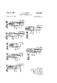
- FIGURES 1 and 1a when combined are an e'levational view in section of a bottle capper incorporating my invention.
- FIG. 2 is a fragmentary enlargement in section illustrating the torque limiting clutch and clutch control.
- FIG. 3 i aview taken along the line 33 of FIG. 2;
- FIG. 4 is a view taken along the line 4-4 of FIG. 2;
- FIG. 5 is a fragmentary view taken along the line 5-5 of FIG; 2;
- FIG. 6 is a sectional view similar to FIG. 3 but showing the clutch control and clutch parts in a different position relative to each other from that of FIG. 3;
- FIG. 7 is a fragmentary enlarged elevational view of part of the clutch and clutch control of FIG. -la during transmission [of torque between the constant speed drive and work;
- FIG. 8 is a fragmentary enlarged elevationalview with 3,10%366 Patented Aug. 13, 1963
- the device comprises essentially a constant speed drive spindle 12 journaled in a supporting structure 13 and supporting at the lower end thereof a collet '14 for engaging the cap 10.
- the spindle 12 is rotated through a clutch 15 by means of a constant speed drive 16, the clutch 15 being controlled by a clutch control 17.
- Spindle 12 includes a notary drive “sleeve 201and an inner shaft 21 freely rotatable and reciprocably rotated therein.
- Drive sleeve 20 is moved axially and relative to supporting structure 13 by means ozf'a supporting cam- I ming device 29a the details of which are not described herein because oamming devices for this purpose are commonly used in the industry and because the exact style and design of camming device used is incidental to the operation of the present invention so long as it performs the function of moving drive sleeve 20 axially thereof and relative to supporting structure 13.
- Inner shaft 21 moved axially and relative to supporting structure 13 by means of a supporting camming device 21a the details of which are not described herein because carnming devices for this purpose are commonly used in the industry and because the exact style and design of oaniming device used is incidental to the operation of the present invention so long as it performs the function of moving inner shaft 21 axially thereof and rela tive to supporting structure v13.
- camrning device 21a moves inner shaft 2 1 axially relative to drive sleeve 20.
- FIG. 9 is a sectional view taken along the line 9 -9 of FIG. 8;
- FIG. 10 is an elevational view partly in section illustrating resetting of the clutch and clutch control after the cap has been screwed on the bottle;
- FIG. 11 is a schematic diagram of a control speed drive driving work through a clutch control by a clutch control.
- FIGURES 12 to 18 inclusive illustrate the sequence of operations performed by the machine of FIGURES 1 and 10 wherein in FIG. 12 the collar and cap are positioned so that the collar may be lowered over the cap becomes apparent when it is recognized that the lower ends or inner shaft 21 and drive sleeve 20 support the inner and outer fingers 14a and 14b respectively of collet 14 which grips cap 10'.
- Ool'le-t 14 is a standard oollet in which relative movement between its inner fingers 14a and outer fingers 147; in an axial direction causes a releasing and gripping of the inner fingers on the cap.
- Drive sleeve 20*. and inner shaft 21 are operatively connected through clutch control 17' and clutch 15 in series through drive 16 as schematically illustrated in FIG. 11 and-fully illustrated in the detailed illustrations, FIGURES 1-10 inclusive.
- the clutch :15 in this instance ' is a standard roller bearing type clutch commonly used as a single revolution clutch which automatically disengages the driving power from the machine.
- this clutch comprises a drive sleeve 25 and a concentric inner driven sleeve 26 separated by a cage 27 supporting rollers 28.
- Drive sleeve 25 is directly connected to drive 16 for continuous constant speed rotation throughoutthe operation of the machine.
- Inner drive sleeve 26 is operatively associated With clutch control 17 to transmit torque received by it from drive sleeve 25 by means of cage 27 and supported rollers 28 to clutch control 17.
- the inner surface of drive sleeve 25 is cylindrical whereas the outer surface of driven sleeve 26 is provided with flats 30 one for each ofthe rollers 28.-
- the cage 27 holds these rollers in alignment.
- Extending from cage 27 in a direction towards clutch control 17 is a trip pin 31 which is engaged by an element of clutch control 17 to partially rotate cage 27 relative to drive sleeve 26 to move rollers 28 from their driving or wedged position between sleeve 26 and flats Bil-to discontinue transmittal of torque from drive sleeve 25 to inner drive sleeve 26.
- Clutch control 17 comprises essentially a pair of face plates 32 and 33 and a plurality of balls 34.
- Face plate 32 is secured to inner drive shaft 26 for movement there.- with and serves as the rotator for transmitting torque through balls 34 to face plate 33.
- F ace plate 33 is secured to spindle 12 to drive spindle 12 when it is driven through I balls 34 by face plate 32. Like all conmion ball and will permit separation of the plates bythe balls 34 when,
- 1 Clutch control 17 is completed by. providing face plate33 with a trouble pin 1 Iso aligned as to stop trip pin 31 when balls 34 are out .of sockets 32a,as shown in FIG. 6.
- Plate 32 has a notch .37 in the periphery thereof through which trouble pin 36 extends to contact pin 31.
- clutchcontrol'17 in a common housing 40 journaled in ,supporting structure 13 for rotation relative thereto and forfrotation with drive'16, clutch v15, clutch control 17 :and spindle '12. Housing 40 does not move axiallyrelative to supporting structure 13..
- spindle 12, clutch 15, and control clutch 17 move axially of housing 40 when camming device 20a and 21a move drive sleeve 20 and inner shaft'21' in axial directions relative to. each other and to support structure 13. This feature is used to reset clutch 15 and control clutch 17 after clutch 15 has beengdiseng'aged by control clutch 17 ina manner hereafter to'be'described.
- the structure which provides this feature includes radially extending reset pins 32p on face plate 32 and reset .pins 33p on face plate 33 pins 32p and 33p extend outwardly through tapered slot 41 which is wider. Tapered slot 41 is tapered in a direction such that reset pin 33p is permitted to have more reset pin 32p.
- v 'The'next step in the cycle is effectedcams 20 and 21b causing -sirnultaneous':jdownward axialimovement' of I
- the device is complete'dby enclosing clutch 15 and respectively, and a tapered slot 41 in housing 40. "Reset V I rotation relative to housing 4! ⁇ than face plate 32, and its 7 from rotating by the tightening of cap 19 on bottle 11.
- face plate 32' continues to rotate unt-il trip pin 31 on cage 27 abuts on trouble pin 36 on the stopped plate.
- the cage is thus stopped so that rollers 28 in the cage are backed away from their Wedging engagement between cylindrical surface 29' and flats '39 and driving engagement between dn've sleeve 25 and flats 39 on the sleeve26pisibrok-en and rotation of face plate 32'relative to plate 33'and cap 10 is also stopped.
- clutch control 17 has controlled clutch 15 by causing clutch 15 to become disengaged-so that it does'nottransmit torque from drive 16 to spindle 12, when a predetermined torque is applied to cap it
- clutch control 17, face plate 32 and face plate 33 are disengaged from driving positions are illustrated in FIGURES '6, 8; and 9.-. l
- cam 21a cause collet 14 to be lowered simultaneously 15 will stay disengaged until control clutch 17 is reset by the upward axial motion of the spindle assembly 12, cl'utch'15, constant speed drive 15 etc- During this upward movemennreset pinf33p inplate33 contacts cam face 41 in sleeve 41 and rotates plate 33 back relative to plate 32 ;until 'balls'34 are urged'by spring 35 into socket-s 32a This-movement also separates trouble pin 36 from trip pin '31 allowing-spring 45 to rotatecage 27 carrying rollers 28 into the driving position illustrated inEIG.
- a device for applying and tightening screw caps on containers comprising rotatable cap gripping means, driving means for rotating said gripping means, clutch means interposed between said gripping means and said driving means for disconnecting said driving and gripping means, said clutch means including a drive clutch having a trip pin extending axially from a drive element thereof, a control clutch driven by said drive clutch and having a second pin extending axially from a control element thereof and disposed in the path of said trip pin, said control clutch being adapted to slip when said cap gripping means is subjected to a predetermined torque whereupon said control element is stopped and said second pin thereon stops said trip pin and its drive element to disconnect said driving means from said gripping means, and means for resetting said control element whereby said pins are again separated and said driving and gripping means are reconnected so that said drive means, operating through said clutch means, again rotates said cap gripping means.
- said drive element is a roller bearing cage disposed intermediate input and output members of said drive clutch and said relative movement of said cage by the engagement of said pins removes the rollers in said cage from their wedged and driving engagement between said input and output members.
- control element is the output member of said control clutch, said control output member being stopped immediately under said predetermined torque so that said trip pin collides wardly relative to the input and output members of the drive clutch.
- a device for applying and tightening screw caps on containers comprising rotatable and vertically reciprocable cap gripping means, driving means for rotating said gripping means, clutch means interposed between said gripping means and said driving means for disconnecting said driving and gripping means when the latter is subjected to a predetermined torque, said clutch means including a drive clutch, a control clutch having a control element, and trip means intermediate said clutches and operable by said control element to disconnect said drive element when said control clutch is subjected to said predetermined torque, operating means for raising and lowering said gripping means and for moving said gripping means into gripping engagement against a said cap while applying the cap to a container, and to release said cap when said drive clutch is disconnected and rotation of said gripping means is thus stopped while the gripping means is in its lower position, and means for resetting said control element and trip means while said gripping means is raised by said operating means to its upper position, whereby said drive clutch is reconnected so that said cap gripping means is again rotated by said driving means.
- said cap gripping means is a collet having inner fingers biased to release positions disposed radially outwardly from their gripping positions, and an outer member for moving said fingers radially inwardly to their cap gripping positions when said outer member is moved axially relative with said stopped second pin on the control output memher whereby said trip pin and said cage are moved backto said fingers by said operating means.
Landscapes
- Engineering & Computer Science (AREA)
- Mechanical Engineering (AREA)
- Sealing Of Jars (AREA)
Description
Aug. 13, 1963 J. HJGORDON 3,100,366
SCREW CAP ASSEMBLING HEAD Filed June 16, 1961 5 Sheets-Sheet 1 f0 fry. 1a
INVENTOR. JIMEZS HENRY GOPOON 14 T TUBA/[Y5 Aug. 13, 1963 J. H. GORDON, 3,100,366
SCREW CAP ASSEMBLING HEAD Filed June 16, 1961 I I 5 Sheets-Sheet 2 Hula. i 4fl l /7 i g MZ I IIIVENTOR.
JAMES HL-WEY qoeaolv J. H. GORDON SCREW CAP ASSEMBLING HEAD Aug. 13, 1963 5 Sheets-Sheet 3 Filed June 16, 1961 .N 5 mm MW W M m IV T E? A M H a y .MB
Aug. 13, 1963 .1. H. GORDON 3,100,366
SCREW CAP ASSEMBLING HEAD Filed June 16 1961 5 Sheets-Sheet 4 3% liq/.11
CONSTANT /i* 5 /fcLuraH I 7 CLUTCH i! CU/VTROL INVENTOR. m MES f/E/VE Y 60/900 Aug. 13, 1963 J. H. GORDON SCREW CAP ASSEMBLING HEAD 5 Sheets-Sheet 5 Filed June 16, 1961 MN NN 5 mm N M m E0 0 V6 W7 myw r E m 5 5 my J B United States Patent Filed June 16, 1961, Ser. No. 117,729 Claims. c1. 53 317 This invention relates to an apparatus for applying screw caps to threaded bottles and the like.
One of the objects of the present invention is to provide structure which will screw a cap on a bottle until a predetermined torque limit is reached during the assembly and then release itself so as to avoid breaking the cap or the bottle.
A further :object of the invention is to provide a torque limiting clutch arrangement on a spindle capable of disengaging when the ctorque reaches a predetermined limit.
A further object of the present invention is to provide a clutch between a constant speed drive and the work and a clutch control in series between the clutch and the work to control engagement of the clutcb, the clutch control being responsive to the torque transmitted through the clutch to the work.
Numerous other objects and advantages of the invention will be apparent as it is better understood from the following description, which, taken in connection with the accompanying drawings, discloses a preferred embodiment thereof.
FIGURES 1 and 1a when combined are an e'levational view in section of a bottle capper incorporating my invention.
FIG. 2 is a fragmentary enlargement in section illustrating the torque limiting clutch and clutch control.
FIG. 3 i aview taken along the line 33 of FIG. 2;
FIG. 4 is a view taken along the line 4-4 of FIG. 2;
FIG. 5 is a fragmentary view taken along the line 5-5 of FIG; 2;
FIG. 6 is a sectional view similar to FIG. 3 but showing the clutch control and clutch parts in a different position relative to each other from that of FIG. 3;
FIG. 7 is a fragmentary enlarged elevational view of part of the clutch and clutch control of FIG. -la during transmission [of torque between the constant speed drive and work;
FIG. 8 is a fragmentary enlarged elevationalview with 3,10%366 Patented Aug. 13, 1963 As previously set torth the purpose of the present machine is to screw a cap 10 on a bottle 11 without breaking the cap or. the bottle. The device comprises essentially a constant speed drive spindle 12 journaled in a supporting structure 13 and supporting at the lower end thereof a collet '14 for engaging the cap 10. The spindle 12 is rotated through a clutch 15 by means of a constant speed drive 16, the clutch 15 being controlled by a clutch control 17. v
Spindle 12 includes a notary drive "sleeve 201and an inner shaft 21 freely rotatable and reciprocably rotated therein. Drive sleeve 20 is moved axially and relative to supporting structure 13 by means ozf'a supporting cam- I ming device 29a the details of which are not described herein because oamming devices for this purpose are commonly used in the industry and because the exact style and design of camming device used is incidental to the operation of the present invention so long as it performs the function of moving drive sleeve 20 axially thereof and relative to supporting structure 13. Inner shaft 21 moved axially and relative to supporting structure 13 by means of a supporting camming device 21a the details of which are not described herein because carnming devices for this purpose are commonly used in the industry and because the exact style and design of oaniming device used is incidental to the operation of the present invention so long as it performs the function of moving inner shaft 21 axially thereof and rela tive to supporting structure v13. In addition, camrning device 21a moves inner shaft 2 1 axially relative to drive sleeve 20. The reason for the axial movements of drive sleeve 20 and inner shaft 21 by the cams 20a and 21a parts broken away and other parts in cross section illustrating the position of the clutch control immediately after a torque limit has been reached and transmission of power between the constant speed drive and the work has ceased;
FIG. 9 is a sectional view taken along the line 9 -9 of FIG. 8;
FIG. 10 is an elevational view partly in section illustrating resetting of the clutch and clutch control after the cap has been screwed on the bottle;
FIG. 11 is a schematic diagram of a control speed drive driving work through a clutch control by a clutch control.
' FIGURES 12 to 18 inclusive illustrate the sequence of operations performed by the machine of FIGURES 1 and 10 wherein in FIG. 12 the collar and cap are positioned so that the collar may be lowered over the cap becomes apparent when it is recognized that the lower ends or inner shaft 21 and drive sleeve 20 support the inner and outer fingers 14a and 14b respectively of collet 14 which grips cap 10'. Ool'le-t 14 is a standard oollet in which relative movement between its inner fingers 14a and outer fingers 147; in an axial direction causes a releasing and gripping of the inner fingers on the cap.
f-by excessive torque, they/are forcedout of the sockets 32a-onto the face of plate 32. 1 Clutch control 17 is completed by. providing face plate33 with a trouble pin 1 Iso aligned as to stop trip pin 31 when balls 34 are out .of sockets 32a,as shown in FIG. 6. Plate 32 has a notch .37 in the periphery thereof through which trouble pin 36 extends to contact pin 31.
clutchcontrol'17 in a common housing 40 journaled in ,supporting structure 13 for rotation relative thereto and forfrotation with drive'16, clutch v15, clutch control 17 :and spindle '12. Housing 40 does not move axiallyrelative to supporting structure 13.. Thus, spindle 12, clutch 15, and control clutch 17 move axially of housing 40 when camming device 20a and 21a move drive sleeve 20 and inner shaft'21' in axial directions relative to. each other and to support structure 13. This feature is used to reset clutch 15 and control clutch 17 after clutch 15 has beengdiseng'aged by control clutch 17 ina manner hereafter to'be'described. However; the structure which provides this feature includes radially extending reset pins 32p on face plate 32 and reset .pins 33p on face plate 33 pins 32p and 33p extend outwardly through tapered slot 41 which is wider. Tapered slot 41 is tapered in a direction such that reset pin 33p is permitted to have more reset pin 32p.-
7 1 Operation I v v A complete cycle of operation willlbe described in connection with FIGURES 12 to 18 inclusive with reference'to-FIGURES 1 and *la and the other figures in the drawing; At the start of the cycle clutch '15, and clutch control 17' are in driving position 'as illustrated'in FIG- URES la, 2, 3, 4, 7, and 12. Inner and outer fingers 14a and 1415 are positioned relative to each other as illus tratedin FIGURE 12. Throughout the cycle of' operation drive16 continues to rotate clutch 15 ata constant speed;
v 'The'next step in the cycle is effectedcams 20 and 21b causing -sirnultaneous':jdownward axialimovement' of I The device: is complete'dby enclosing clutch 15 and respectively, and a tapered slot 41 in housing 40. "Reset V I rotation relative to housing 4!} than face plate 32, and its 7 from rotating by the tightening of cap 19 on bottle 11.
Following this termination of torque transmission be tween face plates 32 and 33, face plate 32' continues to rotate unt-il trip pin 31 on cage 27 abuts on trouble pin 36 on the stopped plate. The cage is thus stopped so that rollers 28 in the cage are backed away from their Wedging engagement between cylindrical surface 29' and flats '39 and driving engagement between dn've sleeve 25 and flats 39 on the sleeve26pisibrok-en and rotation of face plate 32'relative to plate 33'and cap 10 is also stopped. Thus it is' apparent that clutch control 17 has controlled clutch 15 by causing clutch 15 to become disengaged-so that it does'nottransmit torque from drive 16 to spindle 12, when a predetermined torque is applied to cap it The positions of the parts at this time and while the clutch 15, clutch control 17, face plate 32 and face plate 33 are disengaged from driving positions are illustrated in FIGURES '6, 8; and 9.-. l
' "While thus disengaged inner drive sleeve 26 is not being driven, rotated or receiving torque from drive sleeve 25 so as to permitrelative movement between drive sleeve '26 and cage 27 in a direction which will move rollers 28 to a wedging position between flats 3t! and cylindrical surface 23 for transmission of torque from drive sleeve 25 to drive sleeve 26. A spring 4-5 (FIG- URES 2, 4, and 5) is interconnected between drive sleeve '26 and cage 27 to serve as a bias to restore rollers 38 to a'wedging or driving position between sleeve 25 and flats 300m shaft'26- when. the collet 14 is released from the tightened cap 10 and clutch control 17 is reset.
After-clutch control 17 has disengaged clutch 15, by
3 the'burnping of trip pin 31 against trouble pin 36, clutch drivesleeve'20iand inner shaft 21 to, place collet 14 over I andarounda cap 10 as illustrated in FIG. l3-and then 'causing'only'drive sleeve '20 and its collet sleeve 14b to move downwardly relative tofingers 14a, so that fingers 14a are'moved inwardly togrip the cap 1% as illustrated in FIGUR-ES,1,'1a, and 14. Inthis position drive sleeve to spin with spindle 1-2. 7 p 7 The next step in the cycle is effected through cams 20a and 21a to raise drive'sleeve 2t} and cam 21a thereby fingers 1-4a'and 14b which now grip cap 10, cause the cap lifting collet 14 and cap 10 gripped thereby as illustrated in FIG. 1'5 while drive 16"conti'nues to rotate spindle 12 and cap. 10v therewith so that a bottle 11 may be placed under the rotating cap 10v as illustrated in FIG. 15. After a bottle has been placed under collet 14, cam 2th: and
cam 21a cause collet 14 to be lowered simultaneously 15 will stay disengaged until control clutch 17 is reset by the upward axial motion of the spindle assembly 12, cl'utch'15, constant speed drive 15 etc- During this upward movemennreset pinf33p inplate33 contacts cam face 41 in sleeve 41 and rotates plate 33 back relative to plate 32 ;until 'balls'34 are urged'by spring 35 into socket-s 32a This-movement also separates trouble pin 36 from trip pin '31 allowing-spring 45 to rotatecage 27 carrying rollers 28 into the driving position illustrated inEIG. This immediately establishes, transmission of itorq ue frorn drive sleeve 25, which is continually'rotated 1 "by drive'l, through rollers 28 andto drive sleeve 26 and through torque control clutchl'i to spindle 12. In
l tl;iis rotation the path-of drivingtorqueis from drive 16 through drive sleeve 25 thence through rollers 28, cage 27, drive ,sleeve'26 through torque control clutch 17 and I thus into spindle 12.
I claim:
1. A device for applying and tightening screw caps on containers, said device comprising rotatable cap gripping means, driving means for rotating said gripping means, clutch means interposed between said gripping means and said driving means for disconnecting said driving and gripping means, said clutch means including a drive clutch having a trip pin extending axially from a drive element thereof, a control clutch driven by said drive clutch and having a second pin extending axially from a control element thereof and disposed in the path of said trip pin, said control clutch being adapted to slip when said cap gripping means is subjected to a predetermined torque whereupon said control element is stopped and said second pin thereon stops said trip pin and its drive element to disconnect said driving means from said gripping means, and means for resetting said control element whereby said pins are again separated and said driving and gripping means are reconnected so that said drive means, operating through said clutch means, again rotates said cap gripping means.
2. The device set forth in claim 1 wherein said drive element is a roller bearing cage disposed intermediate input and output members of said drive clutch and said relative movement of said cage by the engagement of said pins removes the rollers in said cage from their wedged and driving engagement between said input and output members.
3. The device set forth in claim 2 wherein said control element is the output member of said control clutch, said control output member being stopped immediately under said predetermined torque so that said trip pin collides wardly relative to the input and output members of the drive clutch.
4. A device for applying and tightening screw caps on containers, said device comprising rotatable and vertically reciprocable cap gripping means, driving means for rotating said gripping means, clutch means interposed between said gripping means and said driving means for disconnecting said driving and gripping means when the latter is subjected to a predetermined torque, said clutch means including a drive clutch, a control clutch having a control element, and trip means intermediate said clutches and operable by said control element to disconnect said drive element when said control clutch is subjected to said predetermined torque, operating means for raising and lowering said gripping means and for moving said gripping means into gripping engagement against a said cap while applying the cap to a container, and to release said cap when said drive clutch is disconnected and rotation of said gripping means is thus stopped while the gripping means is in its lower position, and means for resetting said control element and trip means while said gripping means is raised by said operating means to its upper position, whereby said drive clutch is reconnected so that said cap gripping means is again rotated by said driving means.
5. The device set forth in claim 7 wherein said cap gripping means is a collet having inner fingers biased to release positions disposed radially outwardly from their gripping positions, and an outer member for moving said fingers radially inwardly to their cap gripping positions when said outer member is moved axially relative with said stopped second pin on the control output memher whereby said trip pin and said cage are moved backto said fingers by said operating means.
References Cited in the file of this patent UNITED STATES PATENTS Great Britain Nov. 13,
Claims (1)
1. A DEVICE FOR APPLYING AND TIGHTENING SCREW CAPS ON CONTAINERS, SAID DEVICE COMPRISING ROTATABLE CAP GRIPPING MEANS, DRIVING MEANS FOR ROTATING SAID GRIPPING MEANS, CLUTCH MEANS INTERPOSED BETWEEN SAID GRIPPING MEANS AND SAID DRIVING MEANS FOR DISCONNECTING SAID DRIVING AND GRIPPING MEANS, SAID CLUTCH MEANS INCLUDING A DRIVE CLUTCH HAVING A TRIP PIN EXTENDING AXIALLY FROM A DRIVE ELEMENT THEREOF, A CONTROL CLUTCH DRIVEN BY SAID DRIVE CLUTCH AND HAVING A SECOND PIN EXTENDING AXIALLY FROM A CONTROL ELEMENT THEREOF AND DISPOSED IN THE PATH OF SAID TRIP PIN, SAID CONTROL CLUTCH BEING ADAPTED TO SLIP WHEN SAID CAP GRIPPING MEANS IS SUBJECTED TO A PREDETERMINED TORQUE WHEREUPON SAID CONTROL ELEMENT IS STOPPED AND SAID SECOND PIN THEREON STOPS SAID TRIP PIN AND ITS DRIVE ELEMENT TO DISCONNECT SAID DRIVING MEANS FROM SAID GRIPPING MEANS, AND MEANS FOR RESETTING SAID CONTROL ELEMENT WHEREBY SAID PINS ARE AGAIN SEPARATED AND SAID DRIVING AND GRIPPING MEANS ARE RECONNECTED SO THAT SAID DRIVE MEANS, OPERATING THROUGH SAID CLUTCH MEANS, AGAIN ROTATES SAID CAP GRIPPING MEANS.
Priority Applications (1)
| Application Number | Priority Date | Filing Date | Title |
|---|---|---|---|
| US117729A US3100366A (en) | 1961-06-16 | 1961-06-16 | Screw cap assembling head |
Applications Claiming Priority (1)
| Application Number | Priority Date | Filing Date | Title |
|---|---|---|---|
| US117729A US3100366A (en) | 1961-06-16 | 1961-06-16 | Screw cap assembling head |
Publications (1)
| Publication Number | Publication Date |
|---|---|
| US3100366A true US3100366A (en) | 1963-08-13 |
Family
ID=22374528
Family Applications (1)
| Application Number | Title | Priority Date | Filing Date |
|---|---|---|---|
| US117729A Expired - Lifetime US3100366A (en) | 1961-06-16 | 1961-06-16 | Screw cap assembling head |
Country Status (1)
| Country | Link |
|---|---|
| US (1) | US3100366A (en) |
Cited By (5)
| Publication number | Priority date | Publication date | Assignee | Title |
|---|---|---|---|---|
| US3253388A (en) * | 1963-01-25 | 1966-05-31 | Continental Can Co | Rotary jar capping machine |
| US3491516A (en) * | 1967-10-25 | 1970-01-27 | Pneumatic Scale Corp | Closure applying apparatus |
| US3906706A (en) * | 1973-12-13 | 1975-09-23 | Dairy Cap Corp | Cap-tightener |
| US4232499A (en) * | 1978-08-01 | 1980-11-11 | John H. Holstein | Capper chuck |
| US20250376365A1 (en) * | 2024-06-05 | 2025-12-11 | Krones Ag | Apparatus for closing a container |
Citations (4)
| Publication number | Priority date | Publication date | Assignee | Title |
|---|---|---|---|---|
| US2610779A (en) * | 1946-10-11 | 1952-09-16 | Anchor Hocking Glass Corp | Hermetic sealing machine with vacuum control means |
| GB786099A (en) * | 1955-06-03 | 1957-11-13 | Crown Cork Company Ltd | Improvements in or relating to devices for tightening screw closures in or around the mouths of bottles or like containers |
| US2966973A (en) * | 1954-04-01 | 1961-01-03 | Henry L Hayes | Torque clutch |
| US2973848A (en) * | 1959-03-02 | 1961-03-07 | Dixon Automatic Tool | Torque responsive clutch |
-
1961
- 1961-06-16 US US117729A patent/US3100366A/en not_active Expired - Lifetime
Patent Citations (4)
| Publication number | Priority date | Publication date | Assignee | Title |
|---|---|---|---|---|
| US2610779A (en) * | 1946-10-11 | 1952-09-16 | Anchor Hocking Glass Corp | Hermetic sealing machine with vacuum control means |
| US2966973A (en) * | 1954-04-01 | 1961-01-03 | Henry L Hayes | Torque clutch |
| GB786099A (en) * | 1955-06-03 | 1957-11-13 | Crown Cork Company Ltd | Improvements in or relating to devices for tightening screw closures in or around the mouths of bottles or like containers |
| US2973848A (en) * | 1959-03-02 | 1961-03-07 | Dixon Automatic Tool | Torque responsive clutch |
Cited By (5)
| Publication number | Priority date | Publication date | Assignee | Title |
|---|---|---|---|---|
| US3253388A (en) * | 1963-01-25 | 1966-05-31 | Continental Can Co | Rotary jar capping machine |
| US3491516A (en) * | 1967-10-25 | 1970-01-27 | Pneumatic Scale Corp | Closure applying apparatus |
| US3906706A (en) * | 1973-12-13 | 1975-09-23 | Dairy Cap Corp | Cap-tightener |
| US4232499A (en) * | 1978-08-01 | 1980-11-11 | John H. Holstein | Capper chuck |
| US20250376365A1 (en) * | 2024-06-05 | 2025-12-11 | Krones Ag | Apparatus for closing a container |
Similar Documents
| Publication | Publication Date | Title |
|---|---|---|
| US3100366A (en) | Screw cap assembling head | |
| US3034623A (en) | Cam clutch device | |
| US4460077A (en) | Overload clutch assembly | |
| US3095955A (en) | Overload clutch or torque limiting device | |
| CN105485197B (en) | Torque limiter with flexible sheet shaft coupling | |
| US1927509A (en) | Safety clutch mechanism | |
| US2140255A (en) | Automatic clutch coupling | |
| CN205446463U (en) | Novel clutch device | |
| EP0013913A1 (en) | Anti-reversal device | |
| US2728428A (en) | Automatic transmission and brake for clothes washers and the like | |
| US2366841A (en) | Coupling | |
| US2148481A (en) | Press clutch | |
| WO2020237589A1 (en) | Clutch coupling | |
| US2364980A (en) | Safety device | |
| US4946016A (en) | Device for controlling positioned stopping of a packaging unit | |
| US3110192A (en) | Transmission | |
| US2299621A (en) | Clutch operating mechanism | |
| US1713909A (en) | Clutch | |
| US1669585A (en) | Driving mechanism for the spindles of spinning and like machines | |
| US2433553A (en) | Speed responsive controlled oneway engaging clutch | |
| CN103174773A (en) | Automatic reset safety clutch device used for filling machine | |
| USRE15550E (en) | Driving mechanism for airships | |
| US1775741A (en) | Automatic shaft coupling | |
| US2010925A (en) | Automatic power coupling and cut-off | |
| US3104855A (en) | barish |