US314391A - Machine for shaving curved stereotype-plates - Google Patents
Machine for shaving curved stereotype-plates Download PDFInfo
- Publication number
- US314391A US314391A US314391DA US314391A US 314391 A US314391 A US 314391A US 314391D A US314391D A US 314391DA US 314391 A US314391 A US 314391A
- Authority
- US
- United States
- Prior art keywords
- plates
- machine
- shaving
- type
- plate
- Prior art date
- Legal status (The legal status is an assumption and is not a legal conclusion. Google has not performed a legal analysis and makes no representation as to the accuracy of the status listed.)
- Expired - Lifetime
Links
- 230000037431 insertion Effects 0.000 description 5
- 238000003780 insertion Methods 0.000 description 5
- 230000001012 protector Effects 0.000 description 4
- 208000027418 Wounds and injury Diseases 0.000 description 3
- 238000010276 construction Methods 0.000 description 3
- 230000006378 damage Effects 0.000 description 3
- 208000014674 injury Diseases 0.000 description 3
- 239000000463 material Substances 0.000 description 3
- 230000001276 controlling effect Effects 0.000 description 2
- 230000000694 effects Effects 0.000 description 2
- 239000004744 fabric Substances 0.000 description 2
- 229910001369 Brass Inorganic materials 0.000 description 1
- ATJFFYVFTNAWJD-UHFFFAOYSA-N Tin Chemical compound [Sn] ATJFFYVFTNAWJD-UHFFFAOYSA-N 0.000 description 1
- 239000010951 brass Substances 0.000 description 1
- 230000000266 injurious effect Effects 0.000 description 1
- 230000001105 regulatory effect Effects 0.000 description 1
- 238000010008 shearing Methods 0.000 description 1
Images
Classifications
-
- B—PERFORMING OPERATIONS; TRANSPORTING
- B23—MACHINE TOOLS; METAL-WORKING NOT OTHERWISE PROVIDED FOR
- B23D—PLANING; SLOTTING; SHEARING; BROACHING; SAWING; FILING; SCRAPING; LIKE OPERATIONS FOR WORKING METAL BY REMOVING MATERIAL, NOT OTHERWISE PROVIDED FOR
- B23D3/00—Planing or slotting machines cutting by relative movement of the tool and workpiece in a vertical or inclined straight line
- B23D3/04—Planing or slotting machines cutting by relative movement of the tool and workpiece in a vertical or inclined straight line in which the tool or workpiece is fed otherwise than in a straight line
-
- Y—GENERAL TAGGING OF NEW TECHNOLOGICAL DEVELOPMENTS; GENERAL TAGGING OF CROSS-SECTIONAL TECHNOLOGIES SPANNING OVER SEVERAL SECTIONS OF THE IPC; TECHNICAL SUBJECTS COVERED BY FORMER USPC CROSS-REFERENCE ART COLLECTIONS [XRACs] AND DIGESTS
- Y10—TECHNICAL SUBJECTS COVERED BY FORMER USPC
- Y10T—TECHNICAL SUBJECTS COVERED BY FORMER US CLASSIFICATION
- Y10T409/00—Gear cutting, milling, or planing
- Y10T409/50—Planing
- Y10T409/50328—Means for shaving by blade spanning work surface
- Y10T409/503444—Concave work surface [e.g., bearing, stereotype printing plate, etc,]
Definitions
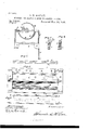
- Figure l is a cross-section on linear a; of Fig.
- the feeder F can be made of the material 2; Fig. 2, a top or plan view with the plate used for tympansheets. Its opposite or tail and breaker removed; Fig. 3, a plan view of endis provided with the rod 0, which, as" the feeder and breaker; Fig. 4, a side view of shown, is made to project so that it can read 65 the clamp for the feeder and breaker; Fig. 5, ily be grasped. a cross-section on line y of Fig. 3 enlarged; In use the feeder and typeprotector is laid Fig. 6, a side view of another form of clamp.
- A indicates the frame of the machine; B, the concave for receiving and holding the stereotype-plates; C, the shaving blade; D, the stop -plate; E, curved stereotype-plate; F, the feeder and type-protector; a, clamping head or bar attached to the front or leading edge of the breaker; b, a groove in the head a for preventing the head from inj uring any projecting type or figure faces; 0, cross-rod for the tail end of the breaker; d, guides or stops for holding the clamp a in position; e, projecting ends of the clamp a.
- the frame A, concave B, and cutter or shave C are made in the usual manner, and fitted to receive stereotype-segments of the size and curve suited to the cylinder to which the finished stereotype-plates are to be applied.
- the concave B is provided with the stop-plate D, which prevents the moving of the plate within the concave when the shaveis applied, and at the ends of this plate D the stops or guides d are applied, beneath which the ends 6 of the clamp a pass. These stops are bent down, as shown in Fig. 1, and in this form they prevent the clamp a from getting out of position, or soas to come in contact with the rotary shave C.
- the clamp or head a is preferably made of two bars, as shown, as by this construction insufficient.
- a counter-weight or treadle can be used, if desired, for controlling the insertion and release of the plates; but ordinarily the movement of the feeder will be sufficiently controlled by the operator without other de vices.
- the plate is easily fed into position for shearing, and as its insertion carries the head (1 along the protector is. evenly and smoothly So fed in between the concave and the type-faces, so that no injury whatever occurs to the faces of the type, and the movement of the stereotype-plate is easily controlled and regulated.
- the heavy pressure of the knife in shaving the plate has heretofore had the effect ofcrushing any projecting letters or parts of cuts, but by the use of this protector such slight proj ections become embedded therein and remain uninjured by the pressure of the shaving-knife.
- the application of the shaving-knife to hot plates also has a tendency to cause them to fit the concave so closely as tofrequently adhere or become set in position, thus requiring the application of chisels or other tools to loosen them; but by using the feeder and protector F the plates do not become set, and by taking hold of the rod 0 they can, when finished, be as readily withdrawn as they are inserted.
- a clamping form of the head a which enables the feeder to be readily inserted and firmly held, is the most desirable construction for this purpose; but I do not limit myself to one made of two pieces, as by providing a proper recess beneath the stop-plate D different constructions may be used, and the clamp can also be made of a single bar.
- One form of making the clamp in a slightly-different manner is shown in Fig. 6, in which the clamp is made in two pieces'with their adjoining faces running diagonal to form the opening for the end of the feeder, which gives a wider clampingsurface.
- the feeder and type-protector can be made of cloth or other fabric, strong paper, or a softmetal sheet of tin or other material, the only requisite being that the material shall be of sufficiently yielding nature to allow the face of the type to embed therein without injurious 5 effects, and of sufficient strength to withstand the strain of inserting the plates.
- the type-protecting feeder F interposed between the concave bed and the type-face of the inserted plate, substantially as described.
- clamping bar or head 0 having the groove 12, in combination with the feeding typeprotector F, for preserving the form of the type-faces, substantially as specified.
Landscapes
- Engineering & Computer Science (AREA)
- Mechanical Engineering (AREA)
- Knives (AREA)
Description
(No Model.)
A. D. MGLEAN.
MACHINE FOR SHAVING GURVED STEREOTYPE PLATES.
N0.,31 ,391' Patented Mar. 24, 1885. JLugfifl I m$$r jaavejnf o r:
UNTTan STATES PATENT c m.
ALEXANDER D. MCLEAN, OF CHICAGO, ILLINOIS.
MACHINE FOR SHAVING CURVED STEREOTYPE-PLATES.
SPECIFICATION forming part of LettersiPatent No. 31%,391, dated March 24, 1885.
Application filed April 3, 1884. (N model.)
To all whom it may concern.- the feeder and type protector F is firmly,
States, have inventedcertain new and useful type-plate this head or clamp is provided Improvementsin Machines forShaving Curved with the groove I), so that the plates may pass Stereotype-Plates, of which the following is a under the head or clamp and at the same time full description, reference beinghad to the be firmly held without injuring or marring 6o accompanying drawings, in which them. a
10 Figure l is a cross-section on linear a; of Fig. The feeder F can be made of the material 2; Fig. 2, a top or plan view with the plate used for tympansheets. Its opposite or tail and breaker removed; Fig. 3, a plan view of endis provided with the rod 0, which, as" the feeder and breaker; Fig. 4, a side view of shown, is made to project so that it can read 65 the clamp for the feeder and breaker; Fig. 5, ily be grasped. a cross-section on line y of Fig. 3 enlarged; In use the feeder and typeprotector is laid Fig. 6, a side view of another form of clamp. on the machine in about the position'shown The object of this improvement is to fain Fig. 1, when the leading edge ofthe stereocilitate the shaving of curved stereotypetype-plate is placed against the clamp to, and 70 plates in shaving machines, and have the actthe operator, by pressing his body against the performed without injury to the type or letfeeder, can control the insertion of the plate E Be it known that I, ALEXANDER D. MoLEAN, residing at Chicago, in the county of Cook and State of Illinois, and a citizen of the United ter faces, and also to permit of the easy insertion and removal of the stereotype-plates from the machine; and its nature consists in the improvements hereinafter claimed as new.
In the drawings, A indicates the frame of the machine; B, the concave for receiving and holding the stereotype-plates; C, the shaving blade; D, the stop -plate; E, curved stereotype-plate; F, the feeder and type-protector; a, clamping head or bar attached to the front or leading edge of the breaker; b, a groove in the head a for preventing the head from inj uring any projecting type or figure faces; 0, cross-rod for the tail end of the breaker; d, guides or stops for holding the clamp a in position; e, projecting ends of the clamp a.
The frame A, concave B, and cutter or shave C are made in the usual manner, and fitted to receive stereotype-segments of the size and curve suited to the cylinder to which the finished stereotype-plates are to be applied. The concave B is provided with the stop-plate D, which prevents the moving of the plate within the concave when the shaveis applied, and at the ends of this plate D the stops or guides d are applied, beneath which the ends 6 of the clamp a pass. These stops are bent down, as shown in Fig. 1, and in this form they prevent the clamp a from getting out of position, or soas to come in contact with the rotary shave C. The clamp or head a is preferably made of two bars, as shown, as by this construction insufficient.
evenly, and strongly attached thereto; and
in order to prevent injury to any projecting 5 letters or figures on the surface of the stereoat pleasure. A counter-weight or treadle can be used, if desired, for controlling the insertion and release of the plates; but ordinarily the movement of the feeder will be sufficiently controlled by the operator without other de vices. The plate is easily fed into position for shearing, and as its insertion carries the head (1 along the protector is. evenly and smoothly So fed in between the concave and the type-faces, so that no injury whatever occurs to the faces of the type, and the movement of the stereotype-plate is easily controlled and regulated.
By this arrangement the use of brass linings for the concave is avoided; also the insertion of paper, which has been found difficult and The feeder and type-protector adds to the utility of the machine in respect to inserting, controlling, and releasing the plates, and handling the plate with more case and certainty than has heretofore been done.
It will be understood that the plates are usually too hot to be handled by the naked hand when they are placed in the shavi ngmachines, 9 5
and for this reason, among others, their manipulation in inserting them in this class of machines has heretofore been difficult, and particularly so whenever a paper lining has been attempted to be used.
The heavy pressure of the knife in shaving the plate has heretofore had the effect ofcrushing any projecting letters or parts of cuts, but by the use of this protector such slight proj ections become embedded therein and remain uninjured by the pressure of the shaving-knife. The application of the shaving-knife to hot plates also has a tendency to cause them to fit the concave so closely as tofrequently adhere or become set in position, thus requiring the application of chisels or other tools to loosen them; but by using the feeder and protector F the plates do not become set, and by taking hold of the rod 0 they can, when finished, be as readily withdrawn as they are inserted. The use of my improvement greatly facilitates the shaving of these plates besides the protection it affords to the type-faces and the ease of inserting and retracting the plates. A clamping form of the head a, which enables the feeder to be readily inserted and firmly held, is the most desirable construction for this purpose; but I do not limit myself to one made of two pieces, as by providing a proper recess beneath the stop-plate D different constructions may be used, and the clamp can also be made of a single bar. One form of making the clamp in a slightly-different manner is shown in Fig. 6, in which the clamp is made in two pieces'with their adjoining faces running diagonal to form the opening for the end of the feeder, which gives a wider clampingsurface.
The feeder and type-protector can be made of cloth or other fabric, strong paper, or a softmetal sheet of tin or other material, the only requisite being that the material shall be of sufficiently yielding nature to allow the face of the type to embed therein without injurious 5 effects, and of sufficient strength to withstand the strain of inserting the plates.
What I claim as new, and desire to secure by Letters Patent, is
1. In a machine for shaving curved stereo- 4o type-plates, the type-protecting feeder F, interposed between the concave bed and the type-face of the inserted plate, substantially as described.
2. The combination of the head a, having 5 the grooves b and concaved bed 13, with the feeding and type-protecting sheet F and guides or holders 01, substantially as described.
3. The clamping bar or head 0, having the groove 12, in combination with the feeding typeprotector F, for preserving the form of the type-faces, substantially as specified.
4. The combination of the head a, feedingprotector F, and rod a, substantially as de scribed.
ALEXANDER D. MOLEAN.
Witnesses:
ALBERT H. ADAMS, O. W.-BOND.
Publications (1)
| Publication Number | Publication Date |
|---|---|
| US314391A true US314391A (en) | 1885-03-24 |
Family
ID=2383540
Family Applications (1)
| Application Number | Title | Priority Date | Filing Date |
|---|---|---|---|
| US314391D Expired - Lifetime US314391A (en) | Machine for shaving curved stereotype-plates |
Country Status (1)
| Country | Link |
|---|---|
| US (1) | US314391A (en) |
-
0
- US US314391D patent/US314391A/en not_active Expired - Lifetime
Similar Documents
| Publication | Publication Date | Title |
|---|---|---|
| US314391A (en) | Machine for shaving curved stereotype-plates | |
| US318556A (en) | Device for trimming wall-paper | |
| US179645A (en) | Improvement in machines for cutting leather | |
| DE2055035C3 (en) | Punching machine for sheet or foil-like material | |
| US969371A (en) | Cutting-stick for paper-cutting machines. | |
| US1034089A (en) | Line-casting machine. | |
| US996140A (en) | Cutting apparatus for paper-cutting machines. | |
| US1040262A (en) | Paper-cutting machine. | |
| US1758423A (en) | Veneer knife | |
| US1035200A (en) | Adjustable block for book-trimming machines. | |
| US71259A (en) | Josiah ye a gee | |
| US465435A (en) | Paper-cutting machine | |
| US958395A (en) | Cutting-stick for paper-cutting machines. | |
| US840553A (en) | Machine for cutting paper, cardboard, or other stock. | |
| US1126768A (en) | Stereotype-plate. | |
| EP1074357A3 (en) | Rotary cutter | |
| US746462A (en) | Toothpick-machine. | |
| US298667A (en) | Paper-perforating device | |
| US786633A (en) | Stencil-duplicating apparatus. | |
| US209526A (en) | Improvement in machines for marking plug-tobacco | |
| US773172A (en) | Machine-clamp. | |
| US381737A (en) | Method of renewing strainer-plates for paper-machines | |
| JPS6229204Y2 (en) | ||
| US645073A (en) | Quad-forming attachment for linotype-machines. | |
| US1858040A (en) | Packing stabber |