US3145263A - Black level stabilization circuit - Google Patents
Black level stabilization circuit Download PDFInfo
- Publication number
- US3145263A US3145263A US136607A US13660761A US3145263A US 3145263 A US3145263 A US 3145263A US 136607 A US136607 A US 136607A US 13660761 A US13660761 A US 13660761A US 3145263 A US3145263 A US 3145263A
- Authority
- US
- United States
- Prior art keywords
- waveform
- television
- gating
- circuit
- clamp
- Prior art date
- Legal status (The legal status is an assumption and is not a legal conclusion. Google has not performed a legal analysis and makes no representation as to the accuracy of the status listed.)
- Expired - Lifetime
Links
- 230000006641 stabilisation Effects 0.000 title description 3
- 238000011105 stabilization Methods 0.000 title description 3
- 230000008878 coupling Effects 0.000 claims description 10
- 238000010168 coupling process Methods 0.000 claims description 10
- 238000005859 coupling reaction Methods 0.000 claims description 10
- 239000002131 composite material Substances 0.000 claims description 6
- 241000220010 Rhode Species 0.000 description 1
- 239000004020 conductor Substances 0.000 description 1
- 238000010586 diagram Methods 0.000 description 1
- 230000004069 differentiation Effects 0.000 description 1
- 230000005021 gait Effects 0.000 description 1
- 230000004048 modification Effects 0.000 description 1
- 238000012986 modification Methods 0.000 description 1
- 238000005070 sampling Methods 0.000 description 1
- 238000007493 shaping process Methods 0.000 description 1
Images
Classifications
-
- H—ELECTRICITY
- H04—ELECTRIC COMMUNICATION TECHNIQUE
- H04N—PICTORIAL COMMUNICATION, e.g. TELEVISION
- H04N5/00—Details of television systems
- H04N5/44—Receiver circuitry for the reception of television signals according to analogue transmission standards
- H04N5/52—Automatic gain control
- H04N5/53—Keyed automatic gain control
Definitions
- the present invention relates to a circuit arrangement for obtaining a gain control voltage which may be applied to amplifiers in order to stabilize the black level of a composite video waveform contained in a modulated carrier Wave.
- the television waveform obtained from the amplifier output is detected and is D.C. coupled to a gating device where it is gated by means of gating pulses at least during a portion of the television waveform which is capable of providing a reference potential so as to produce a pulse output wave form including a portion whose amplitude depends upon the DC. level of said reference portion of the television waveform, said pulse output waveform being A.C. coupled to a clamp circuit which clamps the output to a preset DC. potential during a part of the said reference portion of the waveform and then being filtered or smoothed to produce a DC. control voltage which is applied to control the gain of said amplifier.
- the gating device may consist of a pentode valve and the television waveform be applied to the suppressor grid whilst line frequency gating pulses are applied to its control grid.
- the gating pulses can be derived from or constitute line synchronizing pulses.
- the clamped waveform is preferably fed to the filter circuit through a cathode follower control stage.
- clamp circuit may be controlled by pulses derived from a television waveform generator.
- the circuit according to the present invention may be employed both in television transmitters and in television receivers.
- the video signal is obtained by sampling the output of the transmitter and a stable amplifying circuit may be included between the gating device and the control device.
- the D.C. control voltage may be applied to the modulator of the transmitter to compensate for variations in the emission of the radio frequency amplifier or amplifiers.
- the DC. control voltage maybe applied to one or more RF. stages of the transmitter which are selected to function in addition as a control stage or stages to compensate for variations in the emission or performance of the R.F. amplifier v chain as a whole.
- control voltage may be employed as an automatic gain control voltage acting on the radio frequency or intermediate frequency amplifying stages of the receiver.
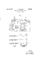
- FIGURE 1 is a simplified circuit diagram of one embodiment according to the invention.
- FIGURE 2 shows explanatory waveforms.
- a television waveform whose black level is to be stabilized in the amplifier A is detected by detector D and applied via terminal T1 to the suppressor grid of a pentode gating valve V1 which is normally cut-off but which is made conducting by the application of line frequency gating pulses to its control grid from the gating pulse source GS via terminal T2.
- These gating pulses have a Width of about 4 to 5 microseconds and may be obtained for example by differentiation and shaping of the line synchronizing pulses of the Waveform.
- the pulse voltage developed across the anode load R1 of the pentode is A.C.
- the clamp circuit CC comprising two diodes D1, D2 which are fed with clamping pulses from the clamping pulse source CS via terminals T3 and T4, to clamp the signal to a DO. reference potential V for approximately 2 microseconds during the back porch period.
- the clamp pulses may be derived from atelevision waveform generator.
- the reference potential V will be chosen to obtain the correct working condition in the valve V2.
- the clamped waveform is then applied to the control grid of this further valve V2 which is arranged as a cathode follower and which is inherently stable, the output from V2 being filtered or smoothed in circuit F to produce a DO control voltage.
- the DC. control voltage is applied to amplifier A over conductor W to control the gain of one or more of its stages so as to stabilize the black level of the television waveform.
- a stable amplifier SA may be added between the gating valve V1 and the control valve V2.
- FIGURE 2 shows explanatory waveforms, and it will be seen that in the circuit according to the present invention the output control voltage is obtained from the long duration positive pulse periods P, which are of the order of the duration of the line periods and are equivalent to the cut-off periods at the anode of the gating valve V1.
- the amplitude of the pulses P depend upon the amplitude of the synchronizing pulses.
- the gating pulses themselves have negligible effect on this control voltage and are not critical in width or time as a variation of say 20% in the pulse width, i.e. a variation of 1 microsecond in a 5 microsecond gating pulse only produces about 1% variation of the long cut-off pulse period P.
- overlap ofthe gating pulses into the synchronizing pulse period has no effect on the output and therefore the phasing of the pulses is not critical. This in turn enables the equipment to be simplified.
- the reference potential may be obtained from'the front porch or the synchronizing pulse tip.
- the gating pulses may still be relatively broad and it is only necessary precisely to time the clamping pulses.
- An automatic gain control circuit for controlling the gain of a television signal amplifier in order to stabilize the black level of a composite television waveform contained in a modulated carrier wave, comprising means for feeding the televisionwaveform to said amplifier, means for detecting the television waveform obtained from the output of said amplifier, a gating device, means for DC. coupling the detected waveform to the gating device, a source of gating pulses, means for feeding the gating pulses to said gating device to gate the television waveform at least during a portion of the television waveform which is capable of providing a reference potential, so as to produce from the gating device a pulse output waveform which extends between the gating periods and which has an amplitude depending upon the DC.
- a clamp circuit means for applying a DC. potential to the clamp circuit, means for A.C. coupling the pulse output waveform from the gating device to the clamp circuit, a clamp pulse source for controlling said clamp circuit to clamp said pulse output waveform from the gating device to the DC. potential applied to said clamp circuit during a part of said reference portion of the television waveform, a filter circuit, means for DC. connecting the clamped r 3 Waveform to said filter circuit to produce a D.C. control voltage and means for feeding said D.C. control voltage to control the gain of said amplifier.
- the gating device consists of a pentode valve having a control grid and a suppressor grid and the detected television waveform is supplied to the suppressor grid whilst the gating pulses are applied to the control grid of the valve.
- An automatic gain control circuit for controlling the gain of a television signal amplifier in order to stabilize the black level of a composite television waveform contained in a modulated carrier wave, comprising means for feeding the television waveform to said amplifier, means for detecting the television waveform obtained from the output of said amplifier, a gating device, means for D.C. coupling the detected waveform to the gating device, a source of gating pulses, means for feeding the gating pulses to said gating device to gate the television waveform at least during a portion of the television waveform which is capable of providing a reference potential, so as to produce from the gating device a pulse output waveform which extends between the gating periods and which has an amplitude depending upon the D.C.
- a clamp circuit means for applying a D.C. potential to the clamp circuit, means for A.C. coupling the pulse output waveform from the gating device to the clamp circuit, a clamp pulse source for controlling said clamp circuit to clamp said pulse output waveform from the gating device to the D.C. potential applied to said clamp circuit during a part of said reference portion of the television waveform, a cathode follower, means for D.C. connecting the clamped waveform to said cathode follower, a filter circuit, means for D.C. connecting the output of said cathode follower to said filter circuit to produce a D.C. control voltage and means for feeding said D.C. control voltage to control the gain of said amplifier.
- An automatic gain control circuit for controlling the gain of a television signal amplifier in order to stabilize the black level of a composite television waveform contained in a modulated carrier wave, comprising means for feeding the television waveform to said amplifier, means for detecting the television waveform obtained from the output of said amplifier, a gating device, means for D.C.
- a source of gating pulses means for feeding the gating pulses to said gating device to gait the television waveform at least during the post synchronizing pulse black level periods of the television waveform, so as to produce from the gating device a pulse output waveform which extends between the gating periods and which has an amplitude depending upon the black level of the tele vision waveform, a clamp circuit, means for applying a.
- D.C. potential to the clamp circuit means for A.C. coupling the pulse output waveform from the gating device to the clamp circuit, a clamp pulse source for controlling said clamp circuit to clamp said pulse output waveform from the gating device to the D.C. potential applied to said clamp circuit during a part of said reference portion of the television waveform, a filter circuit, means for D.C. connecting the clamped waveform to said filter circuit to produce a D.C. control voltage and means for feeding said D.C. control voltage to control the gain of said amplifier.
- the gating device consists of a pentode valve having a control grid and a suppressor grid and the detected television waveform is supplied to the suppressor grid whilst the gating pulses are applied to the control grid of the valve.
- An automatic gain control circuit for controlling the gain of a television signal amplifier in order to stabilize the black level of a composite television Waveform contained in a modulated carrier wave, comprising means for feeding the television waveform to said amplifier, means for detecting the television waveform obtained from the output of said amplifier, a gating device, means for D.C.
- a source of gating pulses means for feeding the gating pulses to said gating device to gate the television waveform at least during the post synchronizing pulse black level periods of the television waveform, so as to produce from the gating device a pulse output waveform which extends between the gating periods and which has an amplitude depending upon the black level of the television waveform, a clamp circuit, means for applying a D.C. potential to the clamp circuit, means for A.C. coupling the pulse output waveform from the gating device to the clamp circuit, a clamp pulse source for controlling said clamp circuit to clamp said pulse output waveform from the gating device to the D.C.
- a cathode follower means for D.C. connecting the clamped waveform to said cathode follower, a filter circuit, means for D.C. connecting the output of said cathode follower to said filter circuit to produce a D.C. control voltage and means for feeding said D.C. control voltage to control the gain of said amplifier.
Landscapes
- Engineering & Computer Science (AREA)
- Multimedia (AREA)
- Signal Processing (AREA)
- Television Receiver Circuits (AREA)
Description
Aug. 18, 1964 c. A. BARNARD 3,145,263
BLACK LEVEL STABILIZATION CIRCUIT Filed Sept. 7, 1961 DETECTOR GATE PULSE SOURCE AMP IFIER L PA CLAMP PULSE cs & y SOURCE (a) VIDEO INPUT T1 L FL (b) EAT/N6 INPUT T2 (0 OUTPUT FROM w W v LJ Inventor CA. Ba rna rd United States Patent ,0
3,145,263 BLACK LEVEL STABILIZATION CIRCUIT Chlford Albert Barnard, Cambridge, England, assignor to Pye Limited, Cambridge, England, a British company Filed Sept. 7, 1961, Ser. No. 136,607
Claims priority, application Great Britain Sept. 3, 1960 Claims. (Cl. 178--7.3)
The present invention relates to a circuit arrangement for obtaining a gain control voltage which may be applied to amplifiers in order to stabilize the black level of a composite video waveform contained in a modulated carrier Wave.
According to the present invention the television waveform obtained from the amplifier output is detected and is D.C. coupled to a gating device where it is gated by means of gating pulses at least during a portion of the television waveform which is capable of providing a reference potential so as to produce a pulse output wave form including a portion whose amplitude depends upon the DC. level of said reference portion of the television waveform, said pulse output waveform being A.C. coupled to a clamp circuit which clamps the output to a preset DC. potential during a part of the said reference portion of the waveform and then being filtered or smoothed to produce a DC. control voltage which is applied to control the gain of said amplifier.
The gating device may consist of a pentode valve and the television waveform be applied to the suppressor grid whilst line frequency gating pulses are applied to its control grid. The gating pulses can be derived from or constitute line synchronizing pulses.
The clamped waveform is preferably fed to the filter circuit through a cathode follower control stage. The
clamp circuit may be controlled by pulses derived from a television waveform generator.
The circuit according to the present invention may be employed both in television transmitters and in television receivers.
As applied to transmitters the video signal is obtained by sampling the output of the transmitter and a stable amplifying circuit may be included between the gating device and the control device. The D.C. control voltage may be applied to the modulator of the transmitter to compensate for variations in the emission of the radio frequency amplifier or amplifiers. Alternatively the DC. control voltage maybe applied to one or more RF. stages of the transmitter which are selected to function in addition as a control stage or stages to compensate for variations in the emission or performance of the R.F. amplifier v chain as a whole.
In a television receiver the DC. control voltage may be employed as an automatic gain control voltage acting on the radio frequency or intermediate frequency amplifying stages of the receiver.
The invention will now be further described with reference to the accompanying drawing, in which:
FIGURE 1 is a simplified circuit diagram of one embodiment according to the invention, and
FIGURE 2 shows explanatory waveforms.
Referring to the drawing, a television waveform whose black level is to be stabilized in the amplifier A, is detected by detector D and applied via terminal T1 to the suppressor grid of a pentode gating valve V1 which is normally cut-off but which is made conducting by the application of line frequency gating pulses to its control grid from the gating pulse source GS via terminal T2. These gating pulses have a Width of about 4 to 5 microseconds and may be obtained for example by differentiation and shaping of the line synchronizing pulses of the Waveform. The pulse voltage developed across the anode load R1 of the pentode is A.C. coupled through condenser C1 to the clamp circuit CC comprising two diodes D1, D2 which are fed with clamping pulses from the clamping pulse source CS via terminals T3 and T4, to clamp the signal to a DO. reference potential V for approximately 2 microseconds during the back porch period. The clamp pulses may be derived from atelevision waveform generator. The reference potential V will be chosen to obtain the correct working condition in the valve V2. The clamped waveform is then applied to the control grid of this further valve V2 which is arranged as a cathode follower and which is inherently stable, the output from V2 being filtered or smoothed in circuit F to produce a DO control voltage. The DC. control voltage is applied to amplifier A over conductor W to control the gain of one or more of its stages so as to stabilize the black level of the television waveform.
Where the circuit is employed in transmitters a stable amplifier SA may be added between the gating valve V1 and the control valve V2.
FIGURE 2 shows explanatory waveforms, and it will be seen that in the circuit according to the present invention the output control voltage is obtained from the long duration positive pulse periods P, which are of the order of the duration of the line periods and are equivalent to the cut-off periods at the anode of the gating valve V1. The amplitude of the pulses P depend upon the amplitude of the synchronizing pulses. The gating pulses themselves have negligible effect on this control voltage and are not critical in width or time as a variation of say 20% in the pulse width, i.e. a variation of 1 microsecond in a 5 microsecond gating pulse only produces about 1% variation of the long cut-off pulse period P. Furthermore overlap ofthe gating pulses into the synchronizing pulse period has no effect on the output and therefore the phasing of the pulses is not critical. This in turn enables the equipment to be simplified.
Whilst a particular embodiment has been described it will be understood that various modifications may be made without departing from the scope of this invention. For example where a color television signal is being stabilized and a color synchronizing HF. burst is present in the back porch period, the reference potential may be obtained from'the front porch or the synchronizing pulse tip. The gating pulses may still be relatively broad and it is only necessary precisely to time the clamping pulses.
I claim:
1. An automatic gain control circuit for controlling the gain of a television signal amplifier in order to stabilize the black level of a composite television waveform contained in a modulated carrier wave, comprising means for feeding the televisionwaveform to said amplifier, means for detecting the television waveform obtained from the output of said amplifier, a gating device, means for DC. coupling the detected waveform to the gating device, a source of gating pulses, means for feeding the gating pulses to said gating device to gate the television waveform at least during a portion of the television waveform which is capable of providing a reference potential, so as to produce from the gating device a pulse output waveform which extends between the gating periods and which has an amplitude depending upon the DC. level of the reference portion of the television waveform, a clamp circuit, means for applying a DC. potential to the clamp circuit, means for A.C. coupling the pulse output waveform from the gating device to the clamp circuit, a clamp pulse source for controlling said clamp circuit to clamp said pulse output waveform from the gating device to the DC. potential applied to said clamp circuit during a part of said reference portion of the television waveform, a filter circuit, means for DC. connecting the clamped r 3 Waveform to said filter circuit to produce a D.C. control voltage and means for feeding said D.C. control voltage to control the gain of said amplifier.
2. A circuit arrangement as claimed in claim 1, in which the gating device consists of a pentode valve having a control grid and a suppressor grid and the detected television waveform is supplied to the suppressor grid whilst the gating pulses are applied to the control grid of the valve.
3. A circuit as claimed in claim 1, in which a stable amplifying circuit is included between the gating device and the clamp circuit.
4. A circuit as claimed in claim 1, in which the gating pulses are derived from the line frequency synchronizing pulses of the television waveform.
S. An automatic gain control circuit for controlling the gain of a television signal amplifier in order to stabilize the black level of a composite television waveform contained in a modulated carrier wave, comprising means for feeding the television waveform to said amplifier, means for detecting the television waveform obtained from the output of said amplifier, a gating device, means for D.C. coupling the detected waveform to the gating device, a source of gating pulses, means for feeding the gating pulses to said gating device to gate the television waveform at least during a portion of the television waveform which is capable of providing a reference potential, so as to produce from the gating device a pulse output waveform which extends between the gating periods and which has an amplitude depending upon the D.C. level of the reference portion of the television waveform, a clamp circuit, means for applying a D.C. potential to the clamp circuit, means for A.C. coupling the pulse output waveform from the gating device to the clamp circuit, a clamp pulse source for controlling said clamp circuit to clamp said pulse output waveform from the gating device to the D.C. potential applied to said clamp circuit during a part of said reference portion of the television waveform, a cathode follower, means for D.C. connecting the clamped waveform to said cathode follower, a filter circuit, means for D.C. connecting the output of said cathode follower to said filter circuit to produce a D.C. control voltage and means for feeding said D.C. control voltage to control the gain of said amplifier.
6. An automatic gain control circuit for controlling the gain of a television signal amplifier in order to stabilize the black level of a composite television waveform contained in a modulated carrier wave, comprising means for feeding the television waveform to said amplifier, means for detecting the television waveform obtained from the output of said amplifier, a gating device, means for D.C. coupling the detected waveform to the gating device, a source of gating pulses, means for feeding the gating pulses to said gating device to gait the television waveform at least during the post synchronizing pulse black level periods of the television waveform, so as to produce from the gating device a pulse output waveform which extends between the gating periods and which has an amplitude depending upon the black level of the tele vision waveform, a clamp circuit, means for applying a.
D.C. potential to the clamp circuit, means for A.C. coupling the pulse output waveform from the gating device to the clamp circuit, a clamp pulse source for controlling said clamp circuit to clamp said pulse output waveform from the gating device to the D.C. potential applied to said clamp circuit during a part of said reference portion of the television waveform, a filter circuit, means for D.C. connecting the clamped waveform to said filter circuit to produce a D.C. control voltage and means for feeding said D.C. control voltage to control the gain of said amplifier.
7. A circuit arrangement as claimed in claim 6, in which the gating device consists of a pentode valve having a control grid and a suppressor grid and the detected television waveform is supplied to the suppressor grid whilst the gating pulses are applied to the control grid of the valve.
8. A circuit as claimed in claim 6, in which a stable amplifying circuit is included between the gating device and the clamp circuit.
9. A circuit as claimed in claim 6, in which the gating pulses are derived from the line frequency synchronizing pulses of the television waveform.
10. An automatic gain control circuit for controlling the gain of a television signal amplifier in order to stabilize the black level of a composite television Waveform contained in a modulated carrier wave, comprising means for feeding the television waveform to said amplifier, means for detecting the television waveform obtained from the output of said amplifier, a gating device, means for D.C. coupling the detected waveform to the gating device, a source of gating pulses, means for feeding the gating pulses to said gating device to gate the television waveform at least during the post synchronizing pulse black level periods of the television waveform, so as to produce from the gating device a pulse output waveform which extends between the gating periods and which has an amplitude depending upon the black level of the television waveform, a clamp circuit, means for applying a D.C. potential to the clamp circuit, means for A.C. coupling the pulse output waveform from the gating device to the clamp circuit, a clamp pulse source for controlling said clamp circuit to clamp said pulse output waveform from the gating device to the D.C. potential applied to said clamp circuit during a part of said reference portion of the television waveform, a cathode follower, means for D.C. connecting the clamped waveform to said cathode follower, a filter circuit, means for D.C. connecting the output of said cathode follower to said filter circuit to produce a D.C. control voltage and means for feeding said D.C. control voltage to control the gain of said amplifier.
References Cited in the file of this patent UNITED STATES PATENTS 2,792,496 Rhodes May 14, 1957 2,934,602 Cope et al. Apr. 26, 1960 FOREIGN PATENTS 649,141 Great Britain Jan. 17, 1951
Claims (1)
1. AN AUTOMATIC GAIN CONTROL CIRCUIT FOR CONTROLLING THE GAIN OF A TELEVISION SIGNAL AMPLIFIER IN ORDER TO STABILIZE THE BLACK LEVEL OF A COMPOSITE TELEVISION WAVEFORM CONTAINED IN A MODULATED CARRIER WAVE, COMPRISING MEANS FOR FEEDING THE TELEVISION WAVEFORM TO SAID AMPLIFIER, MEANS FOR DETECTING THE TELEVISION WAVEFORM OBTAINED FROM THE OUTPUT OF SAID AMPLIFIER, A GATING DEVICE, MEANS FOR D.C. COUPLING THE DETECTED WAVEFORM TO THE GATING DEVICE, A SOURCE OF GATING PULSES, MEANS FOR FEEDING THE GATING PULSES TO SAID GATING DEVICE TO GATE THE TELEVISION WAVEFORM AT LEAST DURING A PORTION OF THE TELEVISION WAVEFORM WHICH IS CAPABLE OF PROVIDING A REFERENCE POTENTIAL, SO AS TO PRODUCE FROM THE GATING DEVICE A PULSE OUTPUT WAVEFORM WHICH EXTENDS BETWEEN THE GATING PERIODS AND WHICH HAS AN AMPLITUDE DEPENDING UPON THE D.C. LEVEL OF THE REFERENCE PORTION OF THE TELEVISION WAVEFORM, A CLAMP CIRCUIT, MEANS FOR APPLYING A D.C. POTENTIAL TO THE CLAMP CIRCUIT, MEANS FOR A.C. COUPLING THE PULSE OUTPUT WAVEFORM FROM THE GATING DEVICE TO THE CLAMP CIRCUIT, A CLAMP PULSE SOURCE FOR CONTROLLING SAID CLAMP CIRCUIT TO CLAMP SAID PULSE OUTPUT WAVEFORM FROM THE GATING DEVICE TO THE D.C. POTENTIAL APPLIED TO SAID CLAMP CIRCUIT DURING A PART OF SAID REFERENCE PORTION OF THE TELEVISION WAVEFORM, A FILTER CIRCUIT, MEANS FOR D.C. CONNECTING THE CLAMPED WAVEFORM TO SAID FILTER CIRCUIT TO PRODUCE A D.C. CONTROL VOLTAGE AND MEANS FOR FEEDING SAID D.C. CONTROL VOLTAGE TO CONTROL THE GAIN OF SAID AMPLIFIER.
Applications Claiming Priority (1)
| Application Number | Priority Date | Filing Date | Title |
|---|---|---|---|
| GB31505/60A GB910854A (en) | 1960-09-13 | 1960-09-13 | Black level stabilisation circuit |
Publications (1)
| Publication Number | Publication Date |
|---|---|
| US3145263A true US3145263A (en) | 1964-08-18 |
Family
ID=10324099
Family Applications (1)
| Application Number | Title | Priority Date | Filing Date |
|---|---|---|---|
| US136607A Expired - Lifetime US3145263A (en) | 1960-09-13 | 1961-09-07 | Black level stabilization circuit |
Country Status (2)
| Country | Link |
|---|---|
| US (1) | US3145263A (en) |
| GB (1) | GB910854A (en) |
Cited By (5)
| Publication number | Priority date | Publication date | Assignee | Title |
|---|---|---|---|---|
| US3292096A (en) * | 1964-05-11 | 1966-12-13 | Jr Raymond J Deneen | Linear, automatic gain control amplifier |
| US3358155A (en) * | 1964-10-30 | 1967-12-12 | Tektronix Inc | Gating circuit having gating oscillator with internal time delay |
| US4215371A (en) * | 1978-12-21 | 1980-07-29 | Rockwell International Corporation | Front porch clamping circuit |
| US4261015A (en) * | 1979-07-09 | 1981-04-07 | Burroughs Corporation | Video clamp |
| US4943859A (en) * | 1988-07-27 | 1990-07-24 | Mitsubishi Denki Kabushiki Kaisha | Circuit for producing clamp pulse having pulse width response to the frequency of a synchronizing signal |
Citations (3)
| Publication number | Priority date | Publication date | Assignee | Title |
|---|---|---|---|---|
| GB649141A (en) * | 1947-02-26 | 1951-01-17 | Marconi Wireless Telegraph Co | Improvements relating to gain control circuits for television receiving apparatus |
| US2792496A (en) * | 1953-09-24 | 1957-05-14 | Rca Corp | Stabilized direct current setting apparatus |
| US2934602A (en) * | 1954-02-09 | 1960-04-26 | Pye Ltd | Television receivers |
-
1960
- 1960-09-13 GB GB31505/60A patent/GB910854A/en not_active Expired
-
1961
- 1961-09-07 US US136607A patent/US3145263A/en not_active Expired - Lifetime
Patent Citations (3)
| Publication number | Priority date | Publication date | Assignee | Title |
|---|---|---|---|---|
| GB649141A (en) * | 1947-02-26 | 1951-01-17 | Marconi Wireless Telegraph Co | Improvements relating to gain control circuits for television receiving apparatus |
| US2792496A (en) * | 1953-09-24 | 1957-05-14 | Rca Corp | Stabilized direct current setting apparatus |
| US2934602A (en) * | 1954-02-09 | 1960-04-26 | Pye Ltd | Television receivers |
Cited By (5)
| Publication number | Priority date | Publication date | Assignee | Title |
|---|---|---|---|---|
| US3292096A (en) * | 1964-05-11 | 1966-12-13 | Jr Raymond J Deneen | Linear, automatic gain control amplifier |
| US3358155A (en) * | 1964-10-30 | 1967-12-12 | Tektronix Inc | Gating circuit having gating oscillator with internal time delay |
| US4215371A (en) * | 1978-12-21 | 1980-07-29 | Rockwell International Corporation | Front porch clamping circuit |
| US4261015A (en) * | 1979-07-09 | 1981-04-07 | Burroughs Corporation | Video clamp |
| US4943859A (en) * | 1988-07-27 | 1990-07-24 | Mitsubishi Denki Kabushiki Kaisha | Circuit for producing clamp pulse having pulse width response to the frequency of a synchronizing signal |
Also Published As
| Publication number | Publication date |
|---|---|
| GB910854A (en) | 1962-11-21 |
Similar Documents
| Publication | Publication Date | Title |
|---|---|---|
| US2564017A (en) | Clamp circuit | |
| US2801364A (en) | Circuit-arrangement in which a signal is supplied to a control-device | |
| GB681331A (en) | Improvements in combination automatic gain control and amplitude discriminatory circuits for radio reception | |
| US3145263A (en) | Black level stabilization circuit | |
| GB1413269A (en) | Aperture correction of video signals | |
| GB1410966A (en) | Beam current control systems for picutre tubes | |
| US4513321A (en) | Black level clamp for television signals | |
| GB1458450A (en) | Keyed agc circuit | |
| GB1289082A (en) | ||
| US3109061A (en) | Noise cut-off agc and sync-separator tubes | |
| GB768508A (en) | Signal-separating circuit for a color-television receiver | |
| US2950342A (en) | Signal separation circuits | |
| US3619648A (en) | Circuit arrangement for restoring the direct-current component by the control of a reference value | |
| US2540512A (en) | Interference reducing impulse amplitude detector | |
| GB971005A (en) | Chrominance channel control apparatus | |
| GB991761A (en) | Improvements in and relating to colour television apparatus | |
| GB1026585A (en) | Improvements in or relating to circuit arrangements in colour television receivers | |
| GB1307350A (en) | Automatic beam focusing system | |
| US2956153A (en) | Electrical noise reduction techniques | |
| GB1445159A (en) | Synchronous detection | |
| GB797810A (en) | Improvements in or relating to pulse controlled electrical circuit arrangements | |
| GB970672A (en) | Automatic-gain-control system | |
| GB2058513A (en) | Circuit for inhibiting radio frequency interference in a television receiver | |
| GB1289286A (en) | ||
| US2832822A (en) | Kinescope coupling and control circuits |