US3155154A - Air seal for rotary heat exchanger - Google Patents
Air seal for rotary heat exchanger Download PDFInfo
- Publication number
- US3155154A US3155154A US90511A US9051161A US3155154A US 3155154 A US3155154 A US 3155154A US 90511 A US90511 A US 90511A US 9051161 A US9051161 A US 9051161A US 3155154 A US3155154 A US 3155154A
- Authority
- US
- United States
- Prior art keywords
- rotor
- end plate
- valve
- sealing
- radial
- Prior art date
- Legal status (The legal status is an assumption and is not a legal conclusion. Google has not performed a legal analysis and makes no representation as to the accuracy of the status listed.)
- Expired - Lifetime
Links
- 238000007789 sealing Methods 0.000 claims description 43
- 238000005192 partition Methods 0.000 claims description 18
- 230000001172 regenerating effect Effects 0.000 claims description 12
- 239000000463 material Substances 0.000 claims description 7
- 238000010438 heat treatment Methods 0.000 claims description 6
- 230000002745 absorbent Effects 0.000 claims description 5
- 239000002250 absorbent Substances 0.000 claims description 5
- 239000007789 gas Substances 0.000 description 18
- 239000012530 fluid Substances 0.000 description 8
- 238000005299 abrasion Methods 0.000 description 3
- 230000004888 barrier function Effects 0.000 description 2
- 238000002485 combustion reaction Methods 0.000 description 1
- 230000008602 contraction Effects 0.000 description 1
- 230000001419 dependent effect Effects 0.000 description 1
- 230000000694 effects Effects 0.000 description 1
- 238000012986 modification Methods 0.000 description 1
- 230000004048 modification Effects 0.000 description 1
Images

Classifications
-
- F—MECHANICAL ENGINEERING; LIGHTING; HEATING; WEAPONS; BLASTING
- F28—HEAT EXCHANGE IN GENERAL
- F28D—HEAT-EXCHANGE APPARATUS, NOT PROVIDED FOR IN ANOTHER SUBCLASS, IN WHICH THE HEAT-EXCHANGE MEDIA DO NOT COME INTO DIRECT CONTACT
- F28D19/00—Regenerative heat-exchange apparatus in which the intermediate heat-transfer medium or body is moved successively into contact with each heat-exchange medium
- F28D19/04—Regenerative heat-exchange apparatus in which the intermediate heat-transfer medium or body is moved successively into contact with each heat-exchange medium using rigid bodies, e.g. mounted on a movable carrier
- F28D19/047—Sealing means
-
- Y—GENERAL TAGGING OF NEW TECHNOLOGICAL DEVELOPMENTS; GENERAL TAGGING OF CROSS-SECTIONAL TECHNOLOGIES SPANNING OVER SEVERAL SECTIONS OF THE IPC; TECHNICAL SUBJECTS COVERED BY FORMER USPC CROSS-REFERENCE ART COLLECTIONS [XRACs] AND DIGESTS
- Y10—TECHNICAL SUBJECTS COVERED BY FORMER USPC
- Y10S—TECHNICAL SUBJECTS COVERED BY FORMER USPC CROSS-REFERENCE ART COLLECTIONS [XRACs] AND DIGESTS
- Y10S165/00—Heat exchange
- Y10S165/009—Heat exchange having a solid heat storage mass for absorbing heat from one fluid and releasing it to another, i.e. regenerator
- Y10S165/013—Movable heat storage mass with enclosure
- Y10S165/016—Rotary storage mass
- Y10S165/026—Seal attached to and rotating with storage mass
Definitions
- the present invention relates to rotary regenerative heat exchange apparatus and especially it relates to sealing means for such apparatus adapted to preclude fluid flow between fixed and relatively rotatable parts thereof. Apparatus of the type herein defined is discolsed generally in US. Patent 2,674,442 wherein a predetermined clearance space is maintained between relatively movable sealing parts of a rotary regenerative heat exchanger to obtain an optimum sealing relationship therebetween.
- a rotary regenerative heat exchanger has a rotor including a cylindrical shell joined to a rotor post by radial partitions that form sectorial compartments carrying heat absorbent material that is alternately contacted by hot gas and cooler air.
- the rotor is surrounded by a rotor housing having end or sector plates formed with openings that provide passage for the fluids.
- the partitions of the rotor are provided with radial seals and the cylindrical rotor shell is provided with a circumferential seal that cooperates with the stationary parts of the rotor housing to pre clude fluid flow therebetween.
- the principle object of this invention therefore is to provide a sealing arrangement of maximum effectiveness that is accompanied by a minimum of seal drag and abrasion. Stated otherwise an object of my invention is to provide a clearance sealing arrangement for a rotary regenerative heat exchanger that has a near maximum cite"- tiveness.
- the present invention contemplates constructing the sealing members with means that maintains a slight predetermined clearance with the sector plates despite relative movement of the rotor and rotor housing due to nonuniform expansion and contraction of their various structural parts. To preclude leakage of fluid through the clearance space thus provided between the sealing members and sector plate the invention further provides for an arrangement by which this space is continuously supplied with a quantity of air or other gaseous fluid at a pressure substantially above that of the fluids being sealed.
- FIGURE 1 is a perspective view in diagrammatic form illustrating a rotary regenerative heat exchanger involving the present invention.
- FIGURE 2 is a top plan view of an end plate arrangement as viewed from 2-2 of FIGURE 1.
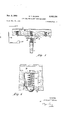
- FIGURE 3 is an enlarged View of the end plate and sealing arrangement as seen from 33 of FIGURE 2.
- FIGURE 4 is an enlarged detail drawing showing an in' dividual ball check valve arrangement shown in FIG- URE 3.
- the numeral 10 designates the cylindri-' cal shell of a rotor divided into sector shaped compartments by radial partitions 11 which connect the shell to a rotor post 12 that is in turn driven about its axis by a motor and reduction gear arrangement or other means not illustrated.
- the rotor compartments contain regenerative heat transfer material in the form of closely spaced metallic plates 14 which first absorb heat from hot gases entering the heat exchanger through a duct 15 from a boiler or other source to be discharged, after passing over the heat transfer plates 14, through an outlet duct 16 to which an induced draft fan (not illustrated) is connected.
- the heated plates 1% are moved into the stream of air admitted through the duct 1'7, and after passing over the plates 14 and absorbing heat therefrom the stream of heated air is conveyed to the boiler furnace or other place of use through an outlet duct 18.
- a housing 20 enclosing the rotor 10 is provided at either end with end or sector plates 21 which are apertured at 22 and 23 to admit and discharge streams of gas and air flowing through the heat exchanger in countercurrent relationship.
- radial seals 25 are provided along the end edges of the diaphragms and circumfer-- ential seals are provided at the end edges of the rotor shell to retard the flow of air or gas therethrough and seal off the annular space 24 from the rest of the rotor.
- sealing arrangement suitable for either circumferential or radial application in a rotary regenerative heat exchanger. Since the sealing arrangement of this invention is however particularly adapted for use in applications requiring intermittent operation as when utilized as a radial seal, the following specification will be directed most particularly to such an application.
- an axially movable radial sealing member is mounted on the end edge of each radial partition and biased towards the confronting face of adjacent end plate 21 by a spring 32.
- Each sealing member comprises essentially a pair of oppositely facing angle members 34 having a sealing shoe 38 attached to the upper surface of their oppositely extending arms.
- the angle members 34 slidably embrace the opposite sides of each radial partition 11 While the space 35 between angle members and above the end edge of the radial partition is advantageously utilized as a housing for spring means 32.
- the spring means 32 is considered exemplary of one type of actuation available and equivalent means such as leaf springs or weighted lever arrangements may be similarly used.
- the sealing shoe 38 is preferably made of hardened material not readily subject to deformation or the effects of abrasion. When used in a radial application as illustrated in FIGURE 3, it is formed with chamfered or rounded edges 42 at the sides of a substantially flat surface 44.
- each end plate 21 lying between a ertures 22 and 23 a series of ports 45 are drilled and tapped to receive an apertured valve seat 46.
- the ports 45 are disposed across the surface of the end plate in such a manner that one or more of said ports are at all times in axial alignment with the sealing shoe 33 carried by the radial partitions of the rotor.
- the valve seat carries a ball check valve 48 which is in turn is held against its seat by a spring -9.
- a passageway 52 connects each port 45 to a common air chamber 54 that is continuously supplied with compressed air from an independent source 55 by a duct 56 at a pressure in excess of that flowing through the heat exchanger.
- the check valve 48 in each port 44 protrudes axially through its seat 46 into the space between rotor and end plate 21 to provide an actuating means for raising the valve 48 off its seat 4 5 when the radial sealing shoe 38 is moved into axial alignment therewith.
- Rotary regenerative heat exchange apparatus having a rotor including a cylindrical shell joined to a rotor post by radial partitions to form a series of sectorial compartments therebetween; a mass of heat absorbent material carried in each compartment of the rotor; at housing surrounding the rotor provided at opposite ends thereof with end plates axially spaced from the edge of the radial partitions and formed with circumferentially spaced apertures between imperforate portions to permit the flow of heating gas and air to and through the rotor; a plurality of ports through the imperforate portion of each end plate; a source of gas under pressure; duct means connecting the source of gas to said ports in the end plate;
- valve seat in each end plate port adjacent the rotor; a check valve; means resiliently holding said valve on said seat; axially movable sealing means carried on the end edge of each radial partition; means biasing said sealing means toward the confronting surface of said end plate whereby rotation of the rotor moves the end edges of said sealing means into contacting relation with the valve means to move said valve from its seat and permit gas under pressure to fiow into the space between the sealing means and end plate.
- Rotary regenerative heat exchange apparatus having a rotor including a cylindrical shell joined to a rotor post by radial partitions to form a series of sectorial compartments therebetween; a mass of heat absorbent material carried in each compartment of the rotor; a housing surrounding the rotor provided at opposite ends thereof with end plates axially spaced from the end edges of the radial partitions and formed with circumferentially spaced apertures between imperforate portions to permit the flow of heating gas and air to and through the rotor; a plurality of ports in the imperforate portion of each end plate; a source of gas under pressure; means connecting the source of gas to said ports in the end late; a valve seat in each port; a check valve; means resiliently holding the check valve on said seat; axially movable sealing means carried on the end edge of each radial partition; and biasing means resiliently forcing said sealing means towards the adjacent end plate to sequentially move each check valve from its seat and direct the flow of gas under pressure to the space between the end plate
- Rotary regenerative heat exchange apparatus having a rotor including a cylindrical shell joined to a rotor post by radial partitions to form a series of sectorial compartments therebetween; a mass of heat absorbent material carried in each compartment of the rotor; a housing surroundin the rotor provided at opposite ends thereof with end plates axially spaced from the end edges of the radial partitions and formed with circumferentially spaced apertures between imperforate portions to permit the flow of heating gas and air to and through the rotor; radial sealing means on the end edge of the radial partitions; biasing means exerting a force on said radial sealing means in the direction of the adjacent end plate; a source of compressed air; and means responsive to axial movement of said radial sealing means adapted to direct a flow of compressed air from said source to the space between the radial sealing means and adjacent surface of said end plate whereby said compressed air may exert a force on the radial sealing means that counterbalances the force of said biasing means.
Landscapes
- Engineering & Computer Science (AREA)
- Physics & Mathematics (AREA)
- Thermal Sciences (AREA)
- Mechanical Engineering (AREA)
- General Engineering & Computer Science (AREA)
- Heat-Exchange Devices With Radiators And Conduit Assemblies (AREA)
Description
Nov. 3, 1964 E. T. WILSON AIR SEAL FOR ROTARY HEAT EXCHANGER Filed Feb. 20, 1961 2 Sheets-Sheet 1 Nov. 3, 1964 E. T. WILSON 3,155,154
AIR SEAL FOR ROTARY HEAT EXCHANGER Filed Feb. 20 1961 2 Sheets-Sheet 2 United States Patent 3,155,154 AIR SEAL FUR RD'IARY HEAT EXCHANGER Edward T. t ilson, Andover, N.Y., asslgnor, by mesne assignments, to Combustion Engineering, line, a stock corporation of Belaware Filed Feb. 20, li -61, Ser. No. 90,511 3 (Iiairns. (Cl. 165-9) The present invention relates to rotary regenerative heat exchange apparatus and especially it relates to sealing means for such apparatus adapted to preclude fluid flow between fixed and relatively rotatable parts thereof. Apparatus of the type herein defined is discolsed generally in US. Patent 2,674,442 wherein a predetermined clearance space is maintained between relatively movable sealing parts of a rotary regenerative heat exchanger to obtain an optimum sealing relationship therebetween.
A rotary regenerative heat exchanger has a rotor including a cylindrical shell joined to a rotor post by radial partitions that form sectorial compartments carrying heat absorbent material that is alternately contacted by hot gas and cooler air. The rotor is surrounded by a rotor housing having end or sector plates formed with openings that provide passage for the fluids. To prevent mingling of the hot gas and cooler air the partitions of the rotor are provided with radial seals and the cylindrical rotor shell is provided with a circumferential seal that cooperates with the stationary parts of the rotor housing to pre clude fluid flow therebetween.
Since the effectiveness of a sealing arrangement is primarily dependent upon maintaining a minimum clearance space between relatively movable members, a rubbing or contact type seal is frequently employed. Such an arrangement while providing an effective sealing relationship also produces frictional conditions that induce excessive rubbing of the moving parts that rapidly abrades the rubbing surfaces and produces a drag or braking action requiring substantial power to overcome.
If however, a seal is arranged with a clearance between relatively moving parts to eliminate friction and thus eliminate abrasion of the rubbing surfaces and its attendant braking action, there will be an increase of fluid leakage between sealing members that results in a reduction of seal effectiveness.
The principle object of this invention therefore is to provide a sealing arrangement of maximum effectiveness that is accompanied by a minimum of seal drag and abrasion. Stated otherwise an object of my invention is to provide a clearance sealing arrangement for a rotary regenerative heat exchanger that has a near maximum cite"- tiveness.
The present invention contemplates constructing the sealing members with means that maintains a slight predetermined clearance with the sector plates despite relative movement of the rotor and rotor housing due to nonuniform expansion and contraction of their various structural parts. To preclude leakage of fluid through the clearance space thus provided between the sealing members and sector plate the invention further provides for an arrangement by which this space is continuously supplied with a quantity of air or other gaseous fluid at a pressure substantially above that of the fluids being sealed.
The invention will be best understood upon consideration of the following detailed description of an illustrative embodiment thereof when read in conjunction with the ac companying drawings in which:
FIGURE 1 is a perspective view in diagrammatic form illustrating a rotary regenerative heat exchanger involving the present invention.
FIGURE 2 is a top plan view of an end plate arrangement as viewed from 2-2 of FIGURE 1.
FIGURE 3 is an enlarged View of the end plate and sealing arrangement as seen from 33 of FIGURE 2.
FIGURE 4 is an enlarged detail drawing showing an in' dividual ball check valve arrangement shown in FIG- URE 3.
In the drawing the numeral 10 designates the cylindri-' cal shell of a rotor divided into sector shaped compartments by radial partitions 11 which connect the shell to a rotor post 12 that is in turn driven about its axis by a motor and reduction gear arrangement or other means not illustrated. The rotor compartments contain regenerative heat transfer material in the form of closely spaced metallic plates 14 which first absorb heat from hot gases entering the heat exchanger through a duct 15 from a boiler or other source to be discharged, after passing over the heat transfer plates 14, through an outlet duct 16 to which an induced draft fan (not illustrated) is connected. As the rotor turns slowly about its axis the heated plates 1% are moved into the stream of air admitted through the duct 1'7, and after passing over the plates 14 and absorbing heat therefrom the stream of heated air is conveyed to the boiler furnace or other place of use through an outlet duct 18.
A housing 20 enclosing the rotor 10 is provided at either end with end or sector plates 21 which are apertured at 22 and 23 to admit and discharge streams of gas and air flowing through the heat exchanger in countercurrent relationship.
In order that the streams of gas and air may not intermix or by-pass the rotor, radial seals 25 are provided along the end edges of the diaphragms and circumfer-- ential seals are provided at the end edges of the rotor shell to retard the flow of air or gas therethrough and seal off the annular space 24 from the rest of the rotor.
In defining the invention more particularly, it may be disclosed as a sealing arrangement suitable for either circumferential or radial application in a rotary regenerative heat exchanger. Since the sealing arrangement of this invention is however particularly adapted for use in applications requiring intermittent operation as when utilized as a radial seal, the following specification will be directed most particularly to such an application.
In accordance with the invention an axially movable radial sealing member is mounted on the end edge of each radial partition and biased towards the confronting face of adjacent end plate 21 by a spring 32. Each sealing member comprises essentially a pair of oppositely facing angle members 34 having a sealing shoe 38 attached to the upper surface of their oppositely extending arms. The angle members 34 slidably embrace the opposite sides of each radial partition 11 While the space 35 between angle members and above the end edge of the radial partition is advantageously utilized as a housing for spring means 32. The spring means 32 is considered exemplary of one type of actuation available and equivalent means such as leaf springs or weighted lever arrangements may be similarly used.
The sealing shoe 38 is preferably made of hardened material not readily subject to deformation or the effects of abrasion. When used in a radial application as illustrated in FIGURE 3, it is formed with chamfered or rounded edges 42 at the sides of a substantially flat surface 44.
In the confronting surface of each end plate 21 lying between a ertures 22 and 23 a series of ports 45 are drilled and tapped to receive an apertured valve seat 46. The ports 45 are disposed across the surface of the end plate in such a manner that one or more of said ports are at all times in axial alignment with the sealing shoe 33 carried by the radial partitions of the rotor. The valve seat carries a ball check valve 48 which is in turn is held against its seat by a spring -9. A passageway 52 connects each port 45 to a common air chamber 54 that is continuously supplied with compressed air from an independent source 55 by a duct 56 at a pressure in excess of that flowing through the heat exchanger. The check valve 48 in each port 44 protrudes axially through its seat 46 into the space between rotor and end plate 21 to provide an actuating means for raising the valve 48 off its seat 4 5 when the radial sealing shoe 38 is moved into axial alignment therewith.
In operation a supply of air under pressure is admitted to air chambers 54. Since each sealing shoe 38 is biased against the surface of adjacent end plate 21 by the force of springs 34, rotation of the rotor will sequentially move each sealing shoe against each of the ball check valves 48 that is pressed to its seat by the spring 5%. Upon contact with the shoe 33 each ball check valve will be raised from its seat while air under pressure from chamber 54 will be supplied to the space between the sealing shoe and adjacent end plate 21. When air under pressure is admitted to the space between the sealing shoe and adjacent end plate the air exerts a force on the face of the sealing shoe that counterbalances the upward force of the springs 32 to produce a slight clearance space that precludes frictional contact therebetween. This space is thus charged with air from chamber 54 at a pressure greater than that of the heating gas or air to be heated that is simultaneously being directed through the spaced ducts of the heat exchanger.
Thus a film of compressed air is maintained in the space between the plane surface 44 and confronting surface of end plate 21 to at all times provide a barrier to the flow of gas between spaced fluid passageways of a rotary regenerative heat exchanger. Due to the necessity of spacing the ball check valves 48 in the end plates 21 there may be short intervals during each revolution of the rotor when fewer than an optimum number of valves will be actuated to supply high pressure sealing air to the space between the end plate 21 and the sealing surface 44.. However, by selectively spacing the check valves in the end plates 21 such intervals may be held to a minimum and the overall sealing effectiveness of the apparatus will not be appreciably affected.
While this invention has been described with reference to the embodiment illustrated in the drawing, it is evident that various modifications may be made without departing from the spirit of the invention. It is therefore intended that all matter contained in the above description or shown in the accompanying drawings shall be interpreted as illustrative and not in a limiting sense.
What I claim is:
1. Rotary regenerative heat exchange apparatus having a rotor including a cylindrical shell joined to a rotor post by radial partitions to form a series of sectorial compartments therebetween; a mass of heat absorbent material carried in each compartment of the rotor; at housing surrounding the rotor provided at opposite ends thereof with end plates axially spaced from the edge of the radial partitions and formed with circumferentially spaced apertures between imperforate portions to permit the flow of heating gas and air to and through the rotor; a plurality of ports through the imperforate portion of each end plate; a source of gas under pressure; duct means connecting the source of gas to said ports in the end plate;
a valve seat in each end plate port adjacent the rotor; a check valve; means resiliently holding said valve on said seat; axially movable sealing means carried on the end edge of each radial partition; means biasing said sealing means toward the confronting surface of said end plate whereby rotation of the rotor moves the end edges of said sealing means into contacting relation with the valve means to move said valve from its seat and permit gas under pressure to fiow into the space between the sealing means and end plate.
2. Rotary regenerative heat exchange apparatus having a rotor including a cylindrical shell joined to a rotor post by radial partitions to form a series of sectorial compartments therebetween; a mass of heat absorbent material carried in each compartment of the rotor; a housing surrounding the rotor provided at opposite ends thereof with end plates axially spaced from the end edges of the radial partitions and formed with circumferentially spaced apertures between imperforate portions to permit the flow of heating gas and air to and through the rotor; a plurality of ports in the imperforate portion of each end plate; a source of gas under pressure; means connecting the source of gas to said ports in the end late; a valve seat in each port; a check valve; means resiliently holding the check valve on said seat; axially movable sealing means carried on the end edge of each radial partition; and biasing means resiliently forcing said sealing means towards the adjacent end plate to sequentially move each check valve from its seat and direct the flow of gas under pressure to the space between the end plate and adjacent sealing means to counterbalance the upward force of said biasing means on the radial partitions and simultaneously provide a barrier to the leakage of said heating gas and air.
3. Rotary regenerative heat exchange apparatus having a rotor including a cylindrical shell joined to a rotor post by radial partitions to form a series of sectorial compartments therebetween; a mass of heat absorbent material carried in each compartment of the rotor; a housing surroundin the rotor provided at opposite ends thereof with end plates axially spaced from the end edges of the radial partitions and formed with circumferentially spaced apertures between imperforate portions to permit the flow of heating gas and air to and through the rotor; radial sealing means on the end edge of the radial partitions; biasing means exerting a force on said radial sealing means in the direction of the adjacent end plate; a source of compressed air; and means responsive to axial movement of said radial sealing means adapted to direct a flow of compressed air from said source to the space between the radial sealing means and adjacent surface of said end plate whereby said compressed air may exert a force on the radial sealing means that counterbalances the force of said biasing means.
References Cited in the file of this patent UNITED STATES PATENTS 1,970,127 Colby et al. Aug. 14, 1934 2,865,611 Bentele Dec. 23, 1958 FOREIGN PATENTS 147,208 Austria June 15, 1950 732,977 Great Britain July 6, 1955
Claims (1)
1. ROTARY REGENERATIVE HEAT EXCHANGE APPARATUS HAVING A ROTOR INCLUDING A CYLINDRICAL SHELL JOINED TO A ROTOR POST BY RADIAL PARTITIONS TO FORM A SERIES OF SECTORIAL COMPARTMENTS THEREBETWEEN; A MASS OF HEAT ABSORBENT MATERIAL CARRIED IN EACH COMPARTMENT OF THE ROTOR; A HOUSING SURROUNDING THE ROTOR PROVIDED AT OPPOSITE ENDS THEREOF WITH END PLATES AXIALLY SPACED FROM THE EDGE OF THE RADIAL PARTITIONS AND FORMED WITH CIRCUMFERENTIALLY SPACED APERTURES BETWEEN IMPERFORATE PORTIONS TO PERMIT THE FLOW OF HEATING GAS AND AIR TO AND THROUGH THE ROTOR; A PLURALITY OF PORTS THROUGH THE IMPERFORATE PORTION OF EACH END PLATE; A SOURCE OF GAS UNDER PRESSURE; DUCT MEANS CONNECTING THE SOURCE OF GAS TO SAID PORTS IN THE END PLATE; A VALVE SEAT IN EACH END PLATE PORT ADJACENT THE ROTOR; A CHECK VALVE; MEANS RESILIENTLY HOLDING SAID VALVE ON SAID SEAT; AXIALLY MOVABLE SEALING MEANS CARRIED ON THE END EDGE OF EACH RADIAL PARTITION; MEANS BIASING SAID SEALING MEANS TOWARD THE CONFRONTING SURFACE OF SAID END PLATE WHEREBY ROTATION OF THE ROTOR MOVES THE END EDGES OF SAID SEALING MEANS INTO CONTACTING RELATION WITH THE VALVE MEANS TO MOVE SAID VALVE FROM ITS SEAT AND PERMIT GAS UNDER PRESSURE TO FLOW INTO THE SPACE BETWEEN THE SEALING MEANS AND END PLATE.
Priority Applications (1)
| Application Number | Priority Date | Filing Date | Title |
|---|---|---|---|
| US90511A US3155154A (en) | 1961-02-20 | 1961-02-20 | Air seal for rotary heat exchanger |
Applications Claiming Priority (1)
| Application Number | Priority Date | Filing Date | Title |
|---|---|---|---|
| US90511A US3155154A (en) | 1961-02-20 | 1961-02-20 | Air seal for rotary heat exchanger |
Publications (1)
| Publication Number | Publication Date |
|---|---|
| US3155154A true US3155154A (en) | 1964-11-03 |
Family
ID=22223097
Family Applications (1)
| Application Number | Title | Priority Date | Filing Date |
|---|---|---|---|
| US90511A Expired - Lifetime US3155154A (en) | 1961-02-20 | 1961-02-20 | Air seal for rotary heat exchanger |
Country Status (1)
| Country | Link |
|---|---|
| US (1) | US3155154A (en) |
Cited By (3)
| Publication number | Priority date | Publication date | Assignee | Title |
|---|---|---|---|---|
| DE1945522A1 (en) * | 1968-09-10 | 1970-04-23 | Svenska Rotor Maskiner Ab | Rotary regenerative heat exchanger |
| US3977464A (en) * | 1972-12-20 | 1976-08-31 | Maschinenfabrik Augsburg-Nuremberg Ag | Rotary storage heat exchanger structure |
| EP0244569A3 (en) * | 1986-05-03 | 1988-10-12 | Lentjes Bwe Energietechnik Gmbh | Method of operating a steam generator, particularly a heat exchanger |
Citations (4)
| Publication number | Priority date | Publication date | Assignee | Title |
|---|---|---|---|---|
| US1970127A (en) * | 1930-01-02 | 1934-08-14 | Air Preheater | Heat exchange installation |
| AT147208B (en) * | 1933-08-25 | 1936-10-10 | Johann Penninger | Gear, especially for ship propulsion with folding oars. |
| GB732977A (en) * | 1952-06-19 | 1955-07-06 | Parsons C A & Co Ltd | Improvements in and relating to heat exchangers |
| US2865611A (en) * | 1953-03-13 | 1958-12-23 | Parsons C A & Co Ltd | Rotary regenerative heat exchanger |
-
1961
- 1961-02-20 US US90511A patent/US3155154A/en not_active Expired - Lifetime
Patent Citations (4)
| Publication number | Priority date | Publication date | Assignee | Title |
|---|---|---|---|---|
| US1970127A (en) * | 1930-01-02 | 1934-08-14 | Air Preheater | Heat exchange installation |
| AT147208B (en) * | 1933-08-25 | 1936-10-10 | Johann Penninger | Gear, especially for ship propulsion with folding oars. |
| GB732977A (en) * | 1952-06-19 | 1955-07-06 | Parsons C A & Co Ltd | Improvements in and relating to heat exchangers |
| US2865611A (en) * | 1953-03-13 | 1958-12-23 | Parsons C A & Co Ltd | Rotary regenerative heat exchanger |
Cited By (3)
| Publication number | Priority date | Publication date | Assignee | Title |
|---|---|---|---|---|
| DE1945522A1 (en) * | 1968-09-10 | 1970-04-23 | Svenska Rotor Maskiner Ab | Rotary regenerative heat exchanger |
| US3977464A (en) * | 1972-12-20 | 1976-08-31 | Maschinenfabrik Augsburg-Nuremberg Ag | Rotary storage heat exchanger structure |
| EP0244569A3 (en) * | 1986-05-03 | 1988-10-12 | Lentjes Bwe Energietechnik Gmbh | Method of operating a steam generator, particularly a heat exchanger |
Similar Documents
| Publication | Publication Date | Title |
|---|---|---|
| US2692760A (en) | Yieldingly mounted circumferential seal | |
| US2549656A (en) | Radial brush seal for heat exchangers | |
| US2631870A (en) | Regenerative heater seal biased by circumferential spring | |
| US3822739A (en) | Multi-directional seal biasing means | |
| US2055071A (en) | Sealing means for heat exchangers | |
| US3155154A (en) | Air seal for rotary heat exchanger | |
| US3010704A (en) | Circumferential seal | |
| US2607565A (en) | Uniformly positioned seals for regenerative heaters | |
| US4149587A (en) | Torsion bar seal activating means | |
| US3016231A (en) | Rotor seal | |
| US3209813A (en) | Rotary regenerative heat exchangers | |
| US3980128A (en) | Rotor post seal | |
| US2540733A (en) | Recovery of pressure fluid in heat exchangers | |
| US4166496A (en) | Static seal | |
| US3875993A (en) | Rotary regenerative heat exchanger | |
| US3216488A (en) | Rotary regenerative heat exchange apparatus | |
| US2915297A (en) | Regenerative heat exchanger with moveable matrix | |
| US2670934A (en) | Adjustable axial seal for regenerative heat exchanger | |
| US2674442A (en) | Envelope type radial seal for regenerative heat exchangers | |
| US2579211A (en) | Regenerative heat exchanger | |
| US3338300A (en) | Purging seal | |
| US3100014A (en) | Resilient sector plate for rotary regenerative heat exchanger | |
| US3047272A (en) | Heat exchanger | |
| US2740614A (en) | Circumferential sealing leaves | |
| CA1060882A (en) | Pin rack seal |