US3169702A - Input means for introducing function signals and functional instruction signals to a data processing machine - Google Patents
Input means for introducing function signals and functional instruction signals to a data processing machine Download PDFInfo
- Publication number
- US3169702A US3169702A US203624A US20362462A US3169702A US 3169702 A US3169702 A US 3169702A US 203624 A US203624 A US 203624A US 20362462 A US20362462 A US 20362462A US 3169702 A US3169702 A US 3169702A
- Authority
- US
- United States
- Prior art keywords
- signals
- actuation signals
- control
- relay means
- signal
- Prior art date
- Legal status (The legal status is an assumption and is not a legal conclusion. Google has not performed a legal analysis and makes no representation as to the accuracy of the status listed.)
- Expired - Lifetime
Links
Images

Classifications
-
- G—PHYSICS
- G06—COMPUTING OR CALCULATING; COUNTING
- G06F—ELECTRIC DIGITAL DATA PROCESSING
- G06F3/00—Input arrangements for transferring data to be processed into a form capable of being handled by the computer; Output arrangements for transferring data from processing unit to output unit, e.g. interface arrangements
Definitions
- the present invention refers to data processing machines and more particularly to such a machine which in direct decimal form or in a coded form e.g. as signals representing digital information or information comprising symbols or functional instructions Ifor being further processed. f
- the other machine may furnish such signals either in direct decimal form or in a coded form e.g. as signals derived from a correspondingly perforated tape.
- the digit representing signals are preceded and followed by other signals representing symbols or functional instructions.
- the digit signals may be preceded by an advance signal.
- Such a signal has only the purpose of indicating that theY signals ⁇ following it represent digits.
- the sole appearance of such an advance signal ahead of the digit signals constitutes an indication that other signals that will thereafter appear subsequent to the digit signalswill represent instructions for one of the operations l, ror nocalculation.
- a signal -1- or appearing thereafter following the digit signals is not an instruction for carrying out an operation but only an indication whether the respective total or subtotal is positive or negative
- the input of an advance signal energizes a relay which prepares the circuit for electromagnets controlling the input of the signals -land
- the input of the above-mentioned combined signals Total or Subtotal initiates in the machine the corresponding operations.
- the energization of the corresponding relays in the receiving machine is effected.
- lt is another object of this invention to provide for an arrangement of this type which is of high efficiency and reliability.
- the invention includes in a data processing machine operable by first electrical actuation signals representing digits and by second actuation signals representing, respectively, different symbols or functional instructions, and having preferably only a single movable slide member controlling the processing of the second actuation signals a combination including a plurality of stop means which are each individually movable between an idle position and an operative position in which a portion thereof projects into the path of said single slide member to stop the movement of the latter in respectively different predetermined positions respectively associated with different ones of the second actuation signals.
- a plurality of control electromagnet means are provided for moving upon energization thereof the plurality of stop-means, respectively, to the operative position thereof and a plurality of control relay means are respectively associated with said electromag- .net means for selectively controlling when energized the energization thereof.
- a plurality of input means serve to receive a corresponding plurality of the second actuation signals and are respectively connected with corresponding ones of the plurality of the control relay meansfor applying the singals to, and for correspondingly energizing the latter.
- a special separate relay means responsive to a predetermined selected one of the second actuation signals and including two changeover contact means operable by energization of the separate relay means is arranged between two of the input means and two selected ones of the control relay means for interehanging the application of two selected ones of the second actuation signals between said selected ones of the control relay means, and a separate input means is provided for receiving said selected one of the second actuation signals and for applying it to the separate relay means for energizing the latter.
- the highly advantageous result of the arrangement according to the linvention is that even the weak signal currents are enabled to carry out in a reliable manner the input of said second group of actuation signals and to initiate those functions which the machine has to carry out in accordance with the transmitted functional instruction signals.
- FIG. 1 is a schematic circuit diagram illustrating an embodiment of the invention
- FIG. 2 is a diagrammatic cumulative illustration of l various functional positions of certain cooperating members of the arrangement.
- FIG. 3 is a diagrammatic chart explaining the correlation of certain signals and the corresponding functional instructions or symbols.
- FIG. 1 shows in block form certain component groups of the input arrangement, namely distribution means A having an input or decimal digit signals and which applies in proper distribution such signals to the actuating magnets for digit signals forming a group of magnets C.
- distribution means A having an input or decimal digit signals and which applies in proper distribution such signals to the actuating magnets for digit signals forming a group of magnets C.
- the block B would contain a similar distribution for the decimal input of symbol and instruction signals. If these signals :are not available in decimal form but only in coded form then these signals would be furnished from the coded input E to a decoder D and supplied by the latter to the distribution B.
- the distribution in block B is eliminated and the decimal input of the second group of actuation signals is applied directly to the input terminals B-46.
- the second set of input terminals t0-46 is provided for receiving the input of said second group of actuation signals in a particular code as conventionally used on perforated tapes as described further below.
- the decoder D may be used for furnishing the signals in the required tape code to the second set of input terminals LHV-46.
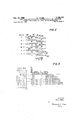
- a data processing machine conventionally comprises a function controlling movable slide member 600 which is movable in the course of the machine operation from a starting position I into a plurality of positions II-VI which are illustrated sequentially from top to bottom of FIG. 2. Each position is assigned to a different signal as indicated next to these positions in FIG. 2.
- Various means are provided in order to stop the slide member 600 in the dilerent desired posi-tions.
- Three stop levers 100, 200 and 300 are arranged to be lifted from their normal positions shown in the uppermost and in the lowermost portions of FIG.
- Each of the stop levers 100, 200 and 300 has a notched opera-tive end which is adapted to engage and to stop the front end of the slide member 600 when the particular stop lever is lifted. It can be recognized easily from FIG. 2 that when the slide member 600 is to be stopped in position II the stop lever 100 is to be lifted. When the slide member 600 is to be stopped in position III the stop lever 200 is to be lifted. When the slide member 600 is to be stopped in position IV none of the stop levers is to be lifted but the slide member 600 is moved downwardly in a conventional manner so that a shoulder 601 thereof abuts against a stop 602 adjustable in conventional manner by the pin carriage of the machine.
- control magnets 1, 2 and 3 are shown and adjacent thereto diagrammatically the respectively associated stop lever 100, 200 and 300.
- the control magnet 1 is assigned to the signal
- control magnet 2 is assigned to the signal
- control magnet 3 is assigned to the signal meaning Total
- the control magnets 1, 2 and 3 are connected in parallel with each other between the lines 52 and 53.
- the line 52 is connected via a normally closed control contact k1 with a line 48 which leads to a terminal 8 Where positive potential U -ifrom a source B is available.
- the line 53 is connected across an electromagnet 4 with a line 49 which leads to a terminal 7 where the negative potential U from the source B is available.
- each of the control magnets 1, 2 and 3 is controllable by a relay contact 101, 201, and 301, respectively, interposed between the respective magnets and the line 53.
- a resistor is connected in parallel with the control magnets 1, 2 and 3 between the lines 52 and 53 and current through this resistor is permitted to flow only when a corresponding relay contact 501 is closed.
- relay coils 10, 20, 30 and 50 respectively, of which coil 10 operates relay contacts 101 and 102, coil 20 operates relay contacts 201 and 202, coil 30 operates relay contacts 301 and 302 and coil 50 operates relay contacts 501 and 502.
- the relay coils 10, 20, 30 and 50 are connected in parallel with the above-mentioned line 49 carrying negative potential.
- the other ends of the coils 10, 20, 30 and 50 are connected with the above-mentioned input terminals K10-46 and 11M-46 as will be described now.
- Relay coil 10 is connected by a line 11 with the input terminal 42 assigned to the signal
- the relay coil 20 is connected via line 21 with input terminal 43 assigned to the signal
- the relay coil 50 is connected via line 51 with the input terminal 44 assigned to the signal nocalculation and also with the terminal 45 assigned to the signal "Subtotal.
- ythe relay coil is connected by line 31 with the input terminal 46 assigned to the signal Total.
- relay contacts 102, 202, 502 and 302 are connected by lines 110, 210, 510 and 310, respectively, with the above-mentioned line 52 carrying positive potential so that these relay contacts serve to hold the respective relay coil in energized condition ⁇ after it has been energized, until the control contact k1 is moved to open condition as will be explained later.
- the terminal is connected directly by the line 48 with terminal 8 so as to carry also the positive potential U -i-.
- the input terminal S1 assigned to an advance signal VS is connected by a line 47 via a normally closed control contact k2 with a further control relay coil V the other end of which is connected to line 49 and thereby with the negative terminal 7. It is evident that if signals are applied in decimal form to the terminals 411-46 the relay coils 10, 20, 30 and 50 will be energized accordingly. However, it is necessary to be able to energize these control relays also by means of input signals furnished for instance from the decorder D to the second set of input terminals @lV-46'. Therefore, the above-mentioned lines 11, 21, 51 and 31 are extended to connect the respective relay coils also with the input terminals 421-46', the extensions starting at the respective junction points 111, 211, 511 and 311.
- FIG. 3 by way of example a portion of a perforated tape T is shown which has perforations or holes arranged in five rows I-V. According to the code used in this case, one hole each in rows lll, IV represents the advance signal VS. One hole each in rows I and V represents the signal J.- as indicated in the first column of the chart in FIG. 3. One hole each in rows I and Il represents the signal One hole each in rows I and IV represents the signal no-calculation.
- a combination of two signals namely of the signal VS and the signal appearing simultaneously as indicated by one hole each in the rows l, Il, lll and lV, represents the instruction Total
- the second column of FIG. 3 indicates the signals available for being introduced preceding the digit signals. If only the advance signal VS alone precedes the digit signals then this advance signal has only the meaning that the next following signals will be digit signals.
- the signal preceding the digit signals is a combination of the advance signal VS and one of the signals representing -lor then this signal constitutes the instruction that the following digit signals are to be processed to form a total or a subtotal, respectively.
- the third column of FlG. 3 indicates the meaning of signals following the digit signals.
- the signal following the digits will constitute either the order to add the digits represented by the just introduced digit signals to any other number or digit stored or recorded in the machine, the signal will constitute the order to subtract the justmentioned digit or digits from a previously stored or recorded digit or number and finally, the signal i# represents the order no-calculation so that the previously introduced digit or digits will not be further processed.
- the signal introduced preceding the digit signals is one of the above-mentioned combination signals then the signal -lappearing after the introduction of the digit signals will indicate that the respective total or subtotal is positive while the appearance of the signal appearing after the digit signals will in this case only indicate that the respective'total or subtotal is negative.
- the input terminal 42 assigned to the signal is connected via line 4S and line l1 with the relay coil ltl assigned to the signal -lwhile the input terminal 43 assigned to the signal is connected via line i9 and line 2l with the relay coil 2t) which is also assigned to the signal
- a train of signals introduced from or delivered by the decoder D comprises an advance signal VS, a digit signal or signals and a following functional instruction signal, e.g. the signal
- the input of the signal VS causes as eX- plained above, energization of the relay coil V and a change of position of the relay contacts v1 and v2.
- the relay coil V is maintained in energized condition by conventional means not shown until the normally closed control contact k2 is moved to. open position.
- the relay coil Sil is energized causing the relay contacts SG1 and 592 to move to closed position whereby a current flow through the electromagnet 4 and through the resistor 5 is caused theresistance of which is approximately equivalent to that of the individual control electromagnets ll, 2 and 3.
- the stop levers Miti, 290 or Stlt are lifted and the slide member dull will be stopped as explained above in its position IV. Under these conditions no calculation will be carried out after the input of the respective digit signals.
- the corresponding command signals will be derived from those hole cornbinations in the tape T ⁇ which represent these orders. These signals will be applied to the input terminals 46 or 45', respectively.
- the signal Subtotal applied to input terminal 45 is transmitted via line 51 to the control elay coil 5t) so that in the same manner as described above for the input signal no-calculation none of the stop levers ltltl, 200 and 300 will be lifted and the slide member l is free to be moved forward until it abuts against the stop 603 and thus assumes the position VI whereby the machine is caused to form a subtotal from the following digit signals.
- This signal is transmitted via line 49, con-r tact v2, contact and line ll, to the control relay coil 1t) with the result that the respectively associated stop lever lltltl is lifted by the control electromagnet 1 into the path of the slide member 604i so that the latter is permitted to move into position II. Consequently, the previously formed total and the now introduced number are subtracted from each other so that the result of this subtraction is zero, provided that the thus processed numbers are identical.
- a plurality of stop means each individually movable between an idle position and an operative position in which a portion thereof projects into the path of said slide member to stop the movement of the latter in respectively different predetermined positions respectively associated with different ones of said second actuation signals; a plurality of control electromagnet means for individually moving upon energizaytion thereof said plurality of stop means, respectively, to the operative position thereof; a plurality of control relay means for selectively causing when energized the energization of said control electromagnet means, respectively; a plurality of input means for receiving each a different one of said second actuation signals and respectively connected with corresponding ones of said plurality of said control relay means, lrespectively, for applying said signals, respectively, to, and for correspondingly energ
- a plurality of stop means each individually movable between an idle position and an operative position in which a portion thereof projects into the path of said slide member to stop movenient of the latter in respectively different predetermined positions respectively associated with different ⁇ ones of said second actuation signals; a plurality of control electromagnet means for individually moving upon energiza- :tion thereof said plurality of stop means, respectively, to lthe operative position thereof; a plurality of control relay means for selectively causing when energized the energization of said control electromagnet means, respectively; a plurality of input means for receiving each a different one of said second actuation signals and respectively connected wi-th corresponding ones of said plurality of said control relay means, respectively, for applying said signals, respectively, to, and for
- a data processing machine operable by first electrical actuation signals representing digits and by second actuation signals representing, respectively, different symbols or functional instructions, and having a movable slide member controlling the processing of said second actuation signals, in combination, a rst, a second and a third stop means, each Iindividually movable between an idle position and an operative position in which a portion thereof projects into the path of said slide member to stop the movement of the latter in respectively different predetermined positions respectively associated with those of said second actuation signals which represent the instructions plus, minus and TotaL respectively; a first, a second and a third control electromagnet means for individually moving upon energization thereof said first, second and third stop means, respectively, to the operative position thereof; a first, a second and a third control relay means for selectively causing when energized the energization of said first, second and third contro-l electromagnet means, respectively; a first, a second and a third input means for receiving each
- a first, a second and a third stop means each individually movable between an idle position and an operative position in which a portion thereof projects into the path of said slide member to stop movement of the latter in respectively different predetermined positions respectively associated with those of said second actuation signals which represent the instructions plus, minus and Total, respectively; a first, a second and a third control electromagnet means for individually moving upon energization thereof said first, second and third stop means, respectively, to the operative position thereof; a resistor means, connected in parallel with all of said control electromagnet means, a
- first, a second and a third control relay means for selectively causing when energized the energization of said first, second and third control electromagnet means,l respectively, and a fourth control relay means for causing when energized a flow of current through said resistor means; a first, a second and a third input means for receiving each a different one of said second actuation signals which represent the instructions plus, minus and Total, respectively, and respectively connected with corresponding ones of said first, second and third control relay means, respectively, for applying said signals, respectively, to, and for correspondingly energizing, the latter, and fourth input means for receiving those of said signals representing the instructions no calculation and Subtotal and connected with said fourth control relay means for applying said last mentioned signals to, and for correspondingly energizing, said fourth control relay means; a special separate relay means responsive to an advance signal constituting a selected one of said' second actuation signals and including two changeover contact means operable by energization of said separate relay means and arranged between said first
- each of said first, second, third and fourth control relay means is provided with holding means for keeping an energized one of said control relay means in energized condition, and wherein a normally closed control contact means is connected in series with all of said holding means and with said control electromagnet means and with said resistor means, said normally closed control Contact means being adapted to be moved to open position at the endof a predetermined portion of the operational cycle of the machine so as to interrupt thereupon the iiow of current through all of said holding means, control relay means, control magnet means and said resistor means.
- a single movable slide bar means controlling the processing of said second actuation signals; a plurality of stop means all of which cooperate with said single movable slide bar means, each of said stop means being individually movable between an idle position and an operative position in which a portion thereof projects into the path of said slide bar means to stop the movement of the latter in respectively different predetermined positions respectively associated with different ones of said second actuation signals; a plurality of control eelctrornagnet means for individually moving upon energization thereof said plurality of stop means, respectively, to the operative position thereof; a plurality of control relay means for selectively causing when energized the energization of said control electromagnet means, respectively; a plurality of input means for receiving each a different one of said second actuation signals and respectively connected with corresponding ones of said plurality of said control relay means,
Landscapes
- Engineering & Computer Science (AREA)
- Theoretical Computer Science (AREA)
- Human Computer Interaction (AREA)
- Physics & Mathematics (AREA)
- General Engineering & Computer Science (AREA)
- General Physics & Mathematics (AREA)
- Keying Circuit Devices (AREA)
- Toys (AREA)
- Chairs For Special Purposes, Such As Reclining Chairs (AREA)
- Electromagnets (AREA)
- Relay Circuits (AREA)
Applications Claiming Priority (1)
| Application Number | Priority Date | Filing Date | Title |
|---|---|---|---|
| DEO8108A DE1292414B (de) | 1961-06-19 | 1961-06-19 | Eingabevorrichtung an datenverarbeitenden Maschinen |
Publications (1)
| Publication Number | Publication Date |
|---|---|
| US3169702A true US3169702A (en) | 1965-02-16 |
Family
ID=7351323
Family Applications (1)
| Application Number | Title | Priority Date | Filing Date |
|---|---|---|---|
| US203624A Expired - Lifetime US3169702A (en) | 1961-06-19 | 1962-06-19 | Input means for introducing function signals and functional instruction signals to a data processing machine |
Country Status (5)
| Country | Link |
|---|---|
| US (1) | US3169702A (de) |
| CH (1) | CH386745A (de) |
| DE (1) | DE1292414B (de) |
| GB (1) | GB1013302A (de) |
| SE (1) | SE300720B (de) |
Citations (3)
| Publication number | Priority date | Publication date | Assignee | Title |
|---|---|---|---|---|
| US1895095A (en) * | 1930-12-15 | 1933-01-24 | Int Communications Lab Inc | Cable code printer |
| US2405297A (en) * | 1945-03-17 | 1946-08-06 | Ibm | Telegraphic printing apparatus |
| US3063625A (en) * | 1962-11-13 | Data processing systems |
Family Cites Families (1)
| Publication number | Priority date | Publication date | Assignee | Title |
|---|---|---|---|---|
| DE1052721B (de) * | 1957-04-13 | 1959-03-12 | Deutsche Bundesbahn | Elektrische Werteingabevorrichtung fuer Rechenmaschinen |
-
1961
- 1961-06-19 DE DEO8108A patent/DE1292414B/de active Pending
-
1962
- 1962-06-12 CH CH699762A patent/CH386745A/de unknown
- 1962-06-19 SE SE6854/62A patent/SE300720B/xx unknown
- 1962-06-19 US US203624A patent/US3169702A/en not_active Expired - Lifetime
- 1962-06-19 GB GB23497/62A patent/GB1013302A/en not_active Expired
Patent Citations (3)
| Publication number | Priority date | Publication date | Assignee | Title |
|---|---|---|---|---|
| US3063625A (en) * | 1962-11-13 | Data processing systems | ||
| US1895095A (en) * | 1930-12-15 | 1933-01-24 | Int Communications Lab Inc | Cable code printer |
| US2405297A (en) * | 1945-03-17 | 1946-08-06 | Ibm | Telegraphic printing apparatus |
Also Published As
| Publication number | Publication date |
|---|---|
| DE1292414B (de) | 1969-04-10 |
| SE300720B (de) | 1968-05-06 |
| CH386745A (de) | 1965-01-15 |
| GB1013302A (en) | 1965-12-15 |
Similar Documents
| Publication | Publication Date | Title |
|---|---|---|
| GB791608A (en) | Improvements in or relating to error checking system | |
| US3169702A (en) | Input means for introducing function signals and functional instruction signals to a data processing machine | |
| GB853691A (en) | A method and means for the automatic repetition of signal transmissions | |
| GB586596A (en) | Improvements in or relating to record card controlled accounting machines | |
| US2873837A (en) | Automatic code translating systems | |
| US2933563A (en) | Signal translating circuit | |
| US3012723A (en) | Electronic computer system | |
| GB904607A (en) | Programme controlled electronic data processing system in particular computing, booking and/or sorting system | |
| US3634950A (en) | Electrical arrangement for use in teaching machine | |
| US1876293A (en) | Electric calculating machine | |
| US2775299A (en) | Record card reproducing punching machine with program control | |
| US3137840A (en) | Output arrangement for data processing machines | |
| US3018042A (en) | Data input system | |
| US3072333A (en) | Remote controlled adder/subtracter using coded frequency inputs | |
| US3072331A (en) | Apparatus for processing decimal numbers | |
| US3158429A (en) | System for recording registered data | |
| US2972089A (en) | Programming circuits | |
| US3055587A (en) | Arithmetic system | |
| US3077829A (en) | Rotary selectively printing duplicator | |
| US2301823A (en) | Impulse mechanism | |
| US2327465A (en) | Pulse regenerator | |
| DE2511791C3 (de) | Elektronisch gesteuerte Fernsprechnebenstellenanlage | |
| US2039806A (en) | Punching machine | |
| US2340851A (en) | Multiplying machine | |
| US2036683A (en) | Tabulating machine |