US3213615A - Hydraulically actuated reciprocable tools - Google Patents
Hydraulically actuated reciprocable tools Download PDFInfo
- Publication number
- US3213615A US3213615A US123145A US12314561A US3213615A US 3213615 A US3213615 A US 3213615A US 123145 A US123145 A US 123145A US 12314561 A US12314561 A US 12314561A US 3213615 A US3213615 A US 3213615A
- Authority
- US
- United States
- Prior art keywords
- piston
- bore
- casing
- pressure
- fluid
- Prior art date
- Legal status (The legal status is an assumption and is not a legal conclusion. Google has not performed a legal analysis and makes no representation as to the accuracy of the status listed.)
- Expired - Lifetime
Links
- 239000012530 fluid Substances 0.000 claims description 128
- 238000004891 communication Methods 0.000 claims description 20
- 230000006835 compression Effects 0.000 claims description 8
- 238000007906 compression Methods 0.000 claims description 8
- 238000007789 sealing Methods 0.000 description 10
- 230000002093 peripheral effect Effects 0.000 description 6
- 229910000831 Steel Inorganic materials 0.000 description 5
- 239000010959 steel Substances 0.000 description 5
- 230000001133 acceleration Effects 0.000 description 3
- 239000002131 composite material Substances 0.000 description 3
- 238000013016 damping Methods 0.000 description 3
- 230000000694 effects Effects 0.000 description 3
- 238000011010 flushing procedure Methods 0.000 description 3
- 239000007788 liquid Substances 0.000 description 3
- 230000015572 biosynthetic process Effects 0.000 description 2
- 238000010276 construction Methods 0.000 description 2
- 230000010349 pulsation Effects 0.000 description 2
- 101150101537 Olah gene Proteins 0.000 description 1
- 208000036366 Sensation of pressure Diseases 0.000 description 1
- 230000008878 coupling Effects 0.000 description 1
- 238000010168 coupling process Methods 0.000 description 1
- 238000005859 coupling reaction Methods 0.000 description 1
- 230000003247 decreasing effect Effects 0.000 description 1
- 238000006073 displacement reaction Methods 0.000 description 1
- 238000012986 modification Methods 0.000 description 1
- 230000004048 modification Effects 0.000 description 1
- 230000000149 penetrating effect Effects 0.000 description 1
- 238000005086 pumping Methods 0.000 description 1
- 230000001105 regulatory effect Effects 0.000 description 1
- 230000000284 resting effect Effects 0.000 description 1
- 230000035939 shock Effects 0.000 description 1
- 230000001360 synchronised effect Effects 0.000 description 1
- 239000002699 waste material Substances 0.000 description 1
- XLYOFNOQVPJJNP-UHFFFAOYSA-N water Substances O XLYOFNOQVPJJNP-UHFFFAOYSA-N 0.000 description 1
Images


Classifications
-
- F—MECHANICAL ENGINEERING; LIGHTING; HEATING; WEAPONS; BLASTING
- F01—MACHINES OR ENGINES IN GENERAL; ENGINE PLANTS IN GENERAL; STEAM ENGINES
- F01B—MACHINES OR ENGINES, IN GENERAL OR OF POSITIVE-DISPLACEMENT TYPE, e.g. STEAM ENGINES
- F01B23/00—Adaptations of machines or engines for special use; Combinations of engines with devices driven thereby
- F01B23/06—Adaptations for driving, or combinations with, hand-held tools or the like
-
- B—PERFORMING OPERATIONS; TRANSPORTING
- B25—HAND TOOLS; PORTABLE POWER-DRIVEN TOOLS; MANIPULATORS
- B25D—PERCUSSIVE TOOLS
- B25D9/00—Portable percussive tools with fluid-pressure drive, i.e. driven directly by fluids, e.g. having several percussive tool bits operated simultaneously
- B25D9/06—Means for driving the impulse member
- B25D9/12—Means for driving the impulse member comprising a built-in liquid motor, i.e. the tool being driven by hydraulic pressure
-
- B—PERFORMING OPERATIONS; TRANSPORTING
- B25—HAND TOOLS; PORTABLE POWER-DRIVEN TOOLS; MANIPULATORS
- B25D—PERCUSSIVE TOOLS
- B25D9/00—Portable percussive tools with fluid-pressure drive, i.e. driven directly by fluids, e.g. having several percussive tool bits operated simultaneously
- B25D9/14—Control devices for the reciprocating piston
- B25D9/16—Valve arrangements therefor
- B25D9/22—Valve arrangements therefor involving a rotary-type slide valve
Definitions
- the primary object of the invention is to provide an improved hydraulically actuated motor which is simple and durable in construction and has a highly efficient pressure fluid distributing system having small hydraulic losses owing to flow resistance.
- Another object of the invention is to provide an improved hydraulically actuated reciprocable motor, wherein the reciprocating parts are efliciently sealed so as to eliminate leakage and waste of liquid.
- Another object of the invention is to provide an improved hydraulically actuated reciprocable impact tool having a single pressure accumulator inserted for damping pressure fluctuations in the supply as Well as in the return line of the tool.
- a more specific object of the invention is to provide a hydraulically actuated reciprocable impact tool having a pressure accumulator incorporating spring means in a cylinder acting on a piston for damping pressure fluctuations in said supply and return lines.
- Another object of the invention is to provide a hydraulically actuated reciprocable impact motor having damper chambers at the opposed ends of the bore in which the piston is reciprocable, said damper chambers preventing the piston from striking against the motor casing and eliminating the need for special fluid compression means for damping purposes outside of the piston bore on the elongated ends of the piston.
- An additional object of the invention is to provide a hydraulically actuated reciprocable impact motor having a pair of totally balanced valves for admitting high pressure fluid to the piston faces and connecting said piston faces to a low pressure fluid outlet, respectively, having a single hydraulic motor drive-coupled to and synchronizing the movement of said valves.
- Another object of the invention is to provide a gear motor or pump for operating said valves or for other purposes having hydraulically balanced intermeshing gears in order to reduce the friction at the high pressure fluid inlet portion of the gear motor or pump.
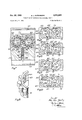
- FIG. 1 is a longitudinal sectional view of a hydraulically actuated reciprocable impact tool embodying the invention
- FIG. 2 is a fragmental enlarged View of the cylinder section in FIG. 1
- FIG. 3 is a fragmental enlarged view of the accumulator section in FIG. 1
- FIG. 4 is an enlarged sectional view of the valve casing on line 44 in FIG. 5
- FIG. 5 is a sectional view on line 55 in FIG. 4
- FIG. 6 is a sectional view on line 6-6 in FIG. 4
- FIG. 7 is a transverse sectional view through the gear motor for ro- 3,213,615 Patented Oct.
- FIG. 8 is a fragmental perspective view of one of the gear Wheels of FIG. 7; and FIGS. 9-12 are fragmental sectional views through the valve system in four different valve positions during a full operating cycle of the impact tool.
- the tool shown in FIG. 1 is provided with a composite casing which may be portable or may for power feeding purposes be mounted on a suitable feeding device.
- the composite casing incorporates a central cylinder section 11 having centrally therethrough a cylinder bore 12 and carrying in coaxial arrangement a rear section 13 and a front member 14, the latter having a forwardly directed chuck section 15.
- the parts 11, 13, 14 and 15 of the composite casing are as conventionally firmly clamped together by means of bolts, not shown.
- a piston head 16 having a sliding fit in the cylinder bore 12 and being provided with forwardly and rearwardly extending elongated ends or stems 17 and 18.
- the rearwardly extending elongated end 18 has preferably a smaller diameter than the opposed elongated end 17, thereby providing a somewhat greater surface on the rear face of the piston head '16 to be actuated upon by incompressible fluid under pressure than provided on theforward face of the piston head.
- the piston head 16 has a maximum diameter of 1.3 times the diameter of the elongated end 18.
- annular end members or sealing blocks 19 and 20 of steel provided with outer ring seals 21 on the forward and rearward portion of the outer mantle of the respective sealing block, FIG. 2.
- the blocks 19, 20 are held with some small play in enlarged bores 22 in the cylinder section 11 with the ring seals 21 tightening thereagainst.
- each block 19, 20 has a tight sliding fit around the pertaining elongated end 17, 18 of the piston head 16.
- the damper chambers may have a diameter slightly greater than the diameter of the piston head 16 or bore 12, for example 0.2 mm.
- a rotary chuck 26 which may be rotated by a motor preferably a conventional gear type hydraulic motor indicated at 27, which may be of well known construction and consequently is not shown in detail.
- the rotary chuck 26 cooperates with and rotates the shank of the drill steel 28 which is provided with an axial passage 29 therethrough for the flushing fluid.
- a liquid conducting tube 30 ex tends from the rear section 13 through an axial bore 39 through the piston head and its elongated ends and penetrates at its tip into the passage 29 of the hollow drill steel 28.
- a hose terminal 31 for the connection of a water hose is provided at the rear portion of the section 13 and is connected thereto by means of a cylindrical threaded plug 321. From the hose terminal 31 the flushing fluid is directed into the flushing tube 30 and passes therefrom into the hollow drill steel 28.
- a valve housing 33 On the cylinder section 11 there is a radially protruding portion with an open ended cylindrical aperture 32 into which there is inserted a valve housing 33.
- the housing 33 is kept in place by means of a sealing abutment for the aperture 32 on an accumulator section 34.
- the section 34 is connected to the radially protruding portion of the cylinder section 11 by means of bolts, not shown.
- a high-pressure fluid connection 35 and a low-pressure fluid connection 36 are connected to the accumulator section 34 and lead to a bore 38 provided therein.
- a piston 37 is reciprocably arranged in the bore 38 and its opposed faces are acted upon by high-pressure fluid and low-pressure fluid, respectively.
- annular elastically flexing spring discs 40 in bellows arrangement between an end closure 39 for the bore 38 and the low-pressure face of the piston 37.
- a flexible springy stop ring 41 FIG. 3, is inserted through a tangential perforation into aligned annular grooves formed on the peripheries of the end member 39 and bore 38 in order to keep the end closure 39 in place in the bore 38.
- the precompression and the elastic properties of the spring disc arrangement may be chosen to give a constant spring force resisting compression of the spring discs 40.
- the discs are grouped around a hollow axially extended portion 42 of the piston 37, the end of the portion remote from the piston 37 being slidably supported by a bearing 43 on the closure member 39 also acting as an abutment for the discs. Suitable perforations are provided in the mantle of the extended portion 42 as well as in the base of the bearing 43 in order to secure free circulation of pressure fluid.
- an extension 44 cooperating with and resting against the housing of the accumulator section 34 when the pressures on opposed sides of the piston 37 are equalized.
- the aggregate of spring discs 40 is divided into two groups which are separated by a cylindrical spacing member 45 adjacent the connection 36 in order to provide for free pressure fluid flow transversely through the accumulator section 34.
- a highpressure passage 46 and a low-pressure return passage 47 are provided between the bore 38 and the valve housing 33 and are connected to the bore at opposed sides of the accumulator piston 37.
- the high-pressure passage 46 is in constant communication with the interior 48 of a rotary automatic control valve 48 extending axially of the valve housing 33 while the interior 49 of a similar control valve 49 arranged in spaced-apart parallel relationship with the valve 48 is in constant communication with the low-pressure passage 47.
- the control valves 48 and 49 are formed hollow and cylindrical and are provided with diametrically opposed valve slits 50.
- Two intermeshing gear wheels 51, 52 of a gear motor are made integral with the control valves 48, 49.
- Each gear wheel 51, 52 is supported by and fits snugly into a cylindrical aperture 53 in the control valve housing 33 and is pivotally supported by a cylindrical hollow journal 54 extending in concentric relation with respect to the cylindrical apertures 53.
- the hollow journals 54 form intermediate passages between the interior of the control valves 48, 49 and the inlet and outlet passages 46, 47, respectively.
- Radially extending flanges 55 on the journals 54 form closures for the apertures 53 and are clamped in place between the accumulator section 34 and the valve casing 33. Between each flange 55 and the bottom of the apertures 53 there is formed a working space for the two inter.- meshing gear wheels 51, 52 of the gear motor.
- a passage 56 leads from the high-pressure fluid passage 46 to the high-pressure fluid side of the gear motor, while its lowpressure fluid side is vented to the outlet passage 47 by means of a passage 57.
- the pres-sure fluid flow passing the passage 56 for driving the gear motor is coupled in parallel with respect to the main flow for driving the piston 16.
- Slidably inserted into the passage 56 is a piston shaped valve 58 having a number of axial perforations 59 for throttling the flow therethrough and a forwardly protruding tip 60.
- the tip 60 coacts with a restricted portion 62 of the passage 56 and is prevented from closing said restricted portion 62 by means of a helical spring 61 which is supported between the valve 58 and a shoulder adjacent the portion 62.
- valve housing 33 Opening up into the direction of the cylinder section 11 there are arranged in the valve housing 33 two parallel axially extending chambers 24 and 25 the chamber 24 communicating with the inlet 24 of the cylinder bore 12 while the chamber 25 is in communication with the corresponding inlet 25.
- the rotating control valves 48 and 49 are in their turn rotatably nested in valve bores 65 and 66 arranged at the opposite side of the valve casing 33 with respect to the chambers 24 and 25
- passages for balancing of the pressures :acting upon these valves in every direction and under all conditions of operation To this end there are provided pairs of diametrically opposed and interconnected distributing grooves in the valve bores 65 and 66 by which equalization of pressures during the operation of the valves is etfected. Adjacent the control valve 48, the interior 48.
- a second pair of opposed distributing grooves 69 is provided in the valve bore 65 for feeding the chamber 24 and the inlet 24 with high-pressure fluid, there being likewise provided -a peripheral groove 70, FIG. 6 in the valve housing 33 for equalization of the pressures acting in the grooves 69 of the valve 48.
- valve bore 66 of the valve 49 In the valve bore 66 of the valve 49, the interior 49 of which is in permanent communication with the low-pressure exhaust passage 47, there are in full analogy arranged the opposed distributing grooves 71 for connecting the chamber 24 and consequently the inlet 24 to the exhaust passage 47, pressure equalization between the grooves 71 being performed by means of a peripheral groove 72, FIG. 5, while opposed peripheral additional grooves 73 are arranged for connecting the chamber 25 i.e., the inlet 25 to the passage 47.
- the pressures in the grooves 73 are equalized by means of a peripheral groove 74, FIG. 6.
- perforations 75 For balancing the ends of the valves 48, 49 adjacent the gears 51, 52 there are arranged perforations 75 through the journals 54, FIG. 4.
- the tool Prior to operation the tool has to be connected by means of the inlet and exhaust connections 35, 36 as well as by the connections leading to the drill chuck motor 27, to a suitable hydraulic supply incorporating "a continuously functioning hydraulic pressure producer or pump delivering high-pressure fluid at a substantially constant pressure.
- a suitable hydraulic supply incorporating "a continuously functioning hydraulic pressure producer or pump delivering high-pressure fluid at a substantially constant pressure.
- Such hydraulic pressure producer together with its auxiliary equipment such as a suitable reservoir, liquid filters, pressure regulating valves and their arrangement are well known in the art and will not be described here.
- the conventional throttle valve connected in parallel between the inlet connection and the exhaust connection at a suitable place and providing a by-pass for returning the continuous fluid flow to the supply reservoir in the non-operative position of the throttle valve.
- the rear face of the piston head is brought into communication with the exhaust passage 47 through the inlet 25, the chamber 25 the balancing groove 74, the axial grooves 73, the valve slits 50 and the interior 49 of the valve 49.
- the low-pressure fluid passes transversely through the bore 38 of the accumulator section 34 past the distance ring 45 to the lowpressure fluid connection 36.
- the pressure fluid acting on the forward face of the piston head 16 displaces the piston rearwardly and performs the return stroke.
- the valves 48, 49 next the position shown in FIG. 10 is passed.
- the accumulator takes up the pressure fluid returning from the cylinder bore 12 through the passage 46 as well as streaming from the pressure producer through the inlet connection 35. Subsequently the piston 1648 is finally stopped by the pressure fluid acting on the rear face of the piston head 16, and in the valve position shown in FIG. 12 and there begins an acceleration of the piston in forward direction in order to perform 'an impact against the drill shank 28.
- valve 48 pressure fluid from the inlet connection 35 as well as from the high-pressure side of the filled accumulator may now pass through the valve 48 in order to be directed via the grooves 67 to the inlet 25 and the rear face of the piston head 16, simultaneously with the forward face of the piston being connected to the exhaust connection 36 over the inlet 24, the valve 49, and the low pressure side of the accumulator.
- the valves 48, 49 are in the position shown in FIG. 12.
- the piston is now practically stationary as it has given up its energy of motion to the drill shank and consequently there is performed no subsequent pumping action back through the valve 48 to the accumulator.
- the valves 48 and 49 turn into a position corresponding to the position shown in FIG. 9, which means the beginning of a new impact cycle.
- the pressure accumulaton during operation of the tool absorbs high pressure peaks and inertial fluid shocks resulting from the operation of the valves 48, 49 and the piston 16-18. Likewise it takes up and stores pressure fluid at instants when such pressure fluid may not pass to the faces of the moving piston while it delivers pressure fluid to the cylinder bore at instants when the pressure producer fails to fully cover the fluid quantity needed.
- the energy originally fed through the control valve system for performing the return stroke has to be exchanged or pumped through the valve casing in the form of pressure fluid not less than three times, that is to say firstly from the high pressure side to the front face of the piston head during the return acceleration, subsequently from the rear face to the pressure accumulator during retardation of the return stroke and finally back again from the pressure accumulator to the rear face of the piston head during acceleration of the piston in order to perform an impact. Consequently, an important feature for the eflicient operation of the impact tool described is the provision for small flow resistances in the control valve system. As readily seen the fluid passages in the valve system are formed with wide cross-sectional areas and as short as possible permitting the pressure fluid to flow with a minimum of disturbances.
- the pressure peaks generated are utilized for loading up the pressure accumulator which subsequently returns its stored energy to the piston.
- the pressure accumulator greatly moderates the peak pressures acting at the high pressure fluid inlet 46, so that no excessive pulsations may be reflected out through the inlet and outlet connections 35, 36. Owing to the coupling of the pressure accumulator in parallel with the valve system excessive pressure pulsations in the exhaust passage 47 may also be equalized by the accumulator.
- the piston head 16 may be thrown past its usual reversal and stopping points in which case the damper Chambers 23 will prevent the piston from hitting against the ends of the tool casing or the blocks 19 and 20.
- the pressure generated therein will act on the outer mantle of the blocks owing to the play between the blocks 19, 20 and the cylinder section 11 and will compress the blocks inwards thereby increasing the sealing action of the steel blocks 19 and 20 and counteracting the high-pressure tending to give rise to leakage.
- the high-pressure generated in the damper chambers is confined to the chambers and unable to act on the control valve system.
- a casing having a bore, a piston head reciprocable within said bore and having a sliding fit therein, said piston head having opposite faces alternately exposable to incompressible fluid under pressure, opposed elongated free ends on said piston head, said ends being axially unaffected by fluid under compression, the piston head having maximally a diameter 1.3 times the minimum diameter of said elongated ends, an end member in said casing at one end of said bore providing a seal between said casing and one of said elongated ends, hydraulic damper means between said bore and said end member for absorbing the energy of said piston at the end of its stroke in the direction of said end member, a highpressure fluid inlet and low-pressure fluid outlet associated with said casing, a first totally balanced valve associated with said casing in proximity to said bore, said first valve in constant communication with said inlet and being movable to alternately admit said high-pressure fluid to said opposed piston faces, a second totally balanced valve associated with said casing in proximity to
- a casing having a bore, a piston reciprocable within said bore and having opposed faces alternately exposable to incompressible fluid under pressure, an elongated end on said piston, an end member in said casing at one end of said bore providing a seal between said casing and said elongated end, a passage adjacent the end of said bore and axially spaced therein from said end member for introducing and withdrawing said fluid into and from said bore, distributing means associated with said casing to alternately admit and withdraw said fluid through said passage for reciprocating said piston, and an annular damper chamber in said bore and axially between said passage and said end member, said damper chamber having a diameter slightly greater than said bore for absorbing the energy of said piston at the end of its stroke in the direction of said end member.
- a casing having a bore, a piston reciprocable within said bore and having opposed faces alternately exposable to incompressible fluid under pressure, an elongated end on said piston, an annular sealing block in said casing at one end of said bore providing a seal between said casing and said elongated end, distributing means associated with said casing to alternately admit said fluid to said opposite piston faces for reciprocating said piston, hydraulic damper means between said bore and said block for absorbing the energy of said piston at the end of its stroke in the direction of said black, and a connection between said damper means and the outside of said block providing access for said fluid to compress said block inwardly in radial direction.
- a casing having a bore, a piston reciprocable within said bore and having opposed faces alternately exposable to incompressible fluid under pressure, an elongated end on said piston, an annular sealing block in said casing at one end of said bore providing a seal etween said casing and said elongated end, distributing means associated with said casing to alternately admit said fluid to said opposite piston faces for reciprocating said piston, an annular damper chamber having a diam eter slightly greater than said bore between said bore and said block for absorbing the energy of said piston at the end of its stroke in the direction of said block, and a connection between said damper chamber and the outside of said block providing access for said fluid to compress said block inwardly in radial direction.
- a casing having a bore, a piston reciprocable within said bore and having opposed faces alternately exposable to incompressible fluid under pressure, opposed elongated ends on said piston, annular sealing blocks in said casing at the opposite ends of said bore providing a seal between said casing and said elongated ends, distributing means associated with said casing to alternately admit said fluid to said opposite piston faces for reciprocating said piston, an annular damper chamber having a diameter slightly greater than said bore between said bore and each block for absorbing the energy of said piston at the end of its strokes, and a connection between said damper chambers and the outside of said blocks providing access for said fluid to compress said block inwardly in radial direction.
- a casing having a bore, a piston head reciprocable within said bore and having a sliding fit therein, the piston head having opposite faces alternately exposable to incompressible fluid under pressure, opposed elongated constant diameter stems on said piston head, said stems extending axially throughout said bore and being axially unaffected by fluid under compression, the piston head having maximally a diameter 1.3 times the minimum diameter of said elongated stems of said piston, annular sealing means in said casing at the opposite ends of said bore providing a seal between said casing and said elongated stems, and distributing means associated with said casing to alternately admit said fluid to said opposed piston head faces for reciprocating said piston, said piston being substantially freely sliding in said bore and said stems being free of mechanical connections with other parts.
- a hydraulically actuated reciprocable impact tool comprising in combination, a casing having a bore, a piston reciprocable within said bore and having opposed faces alternately exposable to incompressible fluid under high pressure, a high-pressure fluid inlet and low-pressure fluid outlet associated with said casing, a first to tally balanced valve associated with said casing in proximity to said bore, said first valve in constant communication with said inlet and being movable to alternately admit said high-pressure fluid to said opposed piston faces, a second totally balanced valve associated with said casing in proximity to said bore, said second valve in constant communication with said outlet and being movable to alternately connect said opposed piston faces to said low-pressure fluid outlet, and a single hydraulic motor associated with said casing, said motor drive-coupled to and synchronizing the movement of said valves.
- each valve incorporates a central cavity, said cavity being in constant communication with said inlet and outlet, respectively.
- a gear motor comprising a casing, cylindrical journals in said casing, two intermeshing oppositely rotating gears journalled in said journals in said casing and fitting snugly therein, a high-pressure fluid inlet and a low-pressure fluid outlet at opposite sides of the intermeshing portion of said gears, said journals being concentric with said gears, and means including radial perforations through said gears and connecting said fluid inlet with said journals for hydraulically balancing said gears by leading high-pressure fluid from said fluid inlet to said journals.
- a gear motor as recited in claim 11 in which said gears are provided with pressure fluid cushion-forming reciesses adjacent said perforations and facing said journa s.
- a casing having a bore, a piston reciprocable within said bore, a piston head on said piston having a sliding fit in said bore, said piston head having opposed faces alternately exposable to incompressible fluid under pressure, an elongated end on said piston, an end member in said casing at one end of said bore providing a seal between said casing and said elongated end, distributing means associated with said casing to alternately admit said fluid to said opposite piston faces for reciprocating said piston, passages at the opposed ends of said bore for the admission thereto and emptying therefrom of said fluid, annular damper chambers having a diameter slightly greater than said bore at the opposed ends of said bore and axially beyond said passages for absorbing .the energy of said piston at the ends of each stroke in the direction of said damper chambers, and annular circumferential grooves adjacent said damper chambers and in flow communication with said passages for receiving said fluid from said chambers as said piston head moves therein.
- a casing having a bore, a piston reciprocable within said bore, passages in said casing for conducting incompressible fluid under pressure to said bore for reciprocating said piston, an elongated end on said piston, an end member in said casing at one end of said bore providing a seal between said casing and said elongated end, distributing means associated with said casing to admit said fluid to said passages for reciprocating said piston, a cylindrical enlargement on said piston forming a surface disposed transversely to the longitudinal axis of said piston, an annular damper chamber adjacent said end member, said damper chamber having a diameter slightly greater than said enlargement for receiving said enlargement with the formation of a narrow annular opening therearound thereby to absorb the energy of said piston at the end of its stroke in the direction of said end member, and an annular circumferential groove in said bore axially spaced from said end member and in flow communication with said passage adjacent thereto for receiving fluid from said annular opening as said en
- a casing having a bore, a piston reciprocable within said bore, passages in said casing for conducting incompressible fluid under pressure to the opposed ends of said bore for reciprocating said piston, an elongated end on said piston, an end member in said casing at one end of said bore providing a seal between said casing and said elongated end, distributing means associated with said casing to, admit said fluid to said passages for reciprocating said piston, a piston head on said piston forming opposed faces disposed transversely to the longi- .tudinal axis of said piston, annular damper chambers at the opposed ends of said bore axially beyond said passages, said damper chambers having a diameter slightly greater than said piston head for receiving said head with the formation of a narrow annular opening therearound thereby to absorb the energy of said "piston at the end of its stroke in the direction of said damper chambers, and annular circumferential grooves in said bore adjacent said chambers and in flow communication
- a casing having a bore, a hammer piston reciprocable within said bore and having opposed faces alternately exposable .to incompressible fluid under high pressure, a high pressure fluid inlet and a low pressure fluid outlet in said casing, distributing valve means rotatably disposed adjacent said casing in communication with said inlet and outlet for continuously rotating and alternately admitting said high pressure fluid to said opposed piston faces and alternately connecting said opposed piston faces to said low pressure fluid outlet, a cylinder immediately adjacent and between said inlet and said outlet, an accumulator piston reciprocable within said cylinder and having one side fully exposed to high pressure fluid and the other side fully exposed to low pressure fluid, and annular elastically flexing spring discs in bellows arrangement at the opposite side of said accumulator piston in said cylinder for balancing said accumulator piston against the pressure of the high pressure fluid.
Landscapes
- Engineering & Computer Science (AREA)
- Mechanical Engineering (AREA)
- Physics & Mathematics (AREA)
- Fluid Mechanics (AREA)
- General Engineering & Computer Science (AREA)
- Earth Drilling (AREA)
- Hydraulic Motors (AREA)
Priority Applications (5)
| Application Number | Priority Date | Filing Date | Title |
|---|---|---|---|
| US123145A US3213615A (en) | 1961-07-11 | 1961-07-11 | Hydraulically actuated reciprocable tools |
| GB25021/62A GB945288A (en) | 1961-07-11 | 1962-06-29 | Improvements in hydraulically actuated reciprocable tools |
| CH836462A CH417501A (de) | 1961-07-11 | 1962-07-11 | Hydraulisch betätigtes Gerät mit hin- und herbeweglichem Arbeitskolben |
| CH836662A CH406096A (de) | 1961-07-11 | 1962-07-11 | Hydraulisch betätigtes Schlagwerkzeug |
| CH836562A CH420014A (de) | 1961-07-11 | 1962-07-11 | Hydraulisch betätigtes Gerät mit hin- und herbewegbarem Arbeitskolben |
Applications Claiming Priority (1)
| Application Number | Priority Date | Filing Date | Title |
|---|---|---|---|
| US123145A US3213615A (en) | 1961-07-11 | 1961-07-11 | Hydraulically actuated reciprocable tools |
Publications (1)
| Publication Number | Publication Date |
|---|---|
| US3213615A true US3213615A (en) | 1965-10-26 |
Family
ID=22406961
Family Applications (1)
| Application Number | Title | Priority Date | Filing Date |
|---|---|---|---|
| US123145A Expired - Lifetime US3213615A (en) | 1961-07-11 | 1961-07-11 | Hydraulically actuated reciprocable tools |
Country Status (3)
| Country | Link |
|---|---|
| US (1) | US3213615A (de) |
| CH (3) | CH417501A (de) |
| GB (1) | GB945288A (de) |
Cited By (15)
| Publication number | Priority date | Publication date | Assignee | Title |
|---|---|---|---|---|
| US3371726A (en) * | 1965-05-24 | 1968-03-05 | Gen Dynamics Corp | Acoustic apparatus |
| US3404603A (en) * | 1965-04-23 | 1968-10-08 | Vickers Ltd | Hydraulically operated tools |
| US3470970A (en) * | 1967-11-24 | 1969-10-07 | Canada Iron Foundry Ltd | Hydraulic rock drill |
| US3695366A (en) * | 1970-11-09 | 1972-10-03 | Worthington Corp | Hydraulic hammer with back pressure isolation |
| US3780621A (en) * | 1971-06-07 | 1973-12-25 | Atlas Copco Ab | Hydraulic fluid actuated percussion tool |
| DE2335731A1 (de) * | 1972-07-14 | 1974-01-31 | Komatsu Mfg Co Ltd | Gesteins- oder schlagbohrvorrichtung |
| US4181183A (en) * | 1978-01-05 | 1980-01-01 | Nippon Pneumatic Manufacturing Co., Ltd. | Impact tool |
| US4497467A (en) * | 1982-09-15 | 1985-02-05 | Dewald Carl O | Plug valve with hydraulically actuated seals |
| US4598895A (en) * | 1984-08-31 | 1986-07-08 | Precision Technologies | Plug valve with hydraulically actuated seals |
| WO1994018488A1 (en) * | 1993-02-09 | 1994-08-18 | Hydraulic Power Systems, Inc. | Pulsation damper device |
| US5353840A (en) * | 1991-08-23 | 1994-10-11 | Hydraulic Power Systems, Inc. | Pressure response type pulsation damper noise attenuator and accumulator |
| US5540052A (en) * | 1994-08-16 | 1996-07-30 | Sieke; Ingrid D. | Pulse hydraulic systems and methods therefor |
| US20050167131A1 (en) * | 2004-02-02 | 2005-08-04 | Sandvik Tamrock Oy | Hydraulic hammer |
| US9289889B2 (en) | 2010-08-31 | 2016-03-22 | Atlas Copco Rock Drills Ab | Hydraulic impact mechanism for use in equipment for treating rock and concrete |
| CN109706988A (zh) * | 2018-12-28 | 2019-05-03 | 康建华 | 一种多功能挖土钻石头机器人装置 |
Citations (15)
| Publication number | Priority date | Publication date | Assignee | Title |
|---|---|---|---|---|
| US551687A (en) * | 1895-12-17 | Stone-cutting engine | ||
| US784338A (en) * | 1904-06-16 | 1905-03-07 | Herman Leineweber | Pneumatic tool. |
| US1390834A (en) * | 1919-10-15 | 1921-09-13 | Ingersoll Rand Co | Motor-rotation impact-tool |
| US1408684A (en) * | 1920-02-27 | 1922-03-07 | Ingersoll Rand Co | Percussive tool |
| US1518124A (en) * | 1918-09-28 | 1924-12-02 | Sullivan Machinery Co | Apparatus for drilling holes |
| US1629117A (en) * | 1925-01-27 | 1927-05-17 | Chicago Pneumatic Tool Co | Fluid pressure tool |
| GB641176A (en) * | 1946-10-30 | 1950-08-09 | Louis Breguet | Improvements in gear pumps |
| US2571377A (en) * | 1947-05-15 | 1951-10-16 | Prec Developments Co Ltd | Rotary displacement pump |
| FR1045365A (fr) * | 1951-11-22 | 1953-11-25 | Applevage | Amortisseur pour pistons actionnés par des fluides |
| FR1076885A (fr) * | 1953-05-13 | 1954-11-02 | Merlin Gerin | Accumulateur d'énergie mécanique |
| US2699224A (en) * | 1951-12-20 | 1955-01-11 | Research Corp | Electrode rapping system |
| US2719510A (en) * | 1951-07-21 | 1955-10-04 | Tomkin Johnson Company | Cushion construction for air cylinders |
| FR1121325A (fr) * | 1955-03-24 | 1956-08-08 | Stamicarbon | Machine à piston |
| US2881739A (en) * | 1955-11-23 | 1959-04-14 | Huppert & Co Ltd C | Hydraulic percussion tool |
| US2943642A (en) * | 1958-07-07 | 1960-07-05 | Cleveland Pneumatic Ind Inc | Liquid spring accumulator |
-
1961
- 1961-07-11 US US123145A patent/US3213615A/en not_active Expired - Lifetime
-
1962
- 1962-06-29 GB GB25021/62A patent/GB945288A/en not_active Expired
- 1962-07-11 CH CH836462A patent/CH417501A/de unknown
- 1962-07-11 CH CH836562A patent/CH420014A/de unknown
- 1962-07-11 CH CH836662A patent/CH406096A/de unknown
Patent Citations (15)
| Publication number | Priority date | Publication date | Assignee | Title |
|---|---|---|---|---|
| US551687A (en) * | 1895-12-17 | Stone-cutting engine | ||
| US784338A (en) * | 1904-06-16 | 1905-03-07 | Herman Leineweber | Pneumatic tool. |
| US1518124A (en) * | 1918-09-28 | 1924-12-02 | Sullivan Machinery Co | Apparatus for drilling holes |
| US1390834A (en) * | 1919-10-15 | 1921-09-13 | Ingersoll Rand Co | Motor-rotation impact-tool |
| US1408684A (en) * | 1920-02-27 | 1922-03-07 | Ingersoll Rand Co | Percussive tool |
| US1629117A (en) * | 1925-01-27 | 1927-05-17 | Chicago Pneumatic Tool Co | Fluid pressure tool |
| GB641176A (en) * | 1946-10-30 | 1950-08-09 | Louis Breguet | Improvements in gear pumps |
| US2571377A (en) * | 1947-05-15 | 1951-10-16 | Prec Developments Co Ltd | Rotary displacement pump |
| US2719510A (en) * | 1951-07-21 | 1955-10-04 | Tomkin Johnson Company | Cushion construction for air cylinders |
| FR1045365A (fr) * | 1951-11-22 | 1953-11-25 | Applevage | Amortisseur pour pistons actionnés par des fluides |
| US2699224A (en) * | 1951-12-20 | 1955-01-11 | Research Corp | Electrode rapping system |
| FR1076885A (fr) * | 1953-05-13 | 1954-11-02 | Merlin Gerin | Accumulateur d'énergie mécanique |
| FR1121325A (fr) * | 1955-03-24 | 1956-08-08 | Stamicarbon | Machine à piston |
| US2881739A (en) * | 1955-11-23 | 1959-04-14 | Huppert & Co Ltd C | Hydraulic percussion tool |
| US2943642A (en) * | 1958-07-07 | 1960-07-05 | Cleveland Pneumatic Ind Inc | Liquid spring accumulator |
Cited By (16)
| Publication number | Priority date | Publication date | Assignee | Title |
|---|---|---|---|---|
| US3404603A (en) * | 1965-04-23 | 1968-10-08 | Vickers Ltd | Hydraulically operated tools |
| US3371726A (en) * | 1965-05-24 | 1968-03-05 | Gen Dynamics Corp | Acoustic apparatus |
| US3470970A (en) * | 1967-11-24 | 1969-10-07 | Canada Iron Foundry Ltd | Hydraulic rock drill |
| US3695366A (en) * | 1970-11-09 | 1972-10-03 | Worthington Corp | Hydraulic hammer with back pressure isolation |
| US3780621A (en) * | 1971-06-07 | 1973-12-25 | Atlas Copco Ab | Hydraulic fluid actuated percussion tool |
| DE2335731A1 (de) * | 1972-07-14 | 1974-01-31 | Komatsu Mfg Co Ltd | Gesteins- oder schlagbohrvorrichtung |
| US4181183A (en) * | 1978-01-05 | 1980-01-01 | Nippon Pneumatic Manufacturing Co., Ltd. | Impact tool |
| US4497467A (en) * | 1982-09-15 | 1985-02-05 | Dewald Carl O | Plug valve with hydraulically actuated seals |
| US4598895A (en) * | 1984-08-31 | 1986-07-08 | Precision Technologies | Plug valve with hydraulically actuated seals |
| US5353840A (en) * | 1991-08-23 | 1994-10-11 | Hydraulic Power Systems, Inc. | Pressure response type pulsation damper noise attenuator and accumulator |
| WO1994018488A1 (en) * | 1993-02-09 | 1994-08-18 | Hydraulic Power Systems, Inc. | Pulsation damper device |
| US5540052A (en) * | 1994-08-16 | 1996-07-30 | Sieke; Ingrid D. | Pulse hydraulic systems and methods therefor |
| US20050167131A1 (en) * | 2004-02-02 | 2005-08-04 | Sandvik Tamrock Oy | Hydraulic hammer |
| US7152692B2 (en) | 2004-02-02 | 2006-12-26 | Sandvik Tamrock Oy | Hydraulic hammer having a sealing bushing |
| US9289889B2 (en) | 2010-08-31 | 2016-03-22 | Atlas Copco Rock Drills Ab | Hydraulic impact mechanism for use in equipment for treating rock and concrete |
| CN109706988A (zh) * | 2018-12-28 | 2019-05-03 | 康建华 | 一种多功能挖土钻石头机器人装置 |
Also Published As
| Publication number | Publication date |
|---|---|
| CH406096A (de) | 1966-01-15 |
| CH417501A (de) | 1966-07-15 |
| CH420014A (de) | 1966-08-31 |
| GB945288A (en) | 1963-12-23 |
Similar Documents
| Publication | Publication Date | Title |
|---|---|---|
| US5247869A (en) | Method and a device for damping flow pulsations in hydrostatic hydraulic machines of the displacement type | |
| CN109372424B (zh) | 一种连续油管用复合冲击提速钻具 | |
| US3956969A (en) | Hydrostatic pump including separate noise reducing valve assemblies for its inlet and outlet pressure ports | |
| CN103174618B (zh) | 一种双作用式外转子的径向柱塞液压泵 | |
| US2782724A (en) | Vane-type rotary pumps and motors | |
| GB2157812A (en) | Hydraulic transmission with torque fluctuation absorber | |
| US2984070A (en) | Wobble plate type pump and motor transmission | |
| CN111502952B (zh) | 重载型力平衡式二维活塞单体泵 | |
| US4034652A (en) | Method and valve face configuration for reducing noise in a hydraulic pump | |
| US2780170A (en) | Supercharging system for fluid pumps | |
| US932033A (en) | Johannes krone | |
| US3259074A (en) | Radial-piston machines | |
| US3030932A (en) | Hydraulic radially acting reciprocating engine | |
| US2248452A (en) | Rotary pump | |
| GB945288A (en) | Improvements in hydraulically actuated reciprocable tools | |
| NO145021B (no) | Skyvedoerskarm. | |
| US2862456A (en) | Rotary, wobble plate type pump or motor | |
| US4282937A (en) | Hammer | |
| US3858483A (en) | Pressure relief expansion chamber for hydrostatic motors | |
| US3145662A (en) | Device for damping vibrations, fluctuations of pressure and fluctuation of deliveryvolume or suction volume of rotary piston machines | |
| US3793924A (en) | Fluid-traversed flow piston unit | |
| KR100352883B1 (ko) | 천공식착암기 | |
| US4397614A (en) | Unbalanced spool | |
| US3192717A (en) | Hydraulically operated reciprocating apparatus | |
| US3242675A (en) | Apparatus for the transmission of power by a fluid medium |