US3251129A - Skinning knife - Google Patents
Skinning knife Download PDFInfo
- Publication number
- US3251129A US3251129A US294477A US29447763A US3251129A US 3251129 A US3251129 A US 3251129A US 294477 A US294477 A US 294477A US 29447763 A US29447763 A US 29447763A US 3251129 A US3251129 A US 3251129A
- Authority
- US
- United States
- Prior art keywords
- blade
- knife blade
- cutting edge
- knife
- support means
- Prior art date
- Legal status (The legal status is an assumption and is not a legal conclusion. Google has not performed a legal analysis and makes no representation as to the accuracy of the status listed.)
- Expired - Lifetime
Links
- 230000001681 protective effect Effects 0.000 claims description 4
- 230000001012 protector Effects 0.000 description 15
- 210000001114 tooth apex Anatomy 0.000 description 5
- 238000000034 method Methods 0.000 description 3
- 230000007423 decrease Effects 0.000 description 2
- 238000006073 displacement reaction Methods 0.000 description 2
- 230000000694 effects Effects 0.000 description 2
- 238000003780 insertion Methods 0.000 description 2
- 230000037431 insertion Effects 0.000 description 2
- 229920002994 synthetic fiber Polymers 0.000 description 2
- 239000004677 Nylon Substances 0.000 description 1
- 229910000639 Spring steel Inorganic materials 0.000 description 1
- 238000010276 construction Methods 0.000 description 1
- 230000003993 interaction Effects 0.000 description 1
- 229920001778 nylon Polymers 0.000 description 1
- 230000010355 oscillation Effects 0.000 description 1
- 239000000725 suspension Substances 0.000 description 1
Images


Classifications
-
- A—HUMAN NECESSITIES
- A22—BUTCHERING; MEAT TREATMENT; PROCESSING POULTRY OR FISH
- A22B—SLAUGHTERING
- A22B5/00—Accessories for use during or after slaughtering
- A22B5/16—Skinning instruments or knives
- A22B5/168—Hand tools specially adapted for skinning carcasses
Definitions
- the invention relates to a Skinning tool having a motor propelled knife blade which is guided for reciprocatory.
- a knife blade 3 It is preferably made of a slightly resilient synthetic material and bonded, or bonded and additionally riveted to the blade.
- a link 8 is pivotally attached to the bearing bracket 5, and by means of a second pin 9 journalled in bearings 10 in a bracket 13, rigidly connected to the support member 16 the link 8 is pivotally connected wit-h the bracket 13.
- the bearings 10 are mounted in the bracket 13 through the intermediary of a bearing support 11 which is formed by a leaf spring having an end port-ion bent to surround the bearings 10.
- the bearing support 11 is provided with a pin 12 which engages in a recess 20 in the bracket 13. Furthermore the bearing support 11 is clamped to the bracket 13 by means of a screw 30.
- the bracket 13 has v an oblique surface 19 against which the bent portion of The consequence of this is that the cutting etlect of the blade is very small. It is however this very position in which the velocity of the blade should have its greatest value in order to meet the requirements for maximum cutting elect.
- the principal object of the invention is to provide an improved Skinning tool in which the aforesaid disadvantages are eliminated.
- Another object of the invention is to provide a Skinning tool of the kind indicated in whi-ch the blade is guided in such a way relative to the protectors that .it moves along a non-linear path as it reciprocates and preferably so that the aforesaid arcuate portion of the blade moves along correspondingly shaped toothed edge portions of the protectors for an appreciable distance before reaching its reversal point, whereby Vthe cutting effect is markedly improved.
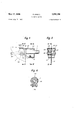
- FIG. l is a longitudinal section through an embodiment of the Skinning tool according to the invention.
- FIG. 2 is la section on the line II-Il in FIG. l;
- FIGS. 3a and 3b show diagrammatically two different ways of guiding the knife blade
- FIG. 4 is a partial longitudinal section through another embodiment of the invention.
- FIG. 5 is a cross-section on the line V-V in FIG. 4.
- FIG. 6 is a cross-section on the line VI-VI in FIG. 4.
- a motor (not shown), e.g. a pneumatic motor is provided and connected with a carrier means or spindle 1 in such a manner as to impart to said spindle a reciprocating movement.
- a stop ring 1a is mounted on the spindle 1 and, on its front end 1b which is of slightly conical shape, a blade holder 2 is mounted which is clamped to the spindle by means of a bolt 2a.
- the blader holder 2 is vrigidly conthe bearing support 11 lies.
- a screw 23 is fixed in the bracket 13, which clamps a square-headed tubular distance piece 24.
- Two pins 25, about which a lever 26 pivots, are pressed into the head portion of the distance piece 24.
- the lever 26 carries two cams 27 at one end which, .in the normal position of the lever 26 shown, press on to a spring steel plate 28, which forms part of a removable blade protector comprising two protector members 14a, 14b which are riveted or screwed together and provided with teeth 15.
- the plate28 lies on the collars 29 of two adjusting screws 30, 31 which are disposed between the members 14a, 14b and bot-h have knu'rled heads so that they can be easily adjusted by hand. l
- the screw 30 contacts the bearing support 11 which lies on the bracket 13.
- the screw 31 has a point 32 which rests in a conical recess 33 of a slide member 34, which also lies on' the bracket 13. Instead of a point 32 the screw 31 could also have a hemispherical end and the recess 33 could be correspondingly shaped.
- the slide member 34 has an oblique face 35 ⁇ and its slotted rear wall engages the groove 37 of a knurled screw whose axis is parallel to the driving spindle 1, and which is screwed into a bridge 21 which in turn is rigidly connected with the support member 16.
- a pretensioned tension spring 18 connects the plate 28 with the bridge 21.
- the Skinning knife is adjusted as follows:
- the blade protector members 14a, 14b can 'be raised or lowered relative t-o the blade 3.
- the angular position of the blade 3 can be varied.
- the slide member 34 and thereby also the blade protector members 14a, 14b are displaced along the blade 3.
- the blade protector members can be adjusted in such a way that the cutting edge of .the blade 3 does no-t protrude anywhere beyond the teeth 15.
- the lever 26 is pivoted from the position shown in FIGURE 1 about the pins 25 so that the cams 27 no longer engage the plate 28.
- the spring 18 then pulls the blade protector members 14a, 14b rearwardly and upwardly over the oblique face 3'5 so that the blade is exposed in the region of its cutting edge for sharpening.
- the blade protector mem- Patented May 17, 1966 ber slides back into its original position.
- the lever 26 can be constructed in such a way that it secures the adjusting screw 36 against displacement when the former is in its closed position.
- FIG. 3a The suspension of the knife blade 3 by the link 8 is shown diagrammatically in FIG. 3a.
- the driving spindle connection is slightly deformed resiliently in the course of its reciprocating movement.
- the cutting edge of the blade of which three points A, B, C are emphasized in FIGS. 3a and 3b, describes a two-dimensional curved movement at its straight portion yas well as its front curved portion which has its maximum velocity in its most effective position in the region of the tooth apices.
- the tooth apex A traverses a longer path than the points B and C of the cutting edge of the blade, whereby the cutting effect in this region is increased, which is labor saving for the operator.
- the blade could, as shown diagrammatically in FIG. 3b, also be suspended by two links 8 and 8a, which could be of different length.
- This construction results in the points A, B, C describing movements which follow different curves, the individual points passing through their lowest positions at dilerent times.
- the same kind of movement of the blade could also be achieved by guide curves instead of links.
- the blade 3 and its mounting constitute working parts which have to be exchanged after a cert-ain operating period because of wear.
- This can be done ina simple manner by releasing the screw 23, unhooking the spring 18 and withdrawing the blade protector members 14a, 14b from the bracket 13.
- the bolt 2a is released from the now exposed blade, the bearing support 11 is raised over the oblique face 19 of the bracket 13 andthe blade 3 is withdrawn from the spindle 1.
- the procedure is reversed.
- the tooth pitch i.e. the distance between two teeth on one side member of the blade protector should be not more than 8 mm.
- the so-called gliding angle a i.e. the angle between the line connecting two tooth apices and the tangent to the recess curve in a tooth apex may not exceed 60".
- the thickness of the blade 3 should be no more than 0.7 mm.
- the slot k between the members 14a and 14b (FIG. 2) may not exceed 0.9 mm.
- the difference between the blade guide slot k and the thickness of the blade 3 may not exceed 0.45 mm.
- LFIGS. 4 to 6 show a different means for xing the blade to the driving spindle.
- the stepped bolt 38 which carries the sleeve 39 is inserted in a borein the blade 3.
- the blade, bolt and sleeve are held together by riveting.
- the two bearings 40 are rotatably mounted on the bolt 38 and the sleeve 39 respectively on either side of the blade 3.
- the U-shaped tensioning-spring 41 has co-axial bores in its two legs in which the ends of the bolt 38 and sleeve 39 respectively are supported.
- the blade 3 has a recess 42 with which the bridge portion of the tensioning spring 41 engages. This recess serves for guiding the bridge portion of the spring 41 and for carrying the latter .along with it when t-he blade 3 is rotated.
- the blade holder 43 which is advantageously made of a synthetic material such as nylon or the like, has at its rear end a slotted hub 44. With the aid of a clip 45 and a screw 46 the hub is clamped on to the drivin-g spindle 1. ⁇
- the head of t-he blade holder 43 into which the blade 3 is inserted has an open recess for receiving the journals 40.
- the outer face of the head of the blade holder is in t-he form of a cam 48.
- the bridge portion of the tensioning spring 41 cooperates with .the cam 48, namely, with its outermost face 49 thereof w-hich is concentric with the recess 47, and presses the bearings 40'which are rotatably arranged on the blade 3, into the recess 47 of the blade holder 43.
- the blade 3 is released, namely in the above described manner.
- the bearing support 11 is raised over the oblique face 19 of the bracket 13 lalong the now released 'blade 3.
- the blade 3 is then rotated downwards on its ⁇ bearings 40 and carries the tensioning spring 41 with it.
- the latter slides over the portion 49 of the cam 48 and is gradually released by the face 50 of the cam 48 upon further rotation.
- the blade 3 with its bearing 40 can then be withdrawn from the recess 47 of the blade holder 43.
- a knife blade having ya cutting edge, support means for said knife blade, reciprocatory carrier means mounted in said support means for reciprocatory movement relative thereto, connecting means pivotally securing one end of said knife ⁇ blade to said carrier means, protective means mounted on said support means in straddling relation to the knife blade and having toothed edges extending along the knife blade adjacent the cutting edge thereof, means for adjustment of the position of said protective means relative to said support means, and guide means rockably connecting said knife blade at a point spaced from said carrier means with said support means and during the reciprocation of the knife blade causing a point on sa'id cutting edge of the knife blade to follow a curve deviating from a line connecting the points of the teeth.
- said detachable clamping means includes leaf spring means having a portion thereof bent to form a loop receiving said bearing and a second portion extending from said loop portion, a pin secured to said second portion of the leaf spring means, and a recess in said bracket means for receiving said pin.
Landscapes
- Life Sciences & Earth Sciences (AREA)
- Engineering & Computer Science (AREA)
- Food Science & Technology (AREA)
- Harvester Elements (AREA)
- Details Of Cutting Devices (AREA)
- Knives (AREA)
- Treatment Of Fiber Materials (AREA)
Applications Claiming Priority (1)
| Application Number | Priority Date | Filing Date | Title |
|---|---|---|---|
| CH887962A CH402638A (de) | 1962-07-24 | 1962-07-24 | Enthäutungsmesser |
Publications (1)
| Publication Number | Publication Date |
|---|---|
| US3251129A true US3251129A (en) | 1966-05-17 |
Family
ID=4345778
Family Applications (1)
| Application Number | Title | Priority Date | Filing Date |
|---|---|---|---|
| US294477A Expired - Lifetime US3251129A (en) | 1962-07-24 | 1963-07-12 | Skinning knife |
Country Status (4)
| Country | Link |
|---|---|
| US (1) | US3251129A (de) |
| CH (1) | CH402638A (de) |
| DE (1) | DE1283115C2 (de) |
| GB (1) | GB1046945A (de) |
Cited By (3)
| Publication number | Priority date | Publication date | Assignee | Title |
|---|---|---|---|---|
| US3388470A (en) * | 1965-04-07 | 1968-06-18 | Ufer Willy | Power knife |
| USD348184S (en) | 1992-09-30 | 1994-06-28 | The Scott Fetzer Company | Electric fillet knife handle and blade |
| US6678959B1 (en) * | 1999-07-09 | 2004-01-20 | Midwest Trade Tool, Inc. | Grout removal tool |
Citations (3)
| Publication number | Priority date | Publication date | Assignee | Title |
|---|---|---|---|---|
| US1505030A (en) * | 1922-07-13 | 1924-08-12 | George F Kentch | Drag saw |
| US2692621A (en) * | 1948-08-18 | 1954-10-26 | Ezekiel C Steiner | Carcass splitting saw |
| US2911717A (en) * | 1956-02-23 | 1959-11-10 | Knoll Fritz | Cutting tool having a retractable protective casing |
Family Cites Families (3)
| Publication number | Priority date | Publication date | Assignee | Title |
|---|---|---|---|---|
| DE606340C (de) * | 1934-11-30 | Julius Geiger G M B H | Enthaeutungsvorrichtung | |
| DE642331C (de) * | 1935-09-29 | 1937-03-01 | Fried Krupp Akt Ges | Enthaeutungsvorrichtung |
| DE906544C (de) * | 1951-12-01 | 1954-09-27 | Fritz Knoll | Enthaeutungsmesser |
-
1962
- 1962-07-24 CH CH887962A patent/CH402638A/de unknown
-
1963
- 1963-07-03 DE DE19631283115 patent/DE1283115C2/de not_active Expired
- 1963-07-12 US US294477A patent/US3251129A/en not_active Expired - Lifetime
- 1963-07-23 GB GB29106/63A patent/GB1046945A/en not_active Expired
Patent Citations (3)
| Publication number | Priority date | Publication date | Assignee | Title |
|---|---|---|---|---|
| US1505030A (en) * | 1922-07-13 | 1924-08-12 | George F Kentch | Drag saw |
| US2692621A (en) * | 1948-08-18 | 1954-10-26 | Ezekiel C Steiner | Carcass splitting saw |
| US2911717A (en) * | 1956-02-23 | 1959-11-10 | Knoll Fritz | Cutting tool having a retractable protective casing |
Cited By (3)
| Publication number | Priority date | Publication date | Assignee | Title |
|---|---|---|---|---|
| US3388470A (en) * | 1965-04-07 | 1968-06-18 | Ufer Willy | Power knife |
| USD348184S (en) | 1992-09-30 | 1994-06-28 | The Scott Fetzer Company | Electric fillet knife handle and blade |
| US6678959B1 (en) * | 1999-07-09 | 2004-01-20 | Midwest Trade Tool, Inc. | Grout removal tool |
Also Published As
| Publication number | Publication date |
|---|---|
| GB1046945A (en) | 1966-10-26 |
| DE1283115C2 (de) | 1973-12-06 |
| CH402638A (de) | 1965-11-15 |
| DE1283115B (de) | 1973-12-06 |
Similar Documents
| Publication | Publication Date | Title |
|---|---|---|
| US2735458A (en) | Buchmann | |
| US3646675A (en) | Motor-driven cutting device | |
| US3251129A (en) | Skinning knife | |
| US3523348A (en) | Holder for machine tools of flexible material having teeth or a cutting edge | |
| US2814104A (en) | Skin tensioning mechanism for shaving devices | |
| US3465795A (en) | Easily dressed sharpener | |
| SU581848A3 (ru) | Устройство дл закреплени сменной режущей вставки в держателе инструмента | |
| US2738579A (en) | Cutting device | |
| US2028293A (en) | Undercutting attachment for lathes | |
| US2726443A (en) | Skin tensioning accessory for shavers | |
| US1893916A (en) | Copying mechanism | |
| FR2470802A1 (fr) | Machine a cylindre a lames pour le traitement de peaux | |
| US2778106A (en) | Hair clipping implement | |
| US2109857A (en) | Tool for cleaning and deepening grooves in pistons | |
| US2207994A (en) | Pruning shears | |
| US1854111A (en) | Crosscut sawing machine | |
| US849252A (en) | Sheep-shears. | |
| US1749543A (en) | Hand hair clipper | |
| US1869101A (en) | Hair cutting machine | |
| US3204491A (en) | Machines for sharpening saws | |
| US1614554A (en) | Attachment for rod cigarette machines | |
| US1917727A (en) | Marker attachment for typewriters | |
| US3579828A (en) | Heavy-duty metal snips | |
| WO1983000836A1 (en) | Power sabre saw settable for forward or lateral sawing | |
| US2355602A (en) | Band-tool guide |