US3326501A - Suspension means for transverse automobile engines - Google Patents
Suspension means for transverse automobile engines Download PDFInfo
- Publication number
- US3326501A US3326501A US474720A US47472065A US3326501A US 3326501 A US3326501 A US 3326501A US 474720 A US474720 A US 474720A US 47472065 A US47472065 A US 47472065A US 3326501 A US3326501 A US 3326501A
- Authority
- US
- United States
- Prior art keywords
- engine
- chassis
- cushions
- vehicle
- transverse
- Prior art date
- Legal status (The legal status is an assumption and is not a legal conclusion. Google has not performed a legal analysis and makes no representation as to the accuracy of the status listed.)
- Expired - Lifetime
Links
- 239000000725 suspension Substances 0.000 title claims description 15
- 235000000396 iron Nutrition 0.000 description 9
- 229910000746 Structural steel Inorganic materials 0.000 description 5
- 230000006835 compression Effects 0.000 description 5
- 238000007906 compression Methods 0.000 description 5
- 239000002184 metal Substances 0.000 description 2
- 229910052751 metal Inorganic materials 0.000 description 2
- 230000001133 acceleration Effects 0.000 description 1
- 239000000853 adhesive Substances 0.000 description 1
- 230000001070 adhesive effect Effects 0.000 description 1
- 230000005540 biological transmission Effects 0.000 description 1
- 239000000463 material Substances 0.000 description 1
- 230000004048 modification Effects 0.000 description 1
- 238000012986 modification Methods 0.000 description 1
- 238000000926 separation method Methods 0.000 description 1
Images


Classifications
-
- B—PERFORMING OPERATIONS; TRANSPORTING
- B60—VEHICLES IN GENERAL
- B60K—ARRANGEMENT OR MOUNTING OF PROPULSION UNITS OR OF TRANSMISSIONS IN VEHICLES; ARRANGEMENT OR MOUNTING OF PLURAL DIVERSE PRIME-MOVERS IN VEHICLES; AUXILIARY DRIVES FOR VEHICLES; INSTRUMENTATION OR DASHBOARDS FOR VEHICLES; ARRANGEMENTS IN CONNECTION WITH COOLING, AIR INTAKE, GAS EXHAUST OR FUEL SUPPLY OF PROPULSION UNITS IN VEHICLES
- B60K5/00—Arrangement or mounting of internal-combustion or jet-propulsion units
- B60K5/12—Arrangement of engine supports
- B60K5/1208—Resilient supports
-
- B—PERFORMING OPERATIONS; TRANSPORTING
- B60—VEHICLES IN GENERAL
- B60K—ARRANGEMENT OR MOUNTING OF PROPULSION UNITS OR OF TRANSMISSIONS IN VEHICLES; ARRANGEMENT OR MOUNTING OF PLURAL DIVERSE PRIME-MOVERS IN VEHICLES; AUXILIARY DRIVES FOR VEHICLES; INSTRUMENTATION OR DASHBOARDS FOR VEHICLES; ARRANGEMENTS IN CONNECTION WITH COOLING, AIR INTAKE, GAS EXHAUST OR FUEL SUPPLY OF PROPULSION UNITS IN VEHICLES
- B60K5/00—Arrangement or mounting of internal-combustion or jet-propulsion units
- B60K5/04—Arrangement or mounting of internal-combustion or jet-propulsion units with the engine main axis, e.g. crankshaft axis, transversely to the longitudinal centre line of the vehicle
-
- B—PERFORMING OPERATIONS; TRANSPORTING
- B60—VEHICLES IN GENERAL
- B60K—ARRANGEMENT OR MOUNTING OF PROPULSION UNITS OR OF TRANSMISSIONS IN VEHICLES; ARRANGEMENT OR MOUNTING OF PLURAL DIVERSE PRIME-MOVERS IN VEHICLES; AUXILIARY DRIVES FOR VEHICLES; INSTRUMENTATION OR DASHBOARDS FOR VEHICLES; ARRANGEMENTS IN CONNECTION WITH COOLING, AIR INTAKE, GAS EXHAUST OR FUEL SUPPLY OF PROPULSION UNITS IN VEHICLES
- B60K5/00—Arrangement or mounting of internal-combustion or jet-propulsion units
- B60K5/12—Arrangement of engine supports
- B60K5/1208—Resilient supports
- B60K5/1216—Resilient supports characterised by the location of the supports relative to the motor or to each other
-
- F—MECHANICAL ENGINEERING; LIGHTING; HEATING; WEAPONS; BLASTING
- F02—COMBUSTION ENGINES; HOT-GAS OR COMBUSTION-PRODUCT ENGINE PLANTS
- F02F—CYLINDERS, PISTONS OR CASINGS, FOR COMBUSTION ENGINES; ARRANGEMENTS OF SEALINGS IN COMBUSTION ENGINES
- F02F7/00—Casings, e.g. crankcases
- F02F7/0082—Mounting of engine casings
Definitions
- ABSTRACT OF THE DISCLOSURE A chassis having an engine transversely mounted thereon by means of three flexible xing devices; two of which fixing devices are attached to side members of the chassis on one side of the axis of rotation of the engine, while the third xing device is attached to a cross member of the chassis on the other side of the axis of rotation.
- the present invention relates to suspension means for transversely arranged automobile engines, i.e. where the engine is arranged transversely of the longitudinal axis of the vehicle.
- the engine suspension is of particular importance because its function is not only to stop engine vibrations being transmitted to the body of the vehicle, but also to sustain the starting and bucking stresses, due to acceleration and braking.
- the cushions comprising the engine fixing members have a relatively good, but variable exibili whilst presenting a maximum resistance to wrenching and to clearance limited in the transverse direction, because a exibility which is too great in this sense, could harm the good operation of the vehicle.
- a transverse engine unit comprising an engine, clutch, a gear-box and a dierential, is fixed at three points to the chassis or body of the vehicle, two of these points being situated on one side of the axis of rotation of the engine unit and the other point on the other side of said axis.
- the rst two tixing devices connect the timing-case cover of the engine, and the gear box to the chassis or body of the vehicle, whilst the third iixing device situated at a point close to the centre of the engine, connects the casing of the latter to the chassis or body, by means of an intermediate arm.
- the fixing devices are, constituted by blocks or cushions operating both in compression and in shear, their compression and shear characteristics being combined to that they have a variable exibility.
- FIGURE l shows a schematic side view of an engine unit suspension according to the invention
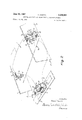
- FIGURE 2 shows a perspective schematic showing of the placements of a suspension according to the invention
- FIGURE 3 shows a section along the line III-III of FIGURE l
- FIGURE 4 shows a section along the line IV-IV of FIGURE 1.
- FIG- URES l and 2 the axis 1a of an engine unit 1, shown schematically, is arranged transversely with respect to the longitudinal axis of a motor vehicle, the chassis 2 of which is shown only schematically and partially by side members 7 and a cross member 8.
- the engine unit which comprises an engine, gear box, a clutch and differential, all being integrated, is shown as being of the type having inclined cylinders, the cylinders, clutch and gear box being in line.
- this engine unit 1 is fixed at three points 3, 4 and 5 to the chassis or body 2 of the vehicle. Two of these points 3, 4 are arranged for exam-ple towards the front of the vehicle. They are constituted by fixing devices 3, 4 situated on either side of the vehicle and which will be hereinafter described in greater detail, as well as by metal mounts 6, for example secured on the one hand to the timing case of the engine (not shown) and on the other hand to the gear box shell (not shown).
- the devices 3, 4 are on the other hand xed by means of a strap 7a, to side members 7 of the chassis or body 2.
- the rear fixing device 5 is connected on the one -hand by means of a lug 8a to the cross member 8 of the chassis or body 2 and, on the other hand, to an arm 9 which is itself xed to the engine unit 1, preferably towards the centre of the block, at two points 10 and 11, the distance therebetween being suflicient in order to give the assembly a maximum solidity.
- Each comprise two blocks or cushions 12, 13 of rubber or other flexible material arranged one above the other.
- Each block or cushion 12, 13 is arranged between two angle irons 14, 15 symmetrically opposite with respect to the axis of the block 12, 13-
- One angle iron 14 for each stress is fixed to the chassis or body 2 on a side member 7 or on a cross member 8, as the case may be and the other angle iron 15 is fixed to the engine unit by means of either the arm 6 or the arm 9, as the case may be.
- the angle irons 15 of each pair of cushions 12, 13 are juxtaposed so that one of the two lianges of each angle iron 15 touch one another by their backs.
- the flexible blocks or cushions 12, 13 are tixed to the angle irons 14, 15 by adhesives or by any other means and they each have two grooves 16, 17 having the desired shape in order to enable them to operate in shear. These grooves 16, 17 are situated in the diagonal of the Cushion 12 or 13, which diagonal is transverse with respect to that passing through the summits of the angle irons 14, 15.
- the cushions of each pair of cushions 12, 13 and the grooves 16, 17 which are arranged therein are arranged in such a manner that the grooves 17 are juxtaposed.
- the section of the cushion 12, 13 in the vertical direction is such that they may operate simultaneously n the vertical direction, which is that of the transmission of the main stresses between the engine unit 1 and the body 2, the one hand in compression and on the other hand in shear. But it will be noted that their shear diminishes whilst their compression increases, the
- the strap 8a xing the cushions 12, 13 of the support on the cross member 8 is mounted so that it exerts a prestress on the cushions 12, 13 ofsaid support 5. It has been noted that the rubber which has thus been prestressed operates under the best conditions.
- a chassis of a vehicle a suspension system and an engine unit transversely mounted within said chassis including two side members and a cross member, said suspension system comprising three ixing devices, means for securing each of said fixing devices to said engine unit and said chassis respectively, two of said devices being located on said side members and on one side of the rotation axis of said engine unit and the third of said devices being located on said cross member and on the otoher side of said rotation axis.
- each of said xing devices is constituted by two superposed flexible blocks slightly inclined with respect to the vertical, capable of operating both in compression and shear, each device having a pair of angle irons arranged between the blocks symmetrically opposite with respect to the axis of said blocks', each of said blocks having two grooves formed in the diagonal of the blocks; said diagonal being transversal with respect to a line passing through the summit of said angle irons.
Landscapes
- Engineering & Computer Science (AREA)
- Chemical & Material Sciences (AREA)
- Combustion & Propulsion (AREA)
- Mechanical Engineering (AREA)
- Transportation (AREA)
- General Engineering & Computer Science (AREA)
- Arrangement Or Mounting Of Propulsion Units For Vehicles (AREA)
- Arrangement Of Transmissions (AREA)
Applications Claiming Priority (1)
| Application Number | Priority Date | Filing Date | Title |
|---|---|---|---|
| FR983387A FR1411771A (fr) | 1964-07-29 | 1964-07-29 | Dispositif de suspension pour un bloc-moteur disposé transversalement par rapport à l'axe longitudinal d'un véhicule automobile |
Publications (1)
| Publication Number | Publication Date |
|---|---|
| US3326501A true US3326501A (en) | 1967-06-20 |
Family
ID=8835615
Family Applications (1)
| Application Number | Title | Priority Date | Filing Date |
|---|---|---|---|
| US474720A Expired - Lifetime US3326501A (en) | 1964-07-29 | 1965-07-26 | Suspension means for transverse automobile engines |
Country Status (6)
| Country | Link |
|---|---|
| US (1) | US3326501A (fr) |
| BE (1) | BE665775A (fr) |
| ES (1) | ES315002A1 (fr) |
| FR (1) | FR1411771A (fr) |
| GB (1) | GB1113873A (fr) |
| OA (1) | OA02011A (fr) |
Cited By (18)
| Publication number | Priority date | Publication date | Assignee | Title |
|---|---|---|---|---|
| US3430901A (en) * | 1967-07-20 | 1969-03-04 | Andre Cauvin | Mounting device for the engine block of a vehicle |
| US3565373A (en) * | 1969-10-29 | 1971-02-23 | Gen Motors Corp | Engine mount assembly |
| US3624122A (en) * | 1966-06-24 | 1971-11-30 | Gen Mills Inc | Alicyclic diisocyanates |
| FR2139342A5 (fr) * | 1971-05-10 | 1973-01-05 | Honda Motor Co Ltd | |
| US3730462A (en) * | 1972-04-26 | 1973-05-01 | Gen Motors Corp | Engine mount assembly |
| US3894604A (en) * | 1972-03-28 | 1975-07-15 | Citroen Sa | Automobile vehicles |
| US4047588A (en) * | 1975-12-22 | 1977-09-13 | Kawasaki Motors Corporation U.S.A. | Snowmobile engine mount |
| US4089385A (en) * | 1975-11-27 | 1978-05-16 | Regie Nationale Des Usines Renault | Device for binding an engine to a vehicle chassis or body |
| US4240517A (en) * | 1979-04-13 | 1980-12-23 | General Motors Corporation | Powertrain and independent suspension mounting arrangement for front-wheel-drive vehicle |
| US4487287A (en) * | 1981-08-03 | 1984-12-11 | Mazda Motor Corporation | Support system for automobile power plant |
| US4504036A (en) * | 1980-06-16 | 1985-03-12 | Ford Motor Company | Engine mount preloaded in shear |
| US4560027A (en) * | 1982-11-09 | 1985-12-24 | Nissan Motor Co., Ltd. | Power unit supporting structure |
| US5570757A (en) * | 1993-11-22 | 1996-11-05 | Textron Inc. | Engine mounting system for a car |
| DE10018000A1 (de) * | 2000-04-11 | 2001-10-25 | Behr Gmbh & Co | Lager für ein elastisch anzuordnendes Bauteil |
| US20160368359A1 (en) * | 2014-02-24 | 2016-12-22 | Mahindra And Mahindra Limited | An arrangement for packaging an engine of a vehicle |
| CN108312830A (zh) * | 2018-03-22 | 2018-07-24 | 南京世界村汽车动力有限公司 | 一种汽车发动机悬置装置 |
| CN108506109A (zh) * | 2017-02-24 | 2018-09-07 | 丰田纺织株式会社 | 树脂制罩的拆卸构造和树脂制罩 |
| WO2022057984A1 (fr) * | 2020-09-15 | 2022-03-24 | Contitech Vibration Control Gmbh | Système de montage d'assemblage |
Families Citing this family (4)
| Publication number | Priority date | Publication date | Assignee | Title |
|---|---|---|---|---|
| JPS5863519A (ja) * | 1981-10-12 | 1983-04-15 | Nissan Motor Co Ltd | パワ−ユニツトのマウンテイング装置 |
| FR2540800A1 (fr) * | 1983-02-16 | 1984-08-17 | Peugeot | Ensemble de propulsion pour vehicule automobile a deux essieux moteurs |
| US20070210497A1 (en) * | 2006-02-28 | 2007-09-13 | Textron Inc. | Front engine isolator mount |
| CN107640013B (zh) * | 2017-09-18 | 2021-01-01 | 芜湖金智王机械设备有限公司 | 一种机动车发动机悬置 |
Citations (3)
| Publication number | Priority date | Publication date | Assignee | Title |
|---|---|---|---|---|
| US2076034A (en) * | 1934-03-29 | 1937-04-06 | Gen Motors Corp | Engine mounting |
| US2257804A (en) * | 1939-04-17 | 1941-10-07 | Lord Mfg Co | Joint |
| US2329829A (en) * | 1942-07-27 | 1943-09-21 | Gen Motors Corp | Engine mounting |
-
1964
- 1964-07-29 FR FR983387A patent/FR1411771A/fr not_active Expired
-
1965
- 1965-06-22 OA OA52071A patent/OA02011A/fr unknown
- 1965-06-22 BE BE665775D patent/BE665775A/xx unknown
- 1965-07-06 ES ES0315002A patent/ES315002A1/es not_active Expired
- 1965-07-26 US US474720A patent/US3326501A/en not_active Expired - Lifetime
- 1965-07-29 GB GB32561/65A patent/GB1113873A/en not_active Expired
Patent Citations (3)
| Publication number | Priority date | Publication date | Assignee | Title |
|---|---|---|---|---|
| US2076034A (en) * | 1934-03-29 | 1937-04-06 | Gen Motors Corp | Engine mounting |
| US2257804A (en) * | 1939-04-17 | 1941-10-07 | Lord Mfg Co | Joint |
| US2329829A (en) * | 1942-07-27 | 1943-09-21 | Gen Motors Corp | Engine mounting |
Cited By (19)
| Publication number | Priority date | Publication date | Assignee | Title |
|---|---|---|---|---|
| US3624122A (en) * | 1966-06-24 | 1971-11-30 | Gen Mills Inc | Alicyclic diisocyanates |
| US3430901A (en) * | 1967-07-20 | 1969-03-04 | Andre Cauvin | Mounting device for the engine block of a vehicle |
| US3565373A (en) * | 1969-10-29 | 1971-02-23 | Gen Motors Corp | Engine mount assembly |
| FR2139342A5 (fr) * | 1971-05-10 | 1973-01-05 | Honda Motor Co Ltd | |
| US3894604A (en) * | 1972-03-28 | 1975-07-15 | Citroen Sa | Automobile vehicles |
| US3730462A (en) * | 1972-04-26 | 1973-05-01 | Gen Motors Corp | Engine mount assembly |
| US4089385A (en) * | 1975-11-27 | 1978-05-16 | Regie Nationale Des Usines Renault | Device for binding an engine to a vehicle chassis or body |
| US4047588A (en) * | 1975-12-22 | 1977-09-13 | Kawasaki Motors Corporation U.S.A. | Snowmobile engine mount |
| US4240517A (en) * | 1979-04-13 | 1980-12-23 | General Motors Corporation | Powertrain and independent suspension mounting arrangement for front-wheel-drive vehicle |
| US4504036A (en) * | 1980-06-16 | 1985-03-12 | Ford Motor Company | Engine mount preloaded in shear |
| US4487287A (en) * | 1981-08-03 | 1984-12-11 | Mazda Motor Corporation | Support system for automobile power plant |
| US4560027A (en) * | 1982-11-09 | 1985-12-24 | Nissan Motor Co., Ltd. | Power unit supporting structure |
| US5570757A (en) * | 1993-11-22 | 1996-11-05 | Textron Inc. | Engine mounting system for a car |
| DE10018000A1 (de) * | 2000-04-11 | 2001-10-25 | Behr Gmbh & Co | Lager für ein elastisch anzuordnendes Bauteil |
| DE10018000B4 (de) * | 2000-04-11 | 2004-03-11 | Behr Gmbh & Co. | Lager für ein elastisch anzuordnendes Bauteil |
| US20160368359A1 (en) * | 2014-02-24 | 2016-12-22 | Mahindra And Mahindra Limited | An arrangement for packaging an engine of a vehicle |
| CN108506109A (zh) * | 2017-02-24 | 2018-09-07 | 丰田纺织株式会社 | 树脂制罩的拆卸构造和树脂制罩 |
| CN108312830A (zh) * | 2018-03-22 | 2018-07-24 | 南京世界村汽车动力有限公司 | 一种汽车发动机悬置装置 |
| WO2022057984A1 (fr) * | 2020-09-15 | 2022-03-24 | Contitech Vibration Control Gmbh | Système de montage d'assemblage |
Also Published As
| Publication number | Publication date |
|---|---|
| OA02011A (fr) | 1970-05-05 |
| FR1411771A (fr) | 1965-09-24 |
| ES315002A1 (es) | 1966-01-01 |
| BE665775A (fr) | 1965-10-18 |
| GB1113873A (en) | 1968-05-15 |
Similar Documents
| Publication | Publication Date | Title |
|---|---|---|
| US3326501A (en) | Suspension means for transverse automobile engines | |
| US3368824A (en) | Vehicle suspension devices | |
| US3211491A (en) | Vehicle body shake absorber | |
| US3430901A (en) | Mounting device for the engine block of a vehicle | |
| EP0040327B1 (fr) | Structure de montage pour moteur de véhicule automobile | |
| EP0038532A2 (fr) | Structure de montage pour moteur | |
| US2020597A (en) | Engine mounting | |
| US2112628A (en) | Differential mounting | |
| US3290035A (en) | Vehicle spring system | |
| US2214942A (en) | Flexible mounting for reciprocating engines | |
| US4027909A (en) | Resilient mounting for vehicle bumper bar | |
| US2606021A (en) | Suspension | |
| US3018990A (en) | Elastic engine suspension especially for motor vehicles | |
| JPS61244626A (ja) | 自動車の推進軸支持装置 | |
| US3056569A (en) | Airplane engine suspension system | |
| US2888999A (en) | Motor vehicle transmission gear bracing means | |
| US2159332A (en) | Motor vehicle | |
| US1829676A (en) | Suspension of engines for self propelled road vehicles | |
| US2812175A (en) | Resilient mountings | |
| US2081965A (en) | Automotive vehicle | |
| US4706901A (en) | Propulsion unit suspension for vehicles, especially for propeller driven aircrafts | |
| US3153947A (en) | Vehicular steering mechanism | |
| US2017628A (en) | Means for resiliently mounting engines on automotive vehicles | |
| US2052009A (en) | Motor mounting | |
| US3305040A (en) | Automobile vehicles fitted with disc brakes |