US3335526A - Pipe scarfing tool - Google Patents
Pipe scarfing tool Download PDFInfo
- Publication number
- US3335526A US3335526A US426831A US42683165A US3335526A US 3335526 A US3335526 A US 3335526A US 426831 A US426831 A US 426831A US 42683165 A US42683165 A US 42683165A US 3335526 A US3335526 A US 3335526A
- Authority
- US
- United States
- Prior art keywords
- pipe
- tool
- housing
- scarfing
- pilot piece
- Prior art date
- Legal status (The legal status is an assumption and is not a legal conclusion. Google has not performed a legal analysis and makes no representation as to the accuracy of the status listed.)
- Expired - Lifetime
Links
- 238000005520 cutting process Methods 0.000 description 18
- 239000004744 fabric Substances 0.000 description 3
- 229910003460 diamond Inorganic materials 0.000 description 2
- 239000010432 diamond Substances 0.000 description 2
- 239000000428 dust Substances 0.000 description 2
- 239000003365 glass fiber Substances 0.000 description 2
- 238000004519 manufacturing process Methods 0.000 description 2
- 238000000034 method Methods 0.000 description 2
- 239000011347 resin Substances 0.000 description 2
- 229920005989 resin Polymers 0.000 description 2
- 239000000853 adhesive Substances 0.000 description 1
- 230000001070 adhesive effect Effects 0.000 description 1
- 230000004323 axial length Effects 0.000 description 1
- 239000004568 cement Substances 0.000 description 1
- 238000010276 construction Methods 0.000 description 1
- 238000005553 drilling Methods 0.000 description 1
- 230000000694 effects Effects 0.000 description 1
- 239000011521 glass Substances 0.000 description 1
- 238000007689 inspection Methods 0.000 description 1
- 238000009434 installation Methods 0.000 description 1
- 238000003754 machining Methods 0.000 description 1
- 239000000463 material Substances 0.000 description 1
- 238000012986 modification Methods 0.000 description 1
- 230000004048 modification Effects 0.000 description 1
- 230000035515 penetration Effects 0.000 description 1
- 239000000843 powder Substances 0.000 description 1
- 230000000717 retained effect Effects 0.000 description 1
Images
Classifications
-
- B—PERFORMING OPERATIONS; TRANSPORTING
- B23—MACHINE TOOLS; METAL-WORKING NOT OTHERWISE PROVIDED FOR
- B23B—TURNING; BORING
- B23B5/00—Turning-machines or devices specially adapted for particular work; Accessories specially adapted therefor
- B23B5/16—Turning-machines or devices specially adapted for particular work; Accessories specially adapted therefor for bevelling, chamfering, or deburring the ends of bars or tubes
- B23B5/167—Tools for chamfering the ends of bars or tubes
- B23B5/168—Tools for chamfering the ends of bars or tubes with guiding devices
-
- B—PERFORMING OPERATIONS; TRANSPORTING
- B24—GRINDING; POLISHING
- B24B—MACHINES, DEVICES, OR PROCESSES FOR GRINDING OR POLISHING; DRESSING OR CONDITIONING OF ABRADING SURFACES; FEEDING OF GRINDING, POLISHING, OR LAPPING AGENTS
- B24B9/00—Machines or devices designed for grinding edges or bevels on work or for removing burrs; Accessories therefor
- B24B9/007—Machines or devices designed for grinding edges or bevels on work or for removing burrs; Accessories therefor for end faces of tubes
-
- B—PERFORMING OPERATIONS; TRANSPORTING
- B29—WORKING OF PLASTICS; WORKING OF SUBSTANCES IN A PLASTIC STATE IN GENERAL
- B29C—SHAPING OR JOINING OF PLASTICS; SHAPING OF MATERIAL IN A PLASTIC STATE, NOT OTHERWISE PROVIDED FOR; AFTER-TREATMENT OF THE SHAPED PRODUCTS, e.g. REPAIRING
- B29C70/00—Shaping composites, i.e. plastics material comprising reinforcements, fillers or preformed parts, e.g. inserts
- B29C70/04—Shaping composites, i.e. plastics material comprising reinforcements, fillers or preformed parts, e.g. inserts comprising reinforcements only, e.g. self-reinforcing plastics
- B29C70/28—Shaping operations therefor
- B29C70/54—Component parts, details or accessories; Auxiliary operations, e.g. feeding or storage of prepregs or SMC after impregnation or during ageing
- B29C70/545—Perforating, cutting or machining during or after moulding
-
- B—PERFORMING OPERATIONS; TRANSPORTING
- B29—WORKING OF PLASTICS; WORKING OF SUBSTANCES IN A PLASTIC STATE IN GENERAL
- B29L—INDEXING SCHEME ASSOCIATED WITH SUBCLASS B29C, RELATING TO PARTICULAR ARTICLES
- B29L2023/00—Tubular articles
- B29L2023/22—Tubes or pipes, i.e. rigid
Definitions
- This invention relates to an improved scarfing tool and more particularly to a portable tool that will produce a taper on the end of a length of pipe.
- One method of securing an end fitting to a length of pipe is to taper the end of the pipe and cement the similarly tapered fitting thereto. Since the holding power of the joint so formed is due, at least in part, to the resulting inclined plane effect, it is imperative that the taper on the end of the pipe be accurately formed. This machining operation presents something of a problem particularly when it must be done in the field where shop facilities are not readily available.
- the present invention is directed towards a simple, low cost attachment that may be applied to a power driven tool such as a drill.
- a power driven tool such as a drill.
- a variety of cutting mediums may be employed such as an abrasive cloth, or a diamond cutter in the shape of a cone having the desired included angle.
- the cutting medium is of course readily removable and replaceable, the choice of cutters depending upon the nature of the material being shaped.
- the cutting memher is secured within a hollow, open ended housing having the desired taper on the inside diameter thereof.
- the housing surrounds, at least partially, a pilot piece having an outside diameter of such size as to assure a reasonably close fit with the inside diameter of the pipe to be machined.
- the pilot piece is hollow and is provided with end bearings so that a stem may be rotatably journaled therein.
- the housing is pinned to the stem in such a manner that the shank portion of the stem may be received in the chuck of a drill.
- the inside surface of the housing is concentrically spaced from the outside surface of the pilot piece. It should be further noted that while the stem and the housing are driven as a unit by the drill, the pilot piece does not rotate because of the ball bearing mounting arrangement. Thus the possibility of scoring the inside surface of the pipe is eliminated. Since one application of the improved scarfing tool is in the field of resin bonded glass fiber pipes, the bearings are of the sealed type and the housing is provided with several outlet ports for the fine glass powder that will result from the scarfing operation.
- the operation of the improved scarfing tool is relatively simple and its order of complexity, when secured in the chuck of a drill, is comparable to that encountered when drilling a hole.
- the pilot piece is inserted into the pipe end until the cutting surface makes contact with the outside surface of the pipe.
- the drill is then energized to begin the scarfing process.
- the proper tool pressure may be quickly determined by the operator and the tool may readily be removed without disturbing the concentric relationship of the tapered cutting member and the pilot piece. This permits frequent inspection of the work during the scarfing operation.
- the quality of the scarf produced by the apparatus of the present invention is superior to the scarf made by a blade.
- a rough finish may be eilected which is highly desirable in the production of a bonded joint.
- the degree of finish roughness may of course be varied to suit the particular application since the cutting medium is readily removable and replaceable.
- the tapered cutting cone is maintained concentric with the pilot piece so that the scarfing is similarly concentric.
- the axial length of the scarf is determined by the depth of penetration of the pilot piece into the pipe.
- Another object is to provide a scarfing tool that is utilized with a power driven hand tool.
- An additional object of the present invention is to provide that the cutting medium of the improved scarfing tool be readily removable and replaceable.
- a still further object is to provide means for centering and holding stationary the pipe to be cut while the scarfing tool rotates thereabout.
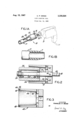
- FIG. 1A is a pictorial view, partly broken away and partly in phantom, illustrating the application of the present invention in combination with an electrically power driven hand drill;
- FIG. 1B is a fragmentary side elevation view, partly in section, of the scarfed end of a length of plastic pipe;
- FIG. 2 is a sectional side elevation view of the improved pipe scarfing tool
- FIG. 3 is a sectional side elevation view of an alternative housing for the improved scarfing tool.
- the scarfing tool 10 comprising the present invention is shown in combination with a hand drill D.
- Any of the conventional power sources may be utilized to drive the drill, there being shown the more usual line cord adapted to be plugged into a standard wall outlet.
- Chuck C of the drill holds the scarfing tool in a manner to be more fully described hereinafter.
- the outer surface of the end of the pipe P is tapered at T, as shown in FIG. 1B.
- a pipe such as may be fabricated from resin bonded glass fibers, will be used in conjunction with the scarfing tool.
- FIG. 2 illustrates the compactness and simplicity of the present invention.
- the scarfing tool 10 is provided with a central piloting shaft 14 proximate one end of which is secured a hollow, open end housing 12.
- pin 16 is driven through both housing 12 and shaft 14 so that this will then become a single unitary structure.
- Other means may also be employed to accomplish the same results.
- the shank end 18 of shaft 14 is adapted to fit into and be retained by chuck C of the drill and may therefore be provided with three equally spaced flats 20 as an optional feature.
- the opposite end 22 of shaft 14 which extends through and outwardly of the housing supports pilot piece 24. Bearings 26 are interposed between the pilot piece and the shaft so that the shaft may be rotated relative to the pilot piece. Threaded cap 28 serves to axially restrain the pilot piece, the outside diameter of which fits snugly into the inside diameter of the pipe to be machined.
- FIG. 2 illustrates the use of an abrasive cloth although as will be explained in connection with the next embodiment, an abrasive sleeve may also be used.
- the housing is further provided with a plurality of radial apertures 32 so that the dust resulting from the scarfing operation may be exhausted.
- the end of a length of pipe is supported on pilot piece 24, the opposite end of the pipe being suitably held such as in a clamp or vise (not shown).
- the scarfing tool 10 is then axially advanced while the housing is rotating so that the first end of the pipe enters the annular chamber 34 between the abrasive member and the pilot piece.
- the outside surface of the pipe will thereby be tapered and the shavings or dust will escape through apertures 32. It will be apparent then that while the housing and the shaft are rotated by the driving means, the pilot piece will not rotate because of the ball bearing mounting and therefore the inside surface of the pipe cannot be scored.
- FIG. 3 there is shown an alternative embodiment of the housing adapted for use with a rigid, sleevelike abrasive member such as a diamond cutter.
- Housing 40 is provided with an internal lip 42 against which bears one end of cutting sleeve 44.
- the opposite, flanged end 45 of the sleeve extends radially outward and is captured by means of a retainer 46.
- Screws 48 serve to hold the retainer 46 on the housing 40.
- the apparatus described hereinabove .and illustrated in the drawing is compact and simple to operate. It is inexpensive to manufacture and is adapted to accurately taper the end of a pipe even if that operation must be performed at the installation site where more sophisticated machine tools are not readily available.
- the construction of the tool is simple enough to permit the changeover from one abrasive cutting member to another.
- the tool is inexpensive enough to provide a range of tapers which may then be formed on the pipe end merely by interchanging the tool in the drill chuck.
- a pipe scarfing tool adapted to be driven by a power tool, said pipe scarfing tool comprising:
- the apparatus in accordance with claim 1 including means to removably retain said abrasive cutting member.
Landscapes
- Engineering & Computer Science (AREA)
- Mechanical Engineering (AREA)
- Chemical & Material Sciences (AREA)
- Composite Materials (AREA)
- Polishing Bodies And Polishing Tools (AREA)
- Drilling Tools (AREA)
Description
Aug. 15, 1967 P, W55 3,335,526
PIPE SCARFING TOOL Filed Jan. 21, 1965 INVENTOR. 'CHARLES P. WEI-55' A TTORIVE Y United States Patent 3,335,526 PIPE SCARFING TOOL Charles P. Weiss, Hempstead, N.Y., assignor to Koppers Company, Inc, a corporation of Delaware Filed Jan. 21, 1965, Ser. No. 426,831 6 Claims. (Cl. 51-73) This invention relates to an improved scarfing tool and more particularly to a portable tool that will produce a taper on the end of a length of pipe.
One method of securing an end fitting to a length of pipe is to taper the end of the pipe and cement the similarly tapered fitting thereto. Since the holding power of the joint so formed is due, at least in part, to the resulting inclined plane effect, it is imperative that the taper on the end of the pipe be accurately formed. This machining operation presents something of a problem particularly when it must be done in the field where shop facilities are not readily available.
The present invention is directed towards a simple, low cost attachment that may be applied to a power driven tool such as a drill. A variety of cutting mediums may be employed such as an abrasive cloth, or a diamond cutter in the shape of a cone having the desired included angle. The cutting medium is of course readily removable and replaceable, the choice of cutters depending upon the nature of the material being shaped.
In one form of the present invention, the cutting memher is secured within a hollow, open ended housing having the desired taper on the inside diameter thereof. The housing surrounds, at least partially, a pilot piece having an outside diameter of such size as to assure a reasonably close fit with the inside diameter of the pipe to be machined. The pilot piece is hollow and is provided with end bearings so that a stem may be rotatably journaled therein. The housing is pinned to the stem in such a manner that the shank portion of the stem may be received in the chuck of a drill.
As may best be seen in the drawing, the inside surface of the housing is concentrically spaced from the outside surface of the pilot piece. It should be further noted that while the stem and the housing are driven as a unit by the drill, the pilot piece does not rotate because of the ball bearing mounting arrangement. Thus the possibility of scoring the inside surface of the pipe is eliminated. Since one application of the improved scarfing tool is in the field of resin bonded glass fiber pipes, the bearings are of the sealed type and the housing is provided with several outlet ports for the fine glass powder that will result from the scarfing operation.
The operation of the improved scarfing tool is relatively simple and its order of complexity, when secured in the chuck of a drill, is comparable to that encountered when drilling a hole. The pilot piece is inserted into the pipe end until the cutting surface makes contact with the outside surface of the pipe. The drill is then energized to begin the scarfing process. The proper tool pressure may be quickly determined by the operator and the tool may readily be removed without disturbing the concentric relationship of the tapered cutting member and the pilot piece. This permits frequent inspection of the work during the scarfing operation.
The quality of the scarf produced by the apparatus of the present invention is superior to the scarf made by a blade. By the use of an extremely coarse abrasive cutter, a rough finish may be eilected which is highly desirable in the production of a bonded joint. The degree of finish roughness may of course be varied to suit the particular application since the cutting medium is readily removable and replaceable. At all times, however, the tapered cutting cone is maintained concentric with the pilot piece so that the scarfing is similarly concentric. As will be seen in the drawing, the axial length of the scarf is determined by the depth of penetration of the pilot piece into the pipe.
Accordingly, it is an object of the present invention to provide an improved, portable scarfing tool.
Another object is to provide a scarfing tool that is utilized with a power driven hand tool.
An additional object of the present invention is to provide that the cutting medium of the improved scarfing tool be readily removable and replaceable.
A still further object is to provide means for centering and holding stationary the pipe to be cut while the scarfing tool rotates thereabout.
These and other features, objects and advantages of the invention will, in part, be pointed out with particularity and will, in part, become obvious from the following more detailed description of the invention, taken in conjunction with the accompanying drawing, which forms an integral part thereof.
In the various figures of the drawing, like reference characters designate like parts.
In the drawing:
FIG. 1A is a pictorial view, partly broken away and partly in phantom, illustrating the application of the present invention in combination with an electrically power driven hand drill;
FIG. 1B is a fragmentary side elevation view, partly in section, of the scarfed end of a length of plastic pipe;
FIG. 2 is a sectional side elevation view of the improved pipe scarfing tool; and
FIG. 3 is a sectional side elevation view of an alternative housing for the improved scarfing tool.
Referring now to the drawing and particularly to FIG. 1A and FIG. 1B, the scarfing tool 10 comprising the present invention is shown in combination with a hand drill D. Any of the conventional power sources may be utilized to drive the drill, there being shown the more usual line cord adapted to be plugged into a standard wall outlet. Chuck C of the drill holds the scarfing tool in a manner to be more fully described hereinafter. As a result of the scarfing operation, the outer surface of the end of the pipe P is tapered at T, as shown in FIG. 1B. For purposes of illustration, a pipe, such as may be fabricated from resin bonded glass fibers, will be used in conjunction with the scarfing tool.
FIG. 2 illustrates the compactness and simplicity of the present invention. The scarfing tool 10 is provided with a central piloting shaft 14 proximate one end of which is secured a hollow, open end housing 12. At assembly, pin 16 is driven through both housing 12 and shaft 14 so that this will then become a single unitary structure. Other means may also be employed to accomplish the same results.
The shank end 18 of shaft 14 is adapted to fit into and be retained by chuck C of the drill and may therefore be provided with three equally spaced flats 20 as an optional feature. The opposite end 22 of shaft 14 which extends through and outwardly of the housing supports pilot piece 24. Bearings 26 are interposed between the pilot piece and the shaft so that the shaft may be rotated relative to the pilot piece. Threaded cap 28 serves to axially restrain the pilot piece, the outside diameter of which fits snugly into the inside diameter of the pipe to be machined.
The inside diameter of the housing is tapered, for example, at a 5 included angle and a cutting member 30 is secured thereto by means of an adhesive. FIG. 2 illustrates the use of an abrasive cloth although as will be explained in connection with the next embodiment, an abrasive sleeve may also be used. The housing is further provided with a plurality of radial apertures 32 so that the dust resulting from the scarfing operation may be exhausted.
In operation, the end of a length of pipe is supported on pilot piece 24, the opposite end of the pipe being suitably held such as in a clamp or vise (not shown). The scarfing tool 10 is then axially advanced while the housing is rotating so that the first end of the pipe enters the annular chamber 34 between the abrasive member and the pilot piece. The outside surface of the pipe will thereby be tapered and the shavings or dust will escape through apertures 32. It will be apparent then that while the housing and the shaft are rotated by the driving means, the pilot piece will not rotate because of the ball bearing mounting and therefore the inside surface of the pipe cannot be scored.
In FIG. 3, there is shown an alternative embodiment of the housing adapted for use with a rigid, sleevelike abrasive member such as a diamond cutter. Housing 40 is provided with an internal lip 42 against which bears one end of cutting sleeve 44. The opposite, flanged end 45 of the sleeve extends radially outward and is captured by means of a retainer 46. Screws 48 serve to hold the retainer 46 on the housing 40.
The apparatus described hereinabove .and illustrated in the drawing is compact and simple to operate. It is inexpensive to manufacture and is adapted to accurately taper the end of a pipe even if that operation must be performed at the installation site where more sophisticated machine tools are not readily available. The construction of the tool is simple enough to permit the changeover from one abrasive cutting member to another. The tool is inexpensive enough to provide a range of tapers which may then be formed on the pipe end merely by interchanging the tool in the drill chuck.
There has been disclosed heretofore the best embodiments of the invention presently contemplated and it is to be understood that various changes and modifications may be made by those skilled in the art without departing from the spirit of the invention.
What is claimed is:
1. A pipe scarfing tool adapted to be driven by a power tool, said pipe scarfing tool comprising:
(a) a shaft having first and second ends, said shaft first end being adapted to be secured to a power tool for rotation thereby;
(b) a hollow pilot piece mounted concentrically on said shaft second end, whereby said shaft is angularly displaceable relative to said pilot piece, the pipe to be scarfed being seatable on said pilot piece outer surface;
(c) a hollow, open ended housing rigidly secured to said shaft in concentric relationship thereabout, said housing concentrically enveloping at least a portion of said pilot piece, said housing having a tapered inside diameter; and
(d) an abrasive cutting member positioned on the inside surface of said housing in confronting relationship to the outer surface of said pilot piece to define a concentrically tapered, annular cutting chamber thereabout.
2. The apparatus in accordance with claim 1 including bearing means interposed between said pilot piece and said shaft.
3. The apparatus in accordance with claim 1 wherein said housing is provided with a plurality of radial apertures for the egress of the cuttings resulting from the scarfing operation.
4. The apparatus of claim 1 wherein said cutting member is an abrasive cloth adhesively secured to the inside surface of said housing.
5. The apparatus in accordance with claim 1 including means to removably retain said abrasive cutting member.
6. The apparatus in accordance with claim 1 wherein the inside surface of said housing includes an inwardly depending lip, wherein said abrasive cutting member is a rigid, tapered sleeve in abutment at one end with said lip and wherein said housing includes means to retain said cutting member within said housing.
References Cited UNITED STATES PATENTS 704,428 7/1902 Allen 5l-73 2,595,541 5/1952 Riordan l44205 2,746,497 5/ 1956 Thompson l44205 3,188,674 6/1965 Hobbs 5l73 X 3,266,345 8/ 1966 Weisner 144-205 ROBERT C. RIORDON, Primary Examiner.
D. G. KELLY, Assistant Examiner.
Priority Applications (1)
| Application Number | Priority Date | Filing Date | Title |
|---|---|---|---|
| US426831A US3335526A (en) | 1965-01-21 | 1965-01-21 | Pipe scarfing tool |
Applications Claiming Priority (1)
| Application Number | Priority Date | Filing Date | Title |
|---|---|---|---|
| US426831A US3335526A (en) | 1965-01-21 | 1965-01-21 | Pipe scarfing tool |
Publications (1)
| Publication Number | Publication Date |
|---|---|
| US3335526A true US3335526A (en) | 1967-08-15 |
Family
ID=23692379
Family Applications (1)
| Application Number | Title | Priority Date | Filing Date |
|---|---|---|---|
| US426831A Expired - Lifetime US3335526A (en) | 1965-01-21 | 1965-01-21 | Pipe scarfing tool |
Country Status (1)
| Country | Link |
|---|---|
| US (1) | US3335526A (en) |
Cited By (22)
| Publication number | Priority date | Publication date | Assignee | Title |
|---|---|---|---|---|
| US3722146A (en) * | 1971-03-02 | 1973-03-27 | L Rodriguez | Device for sharpening the tapered points of dental instruments |
| DE2909545A1 (en) * | 1978-03-14 | 1979-09-27 | Myung Sung Kim | PORTABLE GRINDING DEVICE |
| US4483222A (en) * | 1981-08-28 | 1984-11-20 | Davis Dalton W | Pipe reaming device |
| FR2629753A1 (en) * | 1988-04-06 | 1989-10-13 | Bertin & Cie | Composite-material component and its method of manufacture |
| US4914866A (en) * | 1984-11-29 | 1990-04-10 | American Telephone And Telegraph Co. | Apparatus for adjusting optical fiber connector components |
| GB2241450A (en) * | 1990-03-01 | 1991-09-04 | Frank James Grundy | Chamfering tools |
| US5056265A (en) * | 1990-02-27 | 1991-10-15 | Hurst Richard H | Tube end abrading tool |
| US6074282A (en) * | 1997-03-26 | 2000-06-13 | Sunnen Products Company | External hone and method of making and using the same |
| WO2002064313A1 (en) * | 2001-02-14 | 2002-08-22 | Wayne Edmund Dinsdale | Apparatus for conditioning a surface of an object |
| US20060269371A1 (en) * | 2005-05-11 | 2006-11-30 | John Cassity | Pipe-Tapering Device |
| EP1787743A1 (en) * | 2005-11-18 | 2007-05-23 | HDS Hydraulik GmbH & Co. KG | Stripping tool for hoses and method of stripping reinforced hoses |
| GB2453791A (en) * | 2007-10-20 | 2009-04-22 | Armeg Ltd | Abrasive tool for chamfering plastic pipes |
| GB2458174A (en) * | 2008-03-08 | 2009-09-09 | Alexander Ramsay | A Pipe Chamfer |
| US20140321933A1 (en) * | 2013-04-24 | 2014-10-30 | Maik ROSENBERG | Peeling device |
| GB2527198A (en) * | 2014-05-08 | 2015-12-16 | Keah Products Ltd | Cutting arrangement |
| US9440292B1 (en) * | 2012-01-13 | 2016-09-13 | Rph Enterprises, Inc. | Disposable surgical rod deburrer |
| US9459082B2 (en) * | 2014-07-17 | 2016-10-04 | Douglas Hilton Giraud | Compact case trimmer |
| US20180236560A1 (en) * | 2015-11-03 | 2018-08-23 | Rattunde & Co. Gmbh | Chamfering tool with guide for eliminating vibrations |
| US10144102B2 (en) | 2015-07-22 | 2018-12-04 | Hugo Benoit | Pipe beveling tool |
| US20200254579A1 (en) * | 2019-02-12 | 2020-08-13 | Keith R. Bunn, SR. | Deburring device |
| GB2633147A (en) * | 2024-01-18 | 2025-03-05 | stokes Daniel | Apparatus for cleaning pipes |
| EP4732995A1 (en) * | 2024-10-25 | 2026-04-29 | Novopress GmbH Pressen und Presswerkzeuge & Co. KG | Tool and preparation device |
Citations (5)
| Publication number | Priority date | Publication date | Assignee | Title |
|---|---|---|---|---|
| US704428A (en) * | 1901-09-28 | 1902-07-08 | William Y Allen | Device for grinding tapers. |
| US2595541A (en) * | 1947-12-12 | 1952-05-06 | Mcgraw Electric Co | Tool for shaping the ends of conduits |
| US2746497A (en) * | 1953-09-29 | 1956-05-22 | Mcgraw Electric Co | Taper tool for tapering fiber conduit or pipe in the field |
| US3188674A (en) * | 1963-10-18 | 1965-06-15 | Riley L Hobbs | Rotary tube end cleaner |
| US3266345A (en) * | 1963-10-01 | 1966-08-16 | Chevron Res | Pipe facing tool |
-
1965
- 1965-01-21 US US426831A patent/US3335526A/en not_active Expired - Lifetime
Patent Citations (5)
| Publication number | Priority date | Publication date | Assignee | Title |
|---|---|---|---|---|
| US704428A (en) * | 1901-09-28 | 1902-07-08 | William Y Allen | Device for grinding tapers. |
| US2595541A (en) * | 1947-12-12 | 1952-05-06 | Mcgraw Electric Co | Tool for shaping the ends of conduits |
| US2746497A (en) * | 1953-09-29 | 1956-05-22 | Mcgraw Electric Co | Taper tool for tapering fiber conduit or pipe in the field |
| US3266345A (en) * | 1963-10-01 | 1966-08-16 | Chevron Res | Pipe facing tool |
| US3188674A (en) * | 1963-10-18 | 1965-06-15 | Riley L Hobbs | Rotary tube end cleaner |
Cited By (32)
| Publication number | Priority date | Publication date | Assignee | Title |
|---|---|---|---|---|
| US3722146A (en) * | 1971-03-02 | 1973-03-27 | L Rodriguez | Device for sharpening the tapered points of dental instruments |
| DE2909545A1 (en) * | 1978-03-14 | 1979-09-27 | Myung Sung Kim | PORTABLE GRINDING DEVICE |
| US4205493A (en) * | 1978-03-14 | 1980-06-03 | Kim Myung S | Portable chamfering grinding device |
| US4483222A (en) * | 1981-08-28 | 1984-11-20 | Davis Dalton W | Pipe reaming device |
| US4914866A (en) * | 1984-11-29 | 1990-04-10 | American Telephone And Telegraph Co. | Apparatus for adjusting optical fiber connector components |
| FR2629753A1 (en) * | 1988-04-06 | 1989-10-13 | Bertin & Cie | Composite-material component and its method of manufacture |
| US5056265A (en) * | 1990-02-27 | 1991-10-15 | Hurst Richard H | Tube end abrading tool |
| GB2241450A (en) * | 1990-03-01 | 1991-09-04 | Frank James Grundy | Chamfering tools |
| US6074282A (en) * | 1997-03-26 | 2000-06-13 | Sunnen Products Company | External hone and method of making and using the same |
| WO2002064313A1 (en) * | 2001-02-14 | 2002-08-22 | Wayne Edmund Dinsdale | Apparatus for conditioning a surface of an object |
| GB2389328A (en) * | 2001-02-14 | 2003-12-10 | Wayne Edmund Dinsdale | Apparatus for conditioning a surface of an object |
| GB2389328B (en) * | 2001-02-14 | 2005-03-30 | Wayne Edmund Dinsdale | Apparatus for conditioning a surface of an object |
| US20060269371A1 (en) * | 2005-05-11 | 2006-11-30 | John Cassity | Pipe-Tapering Device |
| EP1787743A1 (en) * | 2005-11-18 | 2007-05-23 | HDS Hydraulik GmbH & Co. KG | Stripping tool for hoses and method of stripping reinforced hoses |
| GB2453791A (en) * | 2007-10-20 | 2009-04-22 | Armeg Ltd | Abrasive tool for chamfering plastic pipes |
| GB2458174A (en) * | 2008-03-08 | 2009-09-09 | Alexander Ramsay | A Pipe Chamfer |
| US9440292B1 (en) * | 2012-01-13 | 2016-09-13 | Rph Enterprises, Inc. | Disposable surgical rod deburrer |
| US20140321933A1 (en) * | 2013-04-24 | 2014-10-30 | Maik ROSENBERG | Peeling device |
| US9676035B2 (en) * | 2013-04-24 | 2017-06-13 | aquatherm Besitzgesellschaft mbH & Co. KG | Peeling device |
| GB2527198A (en) * | 2014-05-08 | 2015-12-16 | Keah Products Ltd | Cutting arrangement |
| GB2527198B (en) * | 2014-05-08 | 2021-02-03 | Keah Products Ltd | Cutting arrangement |
| US9459082B2 (en) * | 2014-07-17 | 2016-10-04 | Douglas Hilton Giraud | Compact case trimmer |
| US9541365B2 (en) | 2014-07-17 | 2017-01-10 | Douglas Hilton Giraud | Compact case trimmer |
| US10144102B2 (en) | 2015-07-22 | 2018-12-04 | Hugo Benoit | Pipe beveling tool |
| US11045877B2 (en) * | 2015-11-03 | 2021-06-29 | Rattunde Ag | Chamfering tool with guide for eliminating vibrations |
| US20180236560A1 (en) * | 2015-11-03 | 2018-08-23 | Rattunde & Co. Gmbh | Chamfering tool with guide for eliminating vibrations |
| US20200254579A1 (en) * | 2019-02-12 | 2020-08-13 | Keith R. Bunn, SR. | Deburring device |
| US11745300B2 (en) * | 2019-02-12 | 2023-09-05 | Keith R. Bunn, SR. | Deburring device |
| US20230356347A1 (en) * | 2019-02-12 | 2023-11-09 | Keith R. Bunn, SR. | Deburring device |
| US12240079B2 (en) * | 2019-02-12 | 2025-03-04 | Keith R. Bunn, SR. | Deburring device |
| GB2633147A (en) * | 2024-01-18 | 2025-03-05 | stokes Daniel | Apparatus for cleaning pipes |
| EP4732995A1 (en) * | 2024-10-25 | 2026-04-29 | Novopress GmbH Pressen und Presswerkzeuge & Co. KG | Tool and preparation device |
Similar Documents
| Publication | Publication Date | Title |
|---|---|---|
| US3817649A (en) | Pipe scarfing tool | |
| US2289583A (en) | Tool holder | |
| US4602798A (en) | Collet arbor for application to turning and milling procedures | |
| US6309291B1 (en) | Brush cutter | |
| US4625707A (en) | Core drill apparatus | |
| US3817648A (en) | Drill shank and chuck assembly for a drill press | |
| US3119210A (en) | Air operated tool | |
| US2390744A (en) | Drilling and countersinking tool | |
| US1372577A (en) | Center-adapter | |
| US2164455A (en) | Shaft indexing device | |
| US2369120A (en) | Combined drill and reamer | |
| US2828536A (en) | Step chuck | |
| US2671667A (en) | Floating toolholder | |
| US2408652A (en) | Center drill chuck | |
| US2606034A (en) | Lathe attachment | |
| US3718130A (en) | Free core grinding drill | |
| US1244953A (en) | Combined centering and facing tool. | |
| US3753622A (en) | Drill shank and chuck assembly for a drill press | |
| US2673479A (en) | Boring tool | |
| US2449277A (en) | Quick lock toolholder | |
| US2815217A (en) | Collets | |
| US1526950A (en) | Metal-facing apparatus | |
| US3606563A (en) | Centering device | |
| US3448644A (en) | Live center apparatus | |
| US4092902A (en) | Lathe attachment for generating spherical surfaces |
Legal Events
| Date | Code | Title | Description |
|---|---|---|---|
| AS | Assignment |
Owner name: RAYMOND KAISER ENGINEERS INC., OAKLAND CALIFORNIA Free format text: ASSIGNMENT OF ASSIGNORS INTEREST.;ASSIGNOR:KOPPERS COMPANY, INC.;REEL/FRAME:004292/0615 Effective date: 19840503 |
|
| AS | Assignment |
Owner name: MEDNEY JONAS 3504 WOODWARD ST., OCEANSIDE, NY 115 Free format text: ASSIGNMENT OF ASSIGNORS INTEREST.;ASSIGNOR:KOPPERS COMPANY, INC., A CORP. OF DE;REEL/FRAME:004304/0216 Effective date: 19840716 |