US3335989A - Stand for optical instruments - Google Patents
Stand for optical instruments Download PDFInfo
- Publication number
- US3335989A US3335989A US460284A US46028465A US3335989A US 3335989 A US3335989 A US 3335989A US 460284 A US460284 A US 460284A US 46028465 A US46028465 A US 46028465A US 3335989 A US3335989 A US 3335989A
- Authority
- US
- United States
- Prior art keywords
- leg
- foot
- stand
- ball
- leg member
- Prior art date
- Legal status (The legal status is an assumption and is not a legal conclusion. Google has not performed a legal analysis and makes no representation as to the accuracy of the status listed.)
- Expired - Lifetime
Links
- 230000003287 optical effect Effects 0.000 title claims description 38
- 230000008093 supporting effect Effects 0.000 claims description 17
- 230000004048 modification Effects 0.000 description 8
- 238000012986 modification Methods 0.000 description 8
- 238000010276 construction Methods 0.000 description 5
- 239000012237 artificial material Substances 0.000 description 3
- 239000011324 bead Substances 0.000 description 3
- 230000006870 function Effects 0.000 description 3
- 239000000463 material Substances 0.000 description 3
- 230000002093 peripheral effect Effects 0.000 description 3
- 230000008901 benefit Effects 0.000 description 2
- 229910052751 metal Inorganic materials 0.000 description 2
- 239000002184 metal Substances 0.000 description 2
- 239000004033 plastic Substances 0.000 description 2
- 229920003023 plastic Polymers 0.000 description 2
- -1 polyethylene Polymers 0.000 description 2
- 239000004800 polyvinyl chloride Substances 0.000 description 2
- 229920000915 polyvinyl chloride Polymers 0.000 description 2
- 239000004698 Polyethylene Substances 0.000 description 1
- 241001080526 Vertica Species 0.000 description 1
- 230000009471 action Effects 0.000 description 1
- 239000000853 adhesive Substances 0.000 description 1
- 230000001070 adhesive effect Effects 0.000 description 1
- 229910052782 aluminium Inorganic materials 0.000 description 1
- XAGFODPZIPBFFR-UHFFFAOYSA-N aluminium Chemical compound [Al] XAGFODPZIPBFFR-UHFFFAOYSA-N 0.000 description 1
- 230000015572 biosynthetic process Effects 0.000 description 1
- 230000001419 dependent effect Effects 0.000 description 1
- 230000000994 depressogenic effect Effects 0.000 description 1
- 230000005489 elastic deformation Effects 0.000 description 1
- 239000013013 elastic material Substances 0.000 description 1
- 239000012530 fluid Substances 0.000 description 1
- 239000004519 grease Substances 0.000 description 1
- 230000007246 mechanism Effects 0.000 description 1
- 230000003534 oscillatory effect Effects 0.000 description 1
- 229920000573 polyethylene Polymers 0.000 description 1
- 238000000926 separation method Methods 0.000 description 1
- 230000006641 stabilisation Effects 0.000 description 1
- 238000011105 stabilization Methods 0.000 description 1
- 239000000126 substance Substances 0.000 description 1
- 108010007387 therin Proteins 0.000 description 1
Images
Classifications
-
- F—MECHANICAL ENGINEERING; LIGHTING; HEATING; WEAPONS; BLASTING
- F16—ENGINEERING ELEMENTS AND UNITS; GENERAL MEASURES FOR PRODUCING AND MAINTAINING EFFECTIVE FUNCTIONING OF MACHINES OR INSTALLATIONS; THERMAL INSULATION IN GENERAL
- F16M—FRAMES, CASINGS OR BEDS OF ENGINES, MACHINES OR APPARATUS, NOT SPECIFIC TO ENGINES, MACHINES OR APPARATUS PROVIDED FOR ELSEWHERE; STANDS; SUPPORTS
- F16M11/00—Stands or trestles as supports for apparatus or articles placed thereon ; Stands for scientific apparatus such as gravitational force meters
- F16M11/20—Undercarriages with or without wheels
- F16M11/24—Undercarriages with or without wheels changeable in height or length of legs, also for transport only, e.g. by means of tubes screwed into each other
- F16M11/26—Undercarriages with or without wheels changeable in height or length of legs, also for transport only, e.g. by means of tubes screwed into each other by telescoping, with or without folding
- F16M11/28—Undercarriages for supports with one single telescoping pillar
-
- F—MECHANICAL ENGINEERING; LIGHTING; HEATING; WEAPONS; BLASTING
- F16—ENGINEERING ELEMENTS AND UNITS; GENERAL MEASURES FOR PRODUCING AND MAINTAINING EFFECTIVE FUNCTIONING OF MACHINES OR INSTALLATIONS; THERMAL INSULATION IN GENERAL
- F16M—FRAMES, CASINGS OR BEDS OF ENGINES, MACHINES OR APPARATUS, NOT SPECIFIC TO ENGINES, MACHINES OR APPARATUS PROVIDED FOR ELSEWHERE; STANDS; SUPPORTS
- F16M11/00—Stands or trestles as supports for apparatus or articles placed thereon ; Stands for scientific apparatus such as gravitational force meters
- F16M11/02—Heads
- F16M11/04—Means for attachment of apparatus; Means allowing adjustment of the apparatus relatively to the stand
- F16M11/06—Means for attachment of apparatus; Means allowing adjustment of the apparatus relatively to the stand allowing pivoting
- F16M11/08—Means for attachment of apparatus; Means allowing adjustment of the apparatus relatively to the stand allowing pivoting around a vertical axis, e.g. panoramic heads
-
- F—MECHANICAL ENGINEERING; LIGHTING; HEATING; WEAPONS; BLASTING
- F16—ENGINEERING ELEMENTS AND UNITS; GENERAL MEASURES FOR PRODUCING AND MAINTAINING EFFECTIVE FUNCTIONING OF MACHINES OR INSTALLATIONS; THERMAL INSULATION IN GENERAL
- F16M—FRAMES, CASINGS OR BEDS OF ENGINES, MACHINES OR APPARATUS, NOT SPECIFIC TO ENGINES, MACHINES OR APPARATUS PROVIDED FOR ELSEWHERE; STANDS; SUPPORTS
- F16M11/00—Stands or trestles as supports for apparatus or articles placed thereon ; Stands for scientific apparatus such as gravitational force meters
- F16M11/20—Undercarriages with or without wheels
- F16M11/2007—Undercarriages with or without wheels comprising means allowing pivoting adjustment
- F16M11/2035—Undercarriages with or without wheels comprising means allowing pivoting adjustment in more than one direction
- F16M11/2078—Undercarriages with or without wheels comprising means allowing pivoting adjustment in more than one direction with ball-joint
Definitions
- a stand for carrying an optical instrument or the like having a rigid leg member and connecting means at the top of the leg member to connect the latter to an optical instrument to prevent angular movement with respect to the top of the leg member.
- a foot member is provided at the lower end of the leg member and this foot member has partially spherical surfaces contacting each other for relative movement and friction means to brake the optical instrument against unintentional angular movement with respect to the supporting surface.
- This invention relates to a stand or support for optical instruments, particularly small or narrow film cameras.
- a further object resides in the provision of a structure to prevent unwanted swaying motion in the horizontal direction whereby, however, a desired rotation of a camera on a horizontal plane may be carried out for, for instance panorama picture-taking.
- the foot is provided with means to prevent uncontrolled rotary movement around the longitudinal axis of the leg relative to the support surface.
- the foot support surfaces are so formed that the foot will not rotate on the surface such as a floor, street, etc. It is possible to provide a brake between the instrument and the upper part of the stand and also provide the foot with a brake device and thus a damped rotation of the upper part of the stand is possible but otherwise a rotation of the upper part of the stand does not take place.
- Another object of the invention resides in the rotary possibility of the foot relative to the leg and also to provide angular adjustment of the leg in any desired direction.
- Another object of the invention resides in the 3,335,989 Patented Aug. 15, 1967 provision of a ball and socket structure for the foot with a special formation of the ball and socket parts. Also friction means are provided in the ball and socket joint.
- a still further object of the invention resides in the provision of a universal joint structure for the connection of the leg to the foot and also the specific structure of the foot itself.
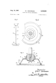
- FIGURE 2 is a longitudinal sectional view showing the lower part of the stand of FIGURE 1 on a larger scale
- FIGURE 3 is a top plan view of the lower part of the stand of FIGURE 2,
- FIGURE 4 is alongituddinal section of the lower part of the stand of a modified structure
- FIGURE 5 is a top plan view of the stand of FIG- URE 4,
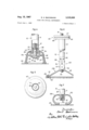
- FIGURE 6 is a side elevation partly in section showing a third modification
- FIGURE 7 is a vertical cross section of the lower part of the stand showing a fourth modification.
- FIGURES 1 to 3 there is illustrated two coaxially mounted profile elements 11 and 12, of which the 'lower profile element telescopically projects into the'upper pipe element 12.
- a clamping device 13 By means of a clamping device 13, the two parts 11 and 12 can be held in any desired extended position, so that the parts 11 and 12 cannot rotate or are slidable relative to each other.
- the parts 11, 12 and 13 together form, in their longitudinal positions, an adjustable leg 10 which at its upper end has, for example, a supporting threaded portion 14 to which an optical instrument, for example a small film camera 15, may be mounted. It is not necessary to further described the foregoing parts.
- the foot 16 On the lower end of the leg 10 there is provided what may be described as a bell-shaped foot 16 which according to FIGURES 2 and 3 is constructed as well be described as follows.
- the foot 16 is in the form a supporting bell 17 which is open at the bottom and has a peripheral bead portion 18 to increase the contact surface on a floor or support surface, as for example, the floor of a room, and this bead portion 18 receives a binding 19 of rubber or a similar substance.
- the peripheral bead or rim 18 and the binding 19 have a rather large diameter as compared with the diameter of the leg 10, so that the foot 16 will possess a relatively wide support-l ing surface to set up and contact the floor or pavement 29.
- the upper part 20 of the supporting bell 17 is formed as a universal joint 21 in the form of a ball member 23 having a screw-threaded socket 24 therein and is connected to a pin 25 connected on the lower end of the leg 11.
- the pin 25 is also provided with screw-threads to mesh with the internal screw-threads 24 in the ball member 23.
- the parts are thus connected to the leg 11 by means of the threaded socket 24 to mesh with the screw-threads 25.
- the socket member 20 has an upper and a lower ring-shaped lip or collar 26 and 27 respectively which exert an elastic force on the outer surface of the ball member 23, so that such lips will prevent foreign matter to penetrate into the seat surface 22 for the part 20.
- the upper lip 26 is also provided for the purpose of preventing the separation of the ball member 23 out of the socket member 22 and also the upper lip 26 creates a frictional contact between the ball 23 and the socket member 20.
- the support bell 17 is provided with at least one small opening 28 to prevent a build-up of a vacuum in the bell 17.
- the foot 16 by means of the rubber frame or binding 19, is placed on the base surface 29 and thus the leg 10 is supported on the surface 29 by means of the foot 16.
- the ring-shaped contact surface is of relatively large diameter between the foot 16 and the floor 29 and the rubber binding 19 will tend to prevent rotation of the foot on the surface 29.
- the camera 15 mounted on the leg 10 by screw-threads at 14, can be rotated together with the leg in a horizontal direction, whereby the ball joint member 23 can rotate in the socket member 20. Due to the weight of the leg 10 and the instrument 15 mounted thereon, if necessary strengthened by human effort downwardly on the instrument 15, there will result a frictional resistance between the ball and socket joint, so that a quick rotation does not take place.
- the optical axis of the camera 15 is thus stabilized in a horizontal direction similar to a tripod support with a panorama head. This was not possible as to known mechanism since in such known structure there was no possibility of rotation in a horizontal plane and no frictional resistance was possible heretofore.
- the ball and socket joint 21 on the foot 16 permits the inclination of the leg 10 to any desired direction relative to the surface 29, as for example, to adjust the optical axis of the camera at an angle downwardly.
- By means of the ball and socket joint 21 it is also possible by vertical positioning of the leg 10, to place the foot on an angular surface as to the entire binding or edge 18 and its rim 19.
- the thin-walled construction of the bell-shaped base 17 has also the advantage to fit such base on uneven surfaces 29 and also in such case upon an undesired rotation of the foot there is no hinderance of the supporting effect for the binding edge rim 19.
- the bell-shaped casing 17 will permit a certain elastic movement of the support in the vertical direction, whereby the optical instrument 15 will be protected against hard knocks when setting up the support on the surface 29.
- the leg part 11 is a tube in which a plug or pin 30 is secured in the end of the tube and this plug is coaxial with the axis of the tube and has a threaded bore 31 therein.
- a threaded end of a screw or bolt 32 meshes with the threads in the bore 31 and with the aid of the screw 32 there is secured a collar-shaped bearing member 33 and a semi-spherical ball member 34, on the end of the tube 11 by means of the plug 30.
- the bearing member 33 is between the semi-ball member 34 and the plug 30.
- the bearing member 33 is surrounded by a rotatable case or socket 35 and is provided with an outwardly projecting flange 36 to prevent axial movement downwardly against the semi-ball member 34.
- a supporting partial globe base member 37 is provided in its top surface with a semispherical depression 39 to receive the semi-ball member 34.
- the member 34 and the semi-socket member 38 form together the ball and socket joint.
- the bell-shaped member 37 is preferably made of a plastic material or from an artificial composition.
- a casing jacket 40 which covers the member 37 and the ball and socket joint 34 and 38, is composed of a rub her or other elastic material, with the jacket 40 having a bell shape and is provided at the bottom part with an inwardly projecting flange 41 which receives the lower edge of the member 37.
- a neck 42 which surrounds the socket 35 and in which the latter is secured.
- An outwardly projecting flange 43 forms part of the socket 35 and this flange 43 is in contact with the upper part of the jacket 40.
- the base member 37 is pressed against the ball member 34 and thereby the member 37 and the ball member 34 will be maintained in contact with each other when the entire stand is lifted.
- the middle point 43 of the partial ball and socket joint 34 and 38 that is the radial middle point for the outer surface of the ball member 34 and the seat surface 39.
- the sliding surfaces for the ball member 34 and the semi-socket member 38 are protected by the jacket 40 against the entry of foreign matter with the bottom 44 of the socket 38 entirely closed.
- FIGURE 4 The use and operation of the structure of FIGURE 4 is essentially the same as the operation of the first modification whereby also the same advantages are achieved as to stabilization for the optical axis as to the optical instrument mounted thereon, such as a camera.
- the ball and socket joint 34 and 38 will provide a free movement and dampened rotary movement for the leg around its longitudinal axis and also dampened swinging motion is possible for the lateral movement of the leg in every direction. During this adjustment the foot portion 116 will remain stationary on the floor 29 or any supporting surface.
- the rubber cover 40 Upon lateral movement of the leg 10 from its vertical axis relative to the surface 29, the rubber cover 40 will attain a certain deformation as to its upper part, but this deformation is held to a minimum since the center point 43' of the ball and socket joint 34 and 38 are practically in a plane in which the upper part of the jacket 40 and the flange 43 of the socket 35 are in contact with each other.
- the jacket 40 Upon the lateral movement of the leg 10 by a stationary foot 116, the jacket 40 will undergo a deformation as to its elastic function which is endeavored to take place to again straighten up the leg 10 or upon lifting of the stand from the surface 29, the foot 116 relative to its leg 10 will return to its coaxial position.
- FIGURE 6 illustrates a third modification of a single leg support and is differentiated from the other two de* scribed constructions thereby that at its upper end of the leg 10, a rotatable connection 45 is provided to which the telescoping leg part 12 is secured to the plate 46 and an upper plate 47 is mounted coaxial with the leg 10.
- the threaded pin 14 receives the optical instrument which seats on the plate 47 and the latter plate is rotatable on the plate 46 and is provided with a friction device 48 of felt or artificial material secured between the plates to thus dampen the rotary movement of the instrument on the plate 47.
- the foot 216 is composed of a comparatively flat supporting bell-shaped member 49 having a bottom peripheral rim 50 with a rubber or similar material cover head 51 thereon. This head 51 will strengthen the support.
- a cross linkage 52 as a universal joint which is composed of the parts 53 which is a projecting lug 54, which is a double fork-shaped member and 55 which is another projecting lug.
- the lower lug 53 is secured by a threaded pin 56 into the upper part of the bell-shaped member 49 whereas the upper link 55 is secured to the telescoping leg part 11 of the leg 10 by any desired securing means.
- the middle double work link 54 of the cross linkage 52 is connected by two pin bolts 57 and 58 at right angles relative to each other to interconnect the lugs 53 and 55. In this way it is possible to adjust the leg relative to the foot 216 in any direction out of the Vertical position but it cannot be rotated.
- the leg and the foot cannot be rotated in any practical manner and in particular the leg 10 is not subject to rotation relative to the surface 29.
- the optical axis of an optical instrument mounted on the plate 47 can only be rotated in a horizontal plane by the relative rotation of the plates 47 and 46 with the friction resistance means 48 between the plates.
- the universal joint 52 permits the adjustment of the leg 10 without lifting the foot 216 from the surface 29. Also, it is possible to mount the foot 216 with its entire rim 51 on any surface other than horizontal and then adjust the leg 10 so that it will be vertical due to the universal joint 52.
- the cone-shaped supporting bell 49 is secured to the universal joint 52 by means of the screw-threaded pin 56 which latter is a part of the universal joint.
- a star-shaped support with at least three radially arranged arms which at their outer ends are provided with a rubber part or the like to form a means to prevent sliding on a floor, road, pavement, and the like.
- the arms of the support means may also be made so that they can be folded together.
- a leg having a foot portion 316 interconnected by a threaded pin 25 and the two parts of the leg 10 as telescoping parts 11 and 12 so that the foot 316 and the leg 10 are not rotatable.
- the foot 316 consists of a single member made of a somewhat stiff but elastic part 60 which is essentially in the form of an open bell and at the bottom having an inwardly directed rim 61.
- the bell can be made of an artificial material, as for example, polyvinylchloride and the upper part of the bell 60 has a central knob 62 directed inwardly and having a screwthread at 63 therin.
- the amount of rigidity of the bell 60 is calculated in such a way that with the flange rim 61 held fast the knob 62 and therewith the foot 10 will possess practically no rotation or swing tendency. Also the bell 60 may be elastically deformable to such an extent that the leg may be bent out of its vertical position to any desired angle with the entire rim 61 of the bell remaining in contact with the surface 29.
- the elastic deformation ability of the bell 60 will permit the foot 316 to be placed on a slanting surface 29 with the entire rim 61 on such surface and still hold the leg 10 in a vertical position. Upon lifting the stand from the surface 29, the foot 316 will assume a coaxial position with the leg due to the elastic property of the foot 316.
- FIGURES 1 to 6 to provide a device of known construction, for dynamic rotary speed dempening between the upper part of the stand and the optical instrument, as for example centrifugal mass or a fluid brake which was only possible for use heretofore with tripods.
- dampening devices are used for swinging a camera slowly for panorama picture-taking, with the optical instrument having such a small stored force that the joint 21 and 34, 38 and 45 of the stand will remain rigid by friction. Quick movement does not permit the dampening device to function and if one sought out a quick movement by large force expenditure, then the rotation in the joint 21 and 34, 38 and 45 will result.
- the mentioned dampening devices can be applied and built into the stand and also combined with the rotary device 45.
- the invention is not necessarily limited to a one leg stand, but can, if desired, also be applied to three-legged stands. It is only thus necessary that one of the legs for the stand shall be provided with the improved foot structure. If the two other legs are to be folded together, the stand can then use a single stand leg. The application of a usual three-legged stand is further possible. In a threelegged stand it is also possible to use a middle column, which according to the invention will have a foot structure, so that the stand, upon folding together the legs and the middle column may be pulled out similar to a single leg stand, all according to the invention.
- a stand for carrying an optical instrument comprising a rigid leg member, connecting means provided at the top of said leg member and adapted to connect said leg member with an optical instrument so that the latter is prevented from angular movement with respect to the top of said leg member about the longitudinal axis thereof, a foot member secured to the lower end of the leg member, said foot member having bearing surface portions for contacting a supporting surface on which the stand is set up, a joint inserted between said leg member and said foot member adapted to allow a tilting movement of said leg member relative to said foot member in any desired direction, and friction means arranged between said supporting surface and said connecting means to brake said optical instrument against unintentional angular movement with respect to the supporting surface about the longitudinal axis of said leg member.
- a stand according to claim 2 wherein said ball member is fixedly secured to the lower end of said leg member through an intermediate shank member, said bearing member being a portion of said foot member and being constituted by a rigid bell-shaped body having a depressed upper end portion, the outer side of which has said hollow spherical bearing surface, and in which said foot member comprises a rubber elastic bell-shaped jacket surrounding said ball member and said bearing member and having an open lower end and an upper end, said jacket having at its lower end an inwardly projecting rim flange engaging a bottom edge of said body, the upper end of said jacket being rotatably connected to said intermediate shank, and said rim flange having said bearing surface portions.
Landscapes
- Engineering & Computer Science (AREA)
- General Engineering & Computer Science (AREA)
- Mechanical Engineering (AREA)
- Accessories Of Cameras (AREA)
Applications Claiming Priority (1)
| Application Number | Priority Date | Filing Date | Title |
|---|---|---|---|
| CH720264A CH430235A (de) | 1964-06-02 | 1964-06-02 | Stativ für optische Instrumente, insbesondere Filmkameras |
Publications (1)
| Publication Number | Publication Date |
|---|---|
| US3335989A true US3335989A (en) | 1967-08-15 |
Family
ID=4321460
Family Applications (1)
| Application Number | Title | Priority Date | Filing Date |
|---|---|---|---|
| US460284A Expired - Lifetime US3335989A (en) | 1964-06-02 | 1965-06-01 | Stand for optical instruments |
Country Status (2)
| Country | Link |
|---|---|
| US (1) | US3335989A (de) |
| CH (1) | CH430235A (de) |
Cited By (18)
| Publication number | Priority date | Publication date | Assignee | Title |
|---|---|---|---|---|
| US3575369A (en) * | 1968-10-28 | 1971-04-20 | Herbert William Tetlow | Support for devices such as cameras, lamps, and the like |
| FR2588637A1 (fr) * | 1985-10-11 | 1987-04-17 | Lambolez Claude | Support portable pour dispositif de prise de vues d'un point eleve au-dessus du sol |
| US4889303A (en) * | 1988-06-24 | 1989-12-26 | Wolf Mitchell E | Flexible arm retainer device |
| US4896804A (en) * | 1988-03-28 | 1990-01-30 | Dearborn James C | Convertible pack frame |
| US5419613A (en) * | 1991-09-30 | 1995-05-30 | Wayne L. Corbell | Chair-mounted platform for adjustably support control devices |
| US6502844B1 (en) * | 2000-08-23 | 2003-01-07 | Stephen M. Winland | Motorcycle kickstand and detent mechanism |
| US20090151605A1 (en) * | 2007-12-13 | 2009-06-18 | Martin Buhler | Table, Particularly a Bar or Bistro Table |
| WO2012170673A1 (en) * | 2011-06-07 | 2012-12-13 | Flir Systems, Inc. | Gimbal system with a translational mount |
| US20130075550A1 (en) * | 2011-09-28 | 2013-03-28 | Wistron Corporation | Supporting assembly for electronic device |
| US8711223B2 (en) | 2011-06-21 | 2014-04-29 | Flir Systems, Inc. | Vehicle-mounted camera stabilized passively by vibration isolators |
| US8844896B2 (en) | 2011-06-07 | 2014-09-30 | Flir Systems, Inc. | Gimbal system with linear mount |
| US9309920B2 (en) | 2013-06-28 | 2016-04-12 | Zhongshan Sirui Photographic Equipment Industry Co., Ltd. | Ball joint orientation device applicable to unipod |
| US20170340813A1 (en) * | 2011-12-29 | 2017-11-30 | Medline Industries, Inc. | Intravenous Pole Base Having Tessellating Elements |
| US10059529B1 (en) * | 2017-07-18 | 2018-08-28 | Regal Beloit America, Inc. | Support pad, system and leg assembly |
| EP3478131A4 (de) * | 2016-07-04 | 2020-03-04 | 3M Innovative Properties Company | Artikelmontagevorrichtung |
| US11813425B2 (en) | 2011-12-29 | 2023-11-14 | Medline Industries, Lp | Apparatus pertaining to a base for a vertical support pole |
| US12004645B2 (en) * | 2022-01-17 | 2024-06-11 | Otto Ganter Gmbh & Co. Kg Normteilefabrik | Articulated adjustable foot comprising support base |
| US12232609B1 (en) * | 2023-10-24 | 2025-02-25 | Furnigami Inc. | Foldable furniture assembly |
Citations (11)
| Publication number | Priority date | Publication date | Assignee | Title |
|---|---|---|---|---|
| US401380A (en) * | 1889-04-16 | Jacob sidney sammons | ||
| US769447A (en) * | 1904-01-18 | 1904-09-06 | Walter Sabin Mckinney | Tripod. |
| US883811A (en) * | 1906-09-01 | 1908-04-07 | Otto Kraus | Telephone-support. |
| US1276666A (en) * | 1917-02-21 | 1918-08-20 | Goodrich Co B F | Ladder-foot. |
| US1337947A (en) * | 1919-07-23 | 1920-04-20 | O'toole William | Signal-post |
| US1463217A (en) * | 1923-07-31 | kristofek | ||
| US1698388A (en) * | 1927-07-25 | 1929-01-08 | Aaron J Brown | Hosiery inspection and display device |
| US1911636A (en) * | 1930-10-16 | 1933-05-30 | meitzler | |
| US2056957A (en) * | 1935-02-18 | 1936-10-13 | Thomas A Colbridge | Chair attachment |
| US2284770A (en) * | 1940-11-30 | 1942-06-02 | Scheuer Clemens | Garment rack |
| US2753586A (en) * | 1954-03-29 | 1956-07-10 | F S Harmon Mfg Co | Caster |
-
1964
- 1964-06-02 CH CH720264A patent/CH430235A/de unknown
-
1965
- 1965-06-01 US US460284A patent/US3335989A/en not_active Expired - Lifetime
Patent Citations (11)
| Publication number | Priority date | Publication date | Assignee | Title |
|---|---|---|---|---|
| US401380A (en) * | 1889-04-16 | Jacob sidney sammons | ||
| US1463217A (en) * | 1923-07-31 | kristofek | ||
| US769447A (en) * | 1904-01-18 | 1904-09-06 | Walter Sabin Mckinney | Tripod. |
| US883811A (en) * | 1906-09-01 | 1908-04-07 | Otto Kraus | Telephone-support. |
| US1276666A (en) * | 1917-02-21 | 1918-08-20 | Goodrich Co B F | Ladder-foot. |
| US1337947A (en) * | 1919-07-23 | 1920-04-20 | O'toole William | Signal-post |
| US1698388A (en) * | 1927-07-25 | 1929-01-08 | Aaron J Brown | Hosiery inspection and display device |
| US1911636A (en) * | 1930-10-16 | 1933-05-30 | meitzler | |
| US2056957A (en) * | 1935-02-18 | 1936-10-13 | Thomas A Colbridge | Chair attachment |
| US2284770A (en) * | 1940-11-30 | 1942-06-02 | Scheuer Clemens | Garment rack |
| US2753586A (en) * | 1954-03-29 | 1956-07-10 | F S Harmon Mfg Co | Caster |
Cited By (20)
| Publication number | Priority date | Publication date | Assignee | Title |
|---|---|---|---|---|
| US3575369A (en) * | 1968-10-28 | 1971-04-20 | Herbert William Tetlow | Support for devices such as cameras, lamps, and the like |
| FR2588637A1 (fr) * | 1985-10-11 | 1987-04-17 | Lambolez Claude | Support portable pour dispositif de prise de vues d'un point eleve au-dessus du sol |
| US4896804A (en) * | 1988-03-28 | 1990-01-30 | Dearborn James C | Convertible pack frame |
| US4889303A (en) * | 1988-06-24 | 1989-12-26 | Wolf Mitchell E | Flexible arm retainer device |
| US5419613A (en) * | 1991-09-30 | 1995-05-30 | Wayne L. Corbell | Chair-mounted platform for adjustably support control devices |
| US6502844B1 (en) * | 2000-08-23 | 2003-01-07 | Stephen M. Winland | Motorcycle kickstand and detent mechanism |
| US20090151605A1 (en) * | 2007-12-13 | 2009-06-18 | Martin Buhler | Table, Particularly a Bar or Bistro Table |
| US8844896B2 (en) | 2011-06-07 | 2014-09-30 | Flir Systems, Inc. | Gimbal system with linear mount |
| WO2012170673A1 (en) * | 2011-06-07 | 2012-12-13 | Flir Systems, Inc. | Gimbal system with a translational mount |
| US8711223B2 (en) | 2011-06-21 | 2014-04-29 | Flir Systems, Inc. | Vehicle-mounted camera stabilized passively by vibration isolators |
| US20130075550A1 (en) * | 2011-09-28 | 2013-03-28 | Wistron Corporation | Supporting assembly for electronic device |
| US8985545B2 (en) * | 2011-09-28 | 2015-03-24 | Wistron Corporation | Supporting assembly for electronic device |
| US20170340813A1 (en) * | 2011-12-29 | 2017-11-30 | Medline Industries, Inc. | Intravenous Pole Base Having Tessellating Elements |
| US11813425B2 (en) | 2011-12-29 | 2023-11-14 | Medline Industries, Lp | Apparatus pertaining to a base for a vertical support pole |
| US9309920B2 (en) | 2013-06-28 | 2016-04-12 | Zhongshan Sirui Photographic Equipment Industry Co., Ltd. | Ball joint orientation device applicable to unipod |
| USRE47931E1 (en) | 2013-06-28 | 2020-04-07 | Guangdong Sirui Optical Co., Ltd. | Ball joint orientation device applicable to unipod |
| EP3478131A4 (de) * | 2016-07-04 | 2020-03-04 | 3M Innovative Properties Company | Artikelmontagevorrichtung |
| US10059529B1 (en) * | 2017-07-18 | 2018-08-28 | Regal Beloit America, Inc. | Support pad, system and leg assembly |
| US12004645B2 (en) * | 2022-01-17 | 2024-06-11 | Otto Ganter Gmbh & Co. Kg Normteilefabrik | Articulated adjustable foot comprising support base |
| US12232609B1 (en) * | 2023-10-24 | 2025-02-25 | Furnigami Inc. | Foldable furniture assembly |
Also Published As
| Publication number | Publication date |
|---|---|
| CH430235A (de) | 1967-02-15 |
Similar Documents
| Publication | Publication Date | Title |
|---|---|---|
| US3335989A (en) | Stand for optical instruments | |
| US20040079849A1 (en) | Support device for a liquid crystal flat screen | |
| US3128982A (en) | Tripod head | |
| US20040079858A1 (en) | Support device for liquid crystal flat screen | |
| US4796508A (en) | Musical instrument support fixture | |
| US1517825A (en) | Tripod | |
| CN206875067U (zh) | 相机支架用相机角度调节机构 | |
| US3300165A (en) | Tripod | |
| US20060272688A1 (en) | Boating seat umbrella assembly | |
| US10801660B1 (en) | Support frame | |
| US4860989A (en) | Quickie mirror | |
| US3091249A (en) | Umbrella with stand | |
| US1406453A (en) | Shock absorber for crutches and the like | |
| US6086207A (en) | Camera leveling head | |
| US20050151037A1 (en) | Self-stabilising support | |
| US2142570A (en) | Support for hair driers or the like | |
| US1883276A (en) | Tripod | |
| CN209130399U (zh) | 摄影用固定支架 | |
| US3716211A (en) | Foldable stand | |
| CN211424038U (zh) | 便携式多角度调节灯架 | |
| US7900286B2 (en) | Support for wall-mounted toilet | |
| ITPD960018U1 (it) | Struttura di supporto perfezionata particolarmente per visori, microscopi, monitor, televisori o simili | |
| US3281590A (en) | Ball joint construction | |
| CN208951560U (zh) | 用于摄像器材的快速锁紧装置和摄像器材组件 | |
| US844670A (en) | Display-fixture. |