US3336023A - Apparatus for manufacturing electric insulators made up of members fitting into one another - Google Patents
Apparatus for manufacturing electric insulators made up of members fitting into one another Download PDFInfo
- Publication number
- US3336023A US3336023A US397183A US39718364A US3336023A US 3336023 A US3336023 A US 3336023A US 397183 A US397183 A US 397183A US 39718364 A US39718364 A US 39718364A US 3336023 A US3336023 A US 3336023A
- Authority
- US
- United States
- Prior art keywords
- members
- columns
- supporting
- rim
- column
- Prior art date
- Legal status (The legal status is an assumption and is not a legal conclusion. Google has not performed a legal analysis and makes no representation as to the accuracy of the status listed.)
- Expired - Lifetime
Links
- 239000012212 insulator Substances 0.000 title description 18
- 238000004519 manufacturing process Methods 0.000 title description 4
- 230000002093 peripheral effect Effects 0.000 claims description 2
- 239000003566 sealing material Substances 0.000 description 3
- 239000000919 ceramic Substances 0.000 description 2
- 239000000463 material Substances 0.000 description 2
- 230000000284 resting effect Effects 0.000 description 2
- 238000007789 sealing Methods 0.000 description 2
- PCHJSUWPFVWCPO-UHFFFAOYSA-N gold Chemical compound [Au] PCHJSUWPFVWCPO-UHFFFAOYSA-N 0.000 description 1
- 239000010931 gold Substances 0.000 description 1
- 229910052737 gold Inorganic materials 0.000 description 1
- 230000037431 insertion Effects 0.000 description 1
- 238000003780 insertion Methods 0.000 description 1
- 239000002184 metal Substances 0.000 description 1
- 229910052751 metal Inorganic materials 0.000 description 1
- 230000035515 penetration Effects 0.000 description 1
- 239000011435 rock Substances 0.000 description 1
Images
Classifications
-
- H—ELECTRICITY
- H01—ELECTRIC ELEMENTS
- H01B—CABLES; CONDUCTORS; INSULATORS; SELECTION OF MATERIALS FOR THEIR CONDUCTIVE, INSULATING OR DIELECTRIC PROPERTIES
- H01B17/00—Insulators or insulating bodies characterised by their form
- H01B17/14—Supporting insulators
-
- B—PERFORMING OPERATIONS; TRANSPORTING
- B28—WORKING CEMENT, CLAY, OR STONE
- B28B—SHAPING CLAY OR OTHER CERAMIC COMPOSITIONS; SHAPING SLAG; SHAPING MIXTURES CONTAINING CEMENTITIOUS MATERIAL, e.g. PLASTER
- B28B1/00—Producing shaped prefabricated articles from the material
- B28B1/002—Producing shaped prefabricated articles from the material assembled from preformed elements
-
- Y—GENERAL TAGGING OF NEW TECHNOLOGICAL DEVELOPMENTS; GENERAL TAGGING OF CROSS-SECTIONAL TECHNOLOGIES SPANNING OVER SEVERAL SECTIONS OF THE IPC; TECHNICAL SUBJECTS COVERED BY FORMER USPC CROSS-REFERENCE ART COLLECTIONS [XRACs] AND DIGESTS
- Y10—TECHNICAL SUBJECTS COVERED BY FORMER USPC
- Y10T—TECHNICAL SUBJECTS COVERED BY FORMER US CLASSIFICATION
- Y10T29/00—Metal working
- Y10T29/51—Plural diverse manufacturing apparatus including means for metal shaping or assembling
- Y10T29/5124—Plural diverse manufacturing apparatus including means for metal shaping or assembling with means to feed work intermittently from one tool station to another
- Y10T29/5127—Blank turret
- Y10T29/513—Stationary work
-
- Y—GENERAL TAGGING OF NEW TECHNOLOGICAL DEVELOPMENTS; GENERAL TAGGING OF CROSS-SECTIONAL TECHNOLOGIES SPANNING OVER SEVERAL SECTIONS OF THE IPC; TECHNICAL SUBJECTS COVERED BY FORMER USPC CROSS-REFERENCE ART COLLECTIONS [XRACs] AND DIGESTS
- Y10—TECHNICAL SUBJECTS COVERED BY FORMER USPC
- Y10T—TECHNICAL SUBJECTS COVERED BY FORMER US CLASSIFICATION
- Y10T29/00—Metal working
- Y10T29/53—Means to assemble or disassemble
- Y10T29/5313—Means to assemble electrical device
- Y10T29/53265—Means to assemble electrical device with work-holder for assembly
Definitions
- An apparatus for making an insulating column which has a plurality of interfitting, sealed members arranged along a vertical axis.
- the apparatus includes columns supporting lugs or fingers each set of which supports the rim of a member so that each member is spaced slightly from adjacent members so that the spaces can be sealed with suitable material, the lugs or fingers on one column being movable to permit lateral removal of the integral insulating column.
- This invention relates to an apparatus for manufacturing electric insulators made up of members fitting into one another.
- These insulators may for example comprise a number of substantially conical members with flared portions.
- the members to be sealed they have to be stacked in such a way that a small crevice or empty space is left between them for the insertion of the sealing material.
- the object of the invention is to provide an apparatus to be used for insulators of difierent calibres.
- a further object is to provide means allowing the complete insulator to be removed easily from the apparatus after sealing.
- the invention consists of an apparatus comprising at least two columns bearing a plurality of projections and arranged in a regular manner around the members so as to support the members individually, means being provided to allow the insulator, after sealing, to be removed perpendicularly to the axes of the columns, passing between two columns.
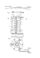
- FIG. 1 represents an elevation, partly in section of an arrangement according to the invention.
- FIG. 2 is a section along line 11-11 in FIG. 1.
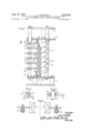
- FIG. 3 is similar to FIG. 1 but shows a different embodiment.
- FIG. 4 is a section along the line IV-IV in FIG. 3 through a column.
- FIG. 5 is a vertical section through a rotatable finger provided on a column
- FIG. 6 shows a horizontal section through an arrangement with two columns with forks.
- the frame 11 of the apparatus has three vertical columns 12, 13 and 14.
- a gauge 15 with projections in the form of lugs 16 is fixed to each column 4 by means of rings 18, the lower rings resting on collars 19 fixed to the columns and adjustable as to height.
- the lugs 16 bear ceramic members 17, in such a way that each member 17 is supported by three lugs 16 belonging respectively to the three gauges 15.
- the vertical distance between the lugs 16 is so selected that a small crevice or empty space is left between the various members 17. If, of course, an insulator comprising mem- 3,336,023 Patented Aug. 15, 1967 bers of different dimensions is going to be assembled, other gauges of appropriate shape will have to be provided.
- the frame member 21 of the insulator is screwed on to a plate 22 which is supported by a ring 23 rigidly joined to the frame 11 of the apparatus.
- the frame member 24 of the insulator is screwed on to a plate 25 carried by a ring 26 resting on adjustable collars 27 supported on the columns 12, 13, 14.
- the frame member 21 is first placed in position after being screwed on to the plate 22.
- Gauges 15 are then selected according to the dimensions of the insulators and are arranged on the columns 12, 13, 14 after the collars 19 have been set at the desired height.
- the three gauges 15 have their lugs 16 directed towards the axis of the machine.
- the members 17 are then arranged on the lugs one after the other. To accomplish this, each member 17 is turned askew so that it fits through the space between lugs 16.
- member 17 is oriented generally as shown in FIGURE 1 and then lowered so that the lugs supportingly engage the member rim.
- the collars 27 are set at the desired height on the columns and the ring 26 is supported on the collars in such a way that the plate 25 and frame member 24 (which need not be metal but may equally well be made of ceramics) are suitably arranged relative to the top member 17.
- the sealing material can be inserted in the crevices between the members before or after these are put in position.
- the asssembly is subjected to vibration in order to settle the sealing material, and it is then dried.
- the insulator is drawn out laterally by turning at least one of the gauges about the axis of its column.
- FIGS. 3 and 4 The arrangement shown in FIGS. 3 and 4 is similar to that just described, but the gauges are here replaced by a series of fingers 28 each supported at the desired height on each column by means of collars 29 and by screws 30, 31.
- One of the columns, for example 12 is rotatable, so that the fingers 28 can be moved away to allow lateral removal of the insulator.
- the penetration and height of the fingers are adjustable, and so the same apparatus can be used in assembling insulators of very difierent dimensions. Instead of having a rotatable column, the fingers may be retracted individually to allow removal of the insulator.
- FIG. 5 illustrates another embodiment, in which the fingers 32 are individually rotatable about a fixed column 33 comprising slots 34, in which lodge clamping screws 35 screwed into collars 36 supporting the fingers.
- Double fingers or forks 39 are fixed to these in an appropriate manner and support the members of the insulator.
- said one column is rotatably mounted on said frame and comprises at least one cylindrical portion, the rim supporting members of said one column comprising a sleeve portion mounted for rotation on said cylindrical portion.
- each rim supporting member comprises two integral horizontally spaced horizontally projecting rim supporting fingers.
Landscapes
- Engineering & Computer Science (AREA)
- Manufacturing & Machinery (AREA)
- Chemical & Material Sciences (AREA)
- Ceramic Engineering (AREA)
- Mechanical Engineering (AREA)
- Insulators (AREA)
- Insulating Bodies (AREA)
Description
Aug. 15, 1967 L. LOCATELLI 3,336,023
APPARATUS FOR MANUFACTURING ELECTRIC INSULATORS MADE UP OF MEMBERS FITTING INTO ONE ANOTHER Filfid Sept. 17, 1964 2 Sheets-Sheet 1 15, 1967 L. LOCATELLI I 3,336,023
APPARATUS FOR MANUFACTURING ELECTRIC INSULATORS MADE v v UP OF MEMBERS FITTING INTO ONE ANOTHER Filed Sept. 17, 1964 2 Sheets-Sheet 2 m V411 EA United States Patent France, assignor to Societe Anonyme,
ABSTRACT OF THE DISCLOSURE An apparatus for making an insulating column which has a plurality of interfitting, sealed members arranged along a vertical axis. The apparatus includes columns supporting lugs or fingers each set of which supports the rim of a member so that each member is spaced slightly from adjacent members so that the spaces can be sealed with suitable material, the lugs or fingers on one column being movable to permit lateral removal of the integral insulating column.
This invention relates to an apparatus for manufacturing electric insulators made up of members fitting into one another.
These insulators may for example comprise a number of substantially conical members with flared portions. For the members to be sealed, they have to be stacked in such a way that a small crevice or empty space is left between them for the insertion of the sealing material.
The object of the invention is to provide an apparatus to be used for insulators of difierent calibres.
A further object is to provide means allowing the complete insulator to be removed easily from the apparatus after sealing.
The invention consists of an apparatus comprising at least two columns bearing a plurality of projections and arranged in a regular manner around the members so as to support the members individually, means being provided to allow the insulator, after sealing, to be removed perpendicularly to the axes of the columns, passing between two columns.
The invention will now be described, by way of example only, with reference to the accompanying drawings. In these:
FIG. 1 represents an elevation, partly in section of an arrangement according to the invention.
FIG. 2 is a section along line 11-11 in FIG. 1.
FIG. 3 is similar to FIG. 1 but shows a different embodiment.
FIG. 4 is a section along the line IV-IV in FIG. 3 through a column.
FIG. 5 is a vertical section through a rotatable finger provided on a column, and
FIG. 6 shows a horizontal section through an arrangement with two columns with forks.
In FIG. 1, the frame 11 of the apparatus has three vertical columns 12, 13 and 14. A gauge 15 with projections in the form of lugs 16 is fixed to each column 4 by means of rings 18, the lower rings resting on collars 19 fixed to the columns and adjustable as to height. The lugs 16 bear ceramic members 17, in such a way that each member 17 is supported by three lugs 16 belonging respectively to the three gauges 15. The vertical distance between the lugs 16 is so selected that a small crevice or empty space is left between the various members 17. If, of course, an insulator comprising mem- 3,336,023 Patented Aug. 15, 1967 bers of different dimensions is going to be assembled, other gauges of appropriate shape will have to be provided.
The frame member 21 of the insulator is screwed on to a plate 22 which is supported by a ring 23 rigidly joined to the frame 11 of the apparatus. Similarly, the frame member 24 of the insulator is screwed on to a plate 25 carried by a ring 26 resting on adjustable collars 27 supported on the columns 12, 13, 14.
To assemble the members 17 and seal the insulator, the frame member 21 is first placed in position after being screwed on to the plate 22. Gauges 15 are then selected according to the dimensions of the insulators and are arranged on the columns 12, 13, 14 after the collars 19 have been set at the desired height.
The three gauges 15 have their lugs 16 directed towards the axis of the machine. The members 17 are then arranged on the lugs one after the other. To accomplish this, each member 17 is turned askew so that it fits through the space between lugs 16. To seat member 17 on the proper set of lugs, member 17 is oriented generally as shown in FIGURE 1 and then lowered so that the lugs supportingly engage the member rim. Finally, the collars 27 are set at the desired height on the columns and the ring 26 is supported on the collars in such a way that the plate 25 and frame member 24 (which need not be metal but may equally well be made of ceramics) are suitably arranged relative to the top member 17.
The sealing material can be inserted in the crevices between the members before or after these are put in position. The asssembly is subjected to vibration in order to settle the sealing material, and it is then dried. When the material has set, the insulator is drawn out laterally by turning at least one of the gauges about the axis of its column.
The arrangement shown in FIGS. 3 and 4 is similar to that just described, but the gauges are here replaced by a series of fingers 28 each supported at the desired height on each column by means of collars 29 and by screws 30, 31. One of the columns, for example 12, is rotatable, so that the fingers 28 can be moved away to allow lateral removal of the insulator. The penetration and height of the fingers are adjustable, and so the same apparatus can be used in assembling insulators of very difierent dimensions. Instead of having a rotatable column, the fingers may be retracted individually to allow removal of the insulator.
FIG. 5 illustrates another embodiment, in which the fingers 32 are individually rotatable about a fixed column 33 comprising slots 34, in which lodge clamping screws 35 screwed into collars 36 supporting the fingers.
Alternatively, only two vertical columns 37 and 38 need be provided, as in FIG. 6. Double fingers or forks 39 are fixed to these in an appropriate manner and support the members of the insulator.
What is claimed is:
1. An apparatus for removably supporting a plurality of interfitting superposed vertically spaced apart insulating articles having a circular peripheral rim, said rims of said articles having a common vertical axis, comprising an article supporting frame, at least two vertical columns secured to said frame, a plurality of vertically spaced apart horizontaly projecting rim supporting members carried by the columns, said n'm supporting members comprising a plurality of sets comprising each at least three members horizontally and circumferentially spaced apart with each member extending generally into the space between the columns for supporting the rim of an article, the rim supporting members carried by at least one of said vertical columns being movably mounted on said column between said rim supporting position and a position permitting the horizontal withdrawal of said articles.
2. An apparatus according to claim 1, in which said one column is rotatably mounted on said frame and comprises at least one cylindrical portion, the rim supporting members of said one column comprising a sleeve portion mounted for rotation on said cylindrical portion.
3. An apparatus according to claim 1, in which the rim supporting members of at least one of said columns are horizontally slidably mounted on said column.
4. An apparatus according to claim 1, in which the rim. supporting members of at least one of said columns are integral with each other and removably mounted on said column.
5. An apparatus according to claim 1, in which each rim supporting member comprises two integral horizontally spaced horizontally projecting rim supporting fingers.
References Cited UNITED STATES PATENTS 355,988 1/1887 Gold 211-176 X 5 1,051,452 1/1913 Rock 2l1174 2,669,013 2/1954 Wilson 269-287 X 2,869,498 1/1959 Whittington 26937 X 3,199,683 8/1965 Graswich.
FOREIGN PATENTS 10 1,352,695 4/1963 France.
ROBERT C. RIORDON, Primary Examiner.
LESTER M. SVVINGLE, Examiner. 1
J. F. MCKEOWN, Assistant Examiner.
Claims (1)
1. AN APPARATUS FOR REMOVABLY SUPPORTING A PLURALITY OF INTERFITTING SUPERPOSED VERTICALLY SPACED APART INSULATING ARTICLES HAVING A CIRCULAR PERIPHERAL RIM, SAID RIMS OF SAID ARTICLES HAVING A COMMON VERTICAL AXIS, COMPRISING AN ARTICLE SUPPORTING FRAME, AT LEAST TWO VERTICAL COLUMNS SECURED TO SAID FRAME, A PLURALITY OF VERTICALLY SPACED APART HORIZONTALLY PROJECTING RIM SUPPORTING MEMBERS CARRIED BY THE COLUMNS, SAID RIM SUPPORTING MEMBERS COMPRISING A PLURALITY OF SETS COMPRISING EACH AT LEAST THREE MEMBERS HORIZONTALLY AND CIRCUMFERENTIALLY SPACED
Applications Claiming Priority (1)
| Application Number | Priority Date | Filing Date | Title |
|---|---|---|---|
| FR947951A FR1383815A (en) | 1963-09-18 | 1963-09-18 | Device for the manufacture of electrical insulators composed of elements which fit into each other |
Publications (1)
| Publication Number | Publication Date |
|---|---|
| US3336023A true US3336023A (en) | 1967-08-15 |
Family
ID=8812653
Family Applications (1)
| Application Number | Title | Priority Date | Filing Date |
|---|---|---|---|
| US397183A Expired - Lifetime US3336023A (en) | 1963-09-18 | 1964-09-17 | Apparatus for manufacturing electric insulators made up of members fitting into one another |
Country Status (4)
| Country | Link |
|---|---|
| US (1) | US3336023A (en) |
| DE (1) | DE1465507A1 (en) |
| FR (1) | FR1383815A (en) |
| GB (1) | GB1007907A (en) |
Citations (6)
| Publication number | Priority date | Publication date | Assignee | Title |
|---|---|---|---|---|
| US355988A (en) * | 1887-01-11 | Stand for displaying goods | ||
| US1051452A (en) * | 1913-01-28 | Milwaukee Heat Generator Company | Folding bakery-rack. | |
| US2669013A (en) * | 1949-08-22 | 1954-02-16 | Wilson John Hart | Precast concrete foundation holding jig |
| US2869498A (en) * | 1957-11-04 | 1959-01-20 | Collins Radio Co | Soldering jig for mechanical filters |
| FR1352695A (en) * | 1963-04-09 | 1964-02-14 | Kon Sphinx Ceramique V H Petru | Support device for supporting saucers, plates or the like, when baking varnish |
| US3199683A (en) * | 1963-12-30 | 1965-08-10 | Dohrmann Hotel Supply Co | Portable and adjustable rack for supporting pans |
-
1963
- 1963-09-18 FR FR947951A patent/FR1383815A/en not_active Expired
-
1964
- 1964-08-17 DE DE19641465507 patent/DE1465507A1/en active Pending
- 1964-09-14 GB GB37462/64A patent/GB1007907A/en not_active Expired
- 1964-09-17 US US397183A patent/US3336023A/en not_active Expired - Lifetime
Patent Citations (6)
| Publication number | Priority date | Publication date | Assignee | Title |
|---|---|---|---|---|
| US355988A (en) * | 1887-01-11 | Stand for displaying goods | ||
| US1051452A (en) * | 1913-01-28 | Milwaukee Heat Generator Company | Folding bakery-rack. | |
| US2669013A (en) * | 1949-08-22 | 1954-02-16 | Wilson John Hart | Precast concrete foundation holding jig |
| US2869498A (en) * | 1957-11-04 | 1959-01-20 | Collins Radio Co | Soldering jig for mechanical filters |
| FR1352695A (en) * | 1963-04-09 | 1964-02-14 | Kon Sphinx Ceramique V H Petru | Support device for supporting saucers, plates or the like, when baking varnish |
| US3199683A (en) * | 1963-12-30 | 1965-08-10 | Dohrmann Hotel Supply Co | Portable and adjustable rack for supporting pans |
Also Published As
| Publication number | Publication date |
|---|---|
| GB1007907A (en) | 1965-10-22 |
| FR1383815A (en) | 1965-01-04 |
| DE1465507A1 (en) | 1969-05-08 |
Similar Documents
| Publication | Publication Date | Title |
|---|---|---|
| JP2017098330A5 (en) | ||
| US3336023A (en) | Apparatus for manufacturing electric insulators made up of members fitting into one another | |
| ES373921A1 (en) | Multistage reactors | |
| ES421121A1 (en) | Basket for handling machine parts | |
| US2372478A (en) | Work holder | |
| GB1239336A (en) | Plates for rectification and gas washing columns | |
| FR2331982A1 (en) | Table with top adjustable for height - has threaded rods in nuts forming articulations for legs and driven by central geared motor unit | |
| CN209652379U (en) | A kind of disk-like accessory heat treatment tooling | |
| CN213866339U (en) | Discharging frame for vacuum heat treatment and discharging frame set thereof | |
| GB794175A (en) | Apparatus for carrying out technical processes by glow discharges | |
| CN206028380U (en) | Solebar rectifies anchor clamps structure | |
| CN105728643A (en) | Wax pattern shelf for investment casting | |
| CN215314846U (en) | Inside and outside plastic processing equipment of leaf spring bimetal bush | |
| ES420715A1 (en) | Perfected system to transfer automatically superposed containers. (Machine-translation by Google Translate, not legally binding) | |
| FR2394389A1 (en) | Press for use with machine tools - has upper platform raised and lowered by power driven threaded support also with traverse | |
| CN214115647U (en) | Layer height adjustable heat treatment tool | |
| CN104889211B (en) | Hydraulic angle pipe bending machine | |
| CN211676154U (en) | Assembled wooden arch cage | |
| BE798230A (en) | SUPPORT ELEMENTS FOR TUBULAR MEMBRANES AND THEIR MANUFACTURING PROCESS | |
| CN108907773B (en) | Frock platform convenient to installation | |
| ES182738U (en) | Container exhibitor for laminar objects. (Machine-translation by Google Translate, not legally binding) | |
| US2146585A (en) | Means for supporting pottery and other goods during firing processes | |
| US2034707A (en) | Apparatus for making one-piece insulators | |
| US674332A (en) | Draw-plate and stand for making seamless gold crowns for teeth. | |
| US3269819A (en) | Method of assembling a glass bead on a wire |