US3336036A - Articulated ski - Google Patents
Articulated ski Download PDFInfo
- Publication number
- US3336036A US3336036A US431398A US43139865A US3336036A US 3336036 A US3336036 A US 3336036A US 431398 A US431398 A US 431398A US 43139865 A US43139865 A US 43139865A US 3336036 A US3336036 A US 3336036A
- Authority
- US
- United States
- Prior art keywords
- ski
- members
- footboard
- bearings
- bar
- Prior art date
- Legal status (The legal status is an assumption and is not a legal conclusion. Google has not performed a legal analysis and makes no representation as to the accuracy of the status listed.)
- Expired - Lifetime
Links
- 239000000543 intermediate Substances 0.000 description 14
- 239000000463 material Substances 0.000 description 3
- XEEYBQQBJWHFJM-UHFFFAOYSA-N Iron Chemical compound [Fe] XEEYBQQBJWHFJM-UHFFFAOYSA-N 0.000 description 2
- 241001532067 Manfreda Species 0.000 description 2
- 230000006978 adaptation Effects 0.000 description 2
- 239000000872 buffer Substances 0.000 description 2
- 239000002184 metal Substances 0.000 description 2
- 229910052751 metal Inorganic materials 0.000 description 2
- 239000012858 resilient material Substances 0.000 description 2
- 230000002411 adverse Effects 0.000 description 1
- PBAYDYUZOSNJGU-UHFFFAOYSA-N chelidonic acid Natural products OC(=O)C1=CC(=O)C=C(C(O)=O)O1 PBAYDYUZOSNJGU-UHFFFAOYSA-N 0.000 description 1
- 239000002131 composite material Substances 0.000 description 1
- 230000000694 effects Effects 0.000 description 1
- 229910052742 iron Inorganic materials 0.000 description 1
- 238000004519 manufacturing process Methods 0.000 description 1
- 239000004033 plastic Substances 0.000 description 1
- 229920003023 plastic Polymers 0.000 description 1
- 238000005096 rolling process Methods 0.000 description 1
- 239000002023 wood Substances 0.000 description 1
Images
Classifications
-
- A—HUMAN NECESSITIES
- A63—SPORTS; GAMES; AMUSEMENTS
- A63C—SKATES; SKIS; ROLLER SKATES; DESIGN OR LAYOUT OF COURTS, RINKS OR THE LIKE
- A63C5/00—Skis or snowboards
- A63C5/02—Skis or snowboards collapsible; divided
-
- A—HUMAN NECESSITIES
- A63—SPORTS; GAMES; AMUSEMENTS
- A63C—SKATES; SKIS; ROLLER SKATES; DESIGN OR LAYOUT OF COURTS, RINKS OR THE LIKE
- A63C5/00—Skis or snowboards
- A63C5/025—Short skis
Definitions
- a ski having a pair of longitudinally spaced ski members connected by a binding support overlying the relatively short ski members, the binding support being increased at intermediate locations along the ski members but at the ends of the binding support, at the ski members for pivoting movement about respective horizontal axes, the pivot is formed by U-shaped or closed-frame arrangements of bars received in bearing members of the ski members and engageable by resilient abutments limiting the pivoting movement.
- the binding support and ski members are attachably connected and provided with locking means for holding them in place.
- a spring means resiliently resists the pivoting movement.
- This invention relates to a ski having a tread portion formed by two short ski members, which are connected by an overlying footboard, which carries the binding.
- ski having a Single, continuous tread enables a fast and versatile advance in the field.
- speed is limited by the great length of the tread, which has a relatively high frictional resistance; the forward sliding is also adversely affected by a certain suction eifect.
- Skis were originally used for a movement in deep snow. This was facilitated by designing them for a small load per unit of area or with long treads. On the one hand, a ski having a much higher load per unit of area and affording a safe guidance would be desirable on modern courses for winter sports as these courses are hard and smooth.
- each of the two short ski members arranged one behind the other has intermediate its length a bearing for the footboard, which is preferably similar to a footstool or bridge and provided, e.g., with angled ends.
- a bearing for the footboard which is preferably similar to a footstool or bridge and provided, e.g., with angled ends.
- this ski has the following advantages:
- the tread which is effective during straight forward skiing in a level field is much smaller than that of a ski having a single, continuous tread so that the resistance to the sliding movement and the suction effect are much reduced.
- a further important improvement is afforded in an embodiment in which the hinge movement of the short ski members relative to the footboard is limited by resilient stops.
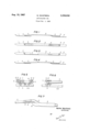
- FIGS. 1, 2 and 3, 4, respectively, are top-plan views and side elevations of embodiments of the invention.
- FIG. 7 is an enlarged view showing a connecting member of a composite footboard.
- the two short ski members 1 and 2 consist e.g., of so-called hardsnow gliders or the like and need not be of the same length. They are provided intermediate their length with bearings 3 and 4, in which the end portions of a footboard are hinged.
- this footboard consists of a rigid frame, which is assembled from tubes or the like and has forward and rear end portions 5, which are angled from the top. This top is provided with a bar or plate 6, to which the binding, not shown, is secured.
- FIGS. 3 and 4 differs from the one described hereinbefore in that the footboard does not consist of a closed frame but of a U-shaped frame, which has end portions hinged to the short ski members at the bearings 3 and 4 and carries the bar 6 for fixing the binding.
- the forward end portion of the substantially horizontal bar 6 may advantageously be curved like a scoop, as is shown in FIG. 4.
- Other embodiments may comprise one or more tubes, rails or the like, which do not extend continuously from the forward bearing 3 to the rear bearing 4 but are secured in any suitable manner to the two ends of the bar 6. These members may be hinged to the ends of the bar 6.
- a relatively strong expanding spring 7 may be provided adjacent to each of the bearings 3 and 4 to urge the end portion 5 of the footboard from the short ski, as is indicated in FIG. 5.
- the ends 5 of the footboard may be connected with interposed leaf springs to the bar 6 for carrying the binding.
- each of the bearings 3 and 4 carried by the short ski members 1 and 2 may be of any suitable known type, they consist preferably of simple journal bearings.
- each of the bearings 3 and 4 may comprise two Z-section bars Sformed with bores for receiving the end portions 5 of the footboard. These bars may be arranged with mirror symmetry and with their lower flanges directed toward each other and secured to the short ski members 1 and 2, e.g., with screws 9.
- Each of the angled or U-shaped end portions 5 of the footboard carries preferably two collars 10, which limit the play of the end portions in the bearings 3 and 4 in the lateral direction of the ski members.
- each bearing 3 or 4 accommodates an expanding spring 7, which is mounted at one end in a bore 11 of a collar 10 and at the other end in the short ski member 1 or 2.
- the turns of the spring 7 may surround the cylindrical core so that they closely engage the core and oppose the hinge movement of the core when the short ski member exceeds a predetermined inclination relative to the horizontal footboard.
- the frame of the footboard is embedded in the bar 6 and the tube 5' is suitably upwardly offset at the point where it emerges from the bar 6.
- the lowermost generatrix of the offset portion of the tube 5' is aligned with the top surface of the bar 6.
- the forward edge of the bar 6- forms suitably a broken or curved line (12 in FIG. 7).
- the offset end of the frame portion 5' may be provided with a socket for connection to a plug.
- the plug connection between the frame members 5' and 5 may be locked by any suitable, known means.
- a U-shaped metal yoke 14 or bent wire may extend through aligned holes 13 in the two frame members fitted together.
- the invention may be embodied in any desired combination of the described features of the ski according to their technical equivalents.
- the movement of the ski according to the invention across irregularities of the course is similar in a sense to the motion of endless track vehicles although the same are not identical or technically equivalent.
- a skier who uses the skis according to the invention can uphold himself much more easily.
- the dangerous sudden deflecting of the skis and hard knocks due to irregularities of the course are prevented to a large extent.
- the direction of movement may be changed at any time, e.g., by a swing.
- the pressure on the footboard is increased by centrifugal force and together with the inclination of the ski may cause portions of the footboard, preferably the bar 6, to be canted in contact with the ground so that they contribute to a reliable regaining of control by the skier when the swing has been completed.
- the skis also adapt themselves well to all irregularities of the ground and a maximum ground adherence is obtained.
- the two short skis may be held by any suitable means so that their treads are parallel to the bar 6 for supporting the binding when they do not contact the ground, e.g., during a field jump.
- These means may comprise a spring 7 as shown in FIG. 5.
- these means may comprise a tension spring, not shown, which is secured at one end to one of the two bars 8 forming the bearing 3 and at the other end to the frame 5 of the footboard.
- a collapsible ski In a collapsible ski according to the invention, specific tip and rear end portions or short ski members 1 and 2 specially particularly suitable for a given purpose, such as downhill, slalom, etc. skiing, may be fitted to the footboard.
- a ski which comprises two ski members, each of which carries on its top intermediate its length a bearing having a horizontal axis which is transverse to the longitudinal direction of the respective ski member, and a binding support disposed above said ski members and hinged to said bearings, said binding support comprising a closed frame and a bar carried by said frame and adapted to have a ski binding secured to it.
- a ski which comprises two ski members, each of which carries on its top intermediate its length a bearing having a horizontal axis which is transverse to the longitudinal direction of the respective ski member, and a binding support disposed above said ski members and hinged to said bearings, said binding support comprising a U-shaped frame having laterally directed limbs hinged to said bearings, and a bar carried by said U-shaped frame and adapted to have a ski binding secured to it.
- a ski which comprises two ski members, each of which carries on its top intermediate its length a bearing having a horizontal axis which is transverse to the longitudinal direction of the respective ski member and a binding support disposed above said ski members and hinged to said bearings, each of said bearings being formed by two Z-section bars extending in the longitudinal direction of the ski member and laterally spaced apart, said bars being arranged with mirror symmetry and having lower flanges directed toward each other and webs formed with laterally aligned bores, and said binding support comprises end portions hinged in said bores.
- a ski which comprises two ski members, each of which carries on its top intermediate its length a bearing having a horizontal axis which is transverse to the longitudinal direction of the respective ski member, and a binding support disposed above said ski members and hinged to said bearings, each of said ski members and its bearing forming a respective assembly, said binding support comprising end portions hinged to said bearings and carrying collars arranged to limit the lateral play of said end portions in said bearings, each of said collars being formed with a bore, said ski further comprising two expanding springs, each of which is mounted on one of said end portions and has one end held in said bore and another end bearing on said assembly.
- a ski which comprises two ski members, each of which carries on its top inter-mediate its length a bearing having a horizontal axis which is transverse to the longitudinal direction of the respective ski member, and a binding support disposed above said ski members and hinged to said bearings, said binding support comprising a bar adapted to have a ski binding secured to it and a frame hinged to said bearings, said frame having an intermediate portion which is countersunk into the top surface of said bar, said frame further having connecting portions extending from said intermediate portion towards said bearings, said connecting portions being upwardly offset from said intermediate portions and having a bottom portion which lies substantially in the same plane as the top surface of said bar.
- a ski which comprises two ski members, each of which carries on its top intermediate its length a bearing having a horizontal axis which is transverse to the longitudinal direction of the respective ski member, and a binding support disposed above said ski members and hinged to said bearings, said binding support comprising a frame hinged to said bearings and a bar adapted to have a ski binding secured to it, said frame comprising a forward part, an intermediate part and a rear part, said bar being secured to said intermediate part, said parts of said frame being detachably connected, and locking means arranged to lock said parts in connected relation.
Landscapes
- Fittings On The Vehicle Exterior For Carrying Loads, And Devices For Holding Or Mounting Articles (AREA)
Applications Claiming Priority (1)
| Application Number | Priority Date | Filing Date | Title |
|---|---|---|---|
| AT128764 | 1964-02-17 |
Publications (1)
| Publication Number | Publication Date |
|---|---|
| US3336036A true US3336036A (en) | 1967-08-15 |
Family
ID=3510615
Family Applications (1)
| Application Number | Title | Priority Date | Filing Date |
|---|---|---|---|
| US431398A Expired - Lifetime US3336036A (en) | 1964-02-17 | 1965-02-09 | Articulated ski |
Country Status (3)
| Country | Link |
|---|---|
| US (1) | US3336036A (de) |
| CH (1) | CH432328A (de) |
| FR (1) | FR1424723A (de) |
Cited By (7)
| Publication number | Priority date | Publication date | Assignee | Title |
|---|---|---|---|---|
| EP0208658A3 (en) * | 1985-05-15 | 1987-09-02 | Alberto Volpato | Snowless skiing device |
| US4725069A (en) * | 1984-11-09 | 1988-02-16 | Marcello Stampacchia | Ski structure |
| EP0412241A1 (de) * | 1989-07-17 | 1991-02-13 | S.B.P. S.r.l. | Zerlegbarer, aus zwei Sektionen bestehenden Ski |
| US5037124A (en) * | 1989-01-18 | 1991-08-06 | S.B.P. S.R.L. | Foldable ski |
| US5083809A (en) * | 1990-02-02 | 1992-01-28 | Marcello Stampacchia | Ski structure |
| WO2001066202A1 (en) * | 2000-03-08 | 2001-09-13 | Odd Gunnar Burmo | Cross-country ski for skiing especially on ice |
| US20090108548A1 (en) * | 2003-03-13 | 2009-04-30 | Fred Jan Dekker | Monoski |
Families Citing this family (3)
| Publication number | Priority date | Publication date | Assignee | Title |
|---|---|---|---|---|
| FR2423243A1 (fr) * | 1978-04-19 | 1979-11-16 | Morys Raymond | Planche a ski |
| DE3633001A1 (de) * | 1986-05-13 | 1987-11-26 | Thomas Reinhardt | Lenkski |
| IT1201736B (it) * | 1986-08-22 | 1989-02-02 | Vittorio Quaggiotti | Sci bipattino con braccio meccanico |
Citations (5)
| Publication number | Priority date | Publication date | Assignee | Title |
|---|---|---|---|---|
| US65396A (en) * | 1867-06-04 | Geoege v | ||
| US1681297A (en) * | 1926-02-04 | 1928-08-21 | Lindroos William Vaino | Snow and ice scooter |
| AT128907B (de) * | 1931-03-16 | 1932-06-25 | Max Haagen | Zerlegbarer Ski. |
| US3030123A (en) * | 1960-03-10 | 1962-04-17 | Theodore A Dworak | Ski mounting apparatus and sled therefor |
| US3260531A (en) * | 1964-01-31 | 1966-07-12 | Johan G F Heuvel | Terrain-conforming and torsionalresponsive skis |
-
1965
- 1965-01-28 CH CH118365A patent/CH432328A/de unknown
- 1965-02-09 US US431398A patent/US3336036A/en not_active Expired - Lifetime
- 1965-02-12 FR FR8249A patent/FR1424723A/fr not_active Expired
Patent Citations (5)
| Publication number | Priority date | Publication date | Assignee | Title |
|---|---|---|---|---|
| US65396A (en) * | 1867-06-04 | Geoege v | ||
| US1681297A (en) * | 1926-02-04 | 1928-08-21 | Lindroos William Vaino | Snow and ice scooter |
| AT128907B (de) * | 1931-03-16 | 1932-06-25 | Max Haagen | Zerlegbarer Ski. |
| US3030123A (en) * | 1960-03-10 | 1962-04-17 | Theodore A Dworak | Ski mounting apparatus and sled therefor |
| US3260531A (en) * | 1964-01-31 | 1966-07-12 | Johan G F Heuvel | Terrain-conforming and torsionalresponsive skis |
Cited By (7)
| Publication number | Priority date | Publication date | Assignee | Title |
|---|---|---|---|---|
| US4725069A (en) * | 1984-11-09 | 1988-02-16 | Marcello Stampacchia | Ski structure |
| EP0208658A3 (en) * | 1985-05-15 | 1987-09-02 | Alberto Volpato | Snowless skiing device |
| US5037124A (en) * | 1989-01-18 | 1991-08-06 | S.B.P. S.R.L. | Foldable ski |
| EP0412241A1 (de) * | 1989-07-17 | 1991-02-13 | S.B.P. S.r.l. | Zerlegbarer, aus zwei Sektionen bestehenden Ski |
| US5083809A (en) * | 1990-02-02 | 1992-01-28 | Marcello Stampacchia | Ski structure |
| WO2001066202A1 (en) * | 2000-03-08 | 2001-09-13 | Odd Gunnar Burmo | Cross-country ski for skiing especially on ice |
| US20090108548A1 (en) * | 2003-03-13 | 2009-04-30 | Fred Jan Dekker | Monoski |
Also Published As
| Publication number | Publication date |
|---|---|
| FR1424723A (fr) | 1966-01-14 |
| CH432328A (de) | 1967-03-15 |
Similar Documents
| Publication | Publication Date | Title |
|---|---|---|
| US4804200A (en) | Sliding device, particularly alpine ski | |
| DE69105113T2 (de) | Skate board für Strassenfahren. | |
| US4305603A (en) | Snow glider | |
| US4225145A (en) | Skateboard apparatus | |
| US3336036A (en) | Articulated ski | |
| US20040262885A1 (en) | Ski with tunnel and enhanced edges | |
| CA2385832A1 (en) | Snow skates | |
| US6357782B1 (en) | Cross-country ski | |
| US3645347A (en) | Guide means for skis | |
| US5782475A (en) | Snowboard binding assembly | |
| JP2004534626A (ja) | カービング小型そり | |
| US3026120A (en) | Ski sled | |
| US6241272B1 (en) | Pair of skis for alpine skiing | |
| US7793969B2 (en) | Ski with suspension | |
| US4487426A (en) | Ski | |
| US3549162A (en) | Ski construction | |
| US5286051A (en) | Alpine ski with a minimum width and specific width/length ratio | |
| CA1167877A (en) | Vehicle for coasting down in a channelshaped roller slide | |
| EP1850924B1 (de) | Stützplatte mit einer verstellbaren asymmetriefunktion für geformte ski | |
| US5944334A (en) | Device for moving over snow | |
| EP1850923B1 (de) | Snowboard für schienen | |
| US4592568A (en) | Ski boot mounting structure for facilitating monoskiing on snow | |
| CA1163661A (en) | Winter sport device with two parallel skids | |
| US3863943A (en) | Ski anti-crossing device | |
| CA1090385A (en) | Twin ski |