US3336626A - Ball applicator assembly - Google Patents
Ball applicator assembly Download PDFInfo
- Publication number
- US3336626A US3336626A US81215A US8121561A US3336626A US 3336626 A US3336626 A US 3336626A US 81215 A US81215 A US 81215A US 8121561 A US8121561 A US 8121561A US 3336626 A US3336626 A US 3336626A
- Authority
- US
- United States
- Prior art keywords
- ball
- applicator
- retainer
- container
- fluid
- Prior art date
- Legal status (The legal status is an assumption and is not a legal conclusion. Google has not performed a legal analysis and makes no representation as to the accuracy of the status listed.)
- Expired - Lifetime
Links
- 238000007789 sealing Methods 0.000 description 67
- 239000012530 fluid Substances 0.000 description 42
- 239000007788 liquid Substances 0.000 description 20
- 230000000994 depressogenic effect Effects 0.000 description 18
- 239000000126 substance Substances 0.000 description 11
- 238000010276 construction Methods 0.000 description 7
- 238000006073 displacement reaction Methods 0.000 description 6
- 239000013536 elastomeric material Substances 0.000 description 4
- 230000001747 exhibiting effect Effects 0.000 description 3
- 239000000463 material Substances 0.000 description 3
- 239000004033 plastic Substances 0.000 description 3
- 229920003023 plastic Polymers 0.000 description 3
- 238000004891 communication Methods 0.000 description 2
- 239000002537 cosmetic Substances 0.000 description 2
- 239000002781 deodorant agent Substances 0.000 description 2
- 239000011521 glass Substances 0.000 description 2
- 239000004698 Polyethylene Substances 0.000 description 1
- 230000001464 adherent effect Effects 0.000 description 1
- 230000000712 assembly Effects 0.000 description 1
- 238000000429 assembly Methods 0.000 description 1
- 238000005452 bending Methods 0.000 description 1
- 239000011248 coating agent Substances 0.000 description 1
- 238000000576 coating method Methods 0.000 description 1
- 230000006835 compression Effects 0.000 description 1
- 238000007906 compression Methods 0.000 description 1
- 239000008278 cosmetic cream Substances 0.000 description 1
- 239000008341 cosmetic lotion Substances 0.000 description 1
- 230000000881 depressing effect Effects 0.000 description 1
- 230000008020 evaporation Effects 0.000 description 1
- 238000001704 evaporation Methods 0.000 description 1
- 230000005484 gravity Effects 0.000 description 1
- 230000002401 inhibitory effect Effects 0.000 description 1
- 239000006210 lotion Substances 0.000 description 1
- 239000002184 metal Substances 0.000 description 1
- 238000004806 packaging method and process Methods 0.000 description 1
- -1 polyethylene Polymers 0.000 description 1
- 229920000573 polyethylene Polymers 0.000 description 1
- 238000009877 rendering Methods 0.000 description 1
- 230000000630 rising effect Effects 0.000 description 1
Images
Classifications
-
- A—HUMAN NECESSITIES
- A45—HAND OR TRAVELLING ARTICLES
- A45D—HAIRDRESSING OR SHAVING EQUIPMENT; EQUIPMENT FOR COSMETICS OR COSMETIC TREATMENTS, e.g. FOR MANICURING OR PEDICURING
- A45D34/00—Containers or accessories specially adapted for handling liquid toiletry or cosmetic substances, e.g. perfumes
- A45D34/04—Appliances specially adapted for applying liquid, e.g. using roller or ball
- A45D34/041—Appliances specially adapted for applying liquid, e.g. using roller or ball using a roller, a disc or a ball
Definitions
- ball-type applicators suitable for transferring a smooth and uniform coating of a liquid or semi-liquid substance from a container to a selected surface such as the human skin have been employed.
- such applicators have basically one functional aspect in common; that is, such applicators characteristically require that the ball applicator be revolved in order to initially transfer the liquid to the exposed or applicating surface of the ball, after which the liquid is transferred from the ball applicator to the skin surface.
- an applicator assembly which permits the ball applicator to initially pump or squirt a measured amount of liquid directly onto the exposed or applicating surface of the ball without necessitating that the applicator be revolved in order to transfer the liquid thereto.
- an object of the present invention to provide an applicator assembly which will function in such manner that it will pump or squirt a measured amount of liquid directly onto the exposed or applicating surface of the applicator ball when said ball is lightly de pressed.
- Another object of the present invention is the provision of a ball-type applicator assembly which may be utilized expeditiously with liquid substances having highly fluid or non-adherent properties rendering such substances unsuitable for utilization with conventional ball-type applicators.
- a further object of the present invention is the provision of an improved fitment for retaining the ball applicator in socketed relationship and which has incorporated therein a reservoir or fluid chamber from which apportioned amounts of fluid may be dispensed.
- a further object of this invention is to provide a retaining fitment which will maintain an applicator of balltype construction in registered alignment with the dispensing opening in a container in such manner that said ball-type applicator may be depressed within said retaining member and immediately pump an apportioned amount of liquid directly onto the exposed surface of the ball.
- a particular object of this invention is to provide a pump-action ball applicator assembly for an inverted-type liquid-dispensing container and, in furtherance of such objective, to provide a resilient socket-type ball retainer for mounting the ball applicator in registration with the dispensing end of the container in such manner that the ball may be resiliently depressed within the retainer and dispel a measured quantity of fluid directly onto the exposed surface of the ball applicator, said retainer also having means incorporated therein for engaging said applicator in sealed relationship when said applicator is in either its depressed or non-depressed position.
- FIG. 1 is an elevational view in central section of a ball-type applicator assembly constructed in accordance with the present invention, and illustrated in its assembled relationship prior to removal of the container closure.
- FIG. 2 is a view similar to FIG. 1, but with the closure removed and showing the functional aspect of the assembly when the liquid is being applied by the ball applicator.
- FIG. 3 is a view taken in the plane 3-3 of FIG. 2, with the ball applicator removed for clarity of illustration.
- FIG. 1 The general arrangement of the elements of this invention, when organized in their assembled relationship, is illustrated in FIG. 1, wherein there is fragmentarily illustrated a fluid dispensing container 10 suitable for packaging liquid cosmetics, lotions, and other similar commercial items.
- the container 10 In the position illustrated, the container 10 is shown, for purposes of comparson with other figures herein, completely inverted from the position which it is intended to ordinarily occupy during storage periods, such as when the container is not being utilized for applicating purposes.
- Threadably secured to the exterior surface of the dispensing end 10a of the container 10 ther is a flat-topped closure 11 which, in addition to isolating the container contents from the ambient atmosphere, has a top surface 11a which functions as a supporting base upon which the container may be supported.
- a ball retainer 12 and a ball applicator 13 which are united in socketed relationship and mounted on the dispensing end 10a of the container.
- the design of the ball applicator 13 and retainer 12 is such that when they are so united a portion of the ball applicator will protrude from the retainer so that it may be depressed by merely pressing it against the surface to which liquid application is desired.
- the assembled ball applicator and retainer fit within the confines of the closure 11 which thereby prevents damage to the assembly and spillage of the container contents such a smight be occasioned by acci dentally upsetting or dropping the container,
- the ball applicator 13 defines a spherical configuration and is of relatively rigid construction so that it will not be susceptible to any appreciable deformation when it is depressed for application of fluid. Suitable materials for this construction are glass, plastic, metal, or other materials having similar characteristics.
- the ball retainer 12 which is fabricated from polyethylene or some other elastomeric material having properties exhibiting similar characteristics of resiliency, softness, and scalability, is constructed with a hollow central pocket 12a which retains a majority portion of the ball applicator in socketed relationship.
- Means for mounting one axial end of the retainer is provided by a radial shoulder 12b, integrally formed on the exterior surface of the retainer and which defines an annular channel designed to fit over the dispensing end ltla of the container 10 in snap-fit relationship.
- annular sealing surface Me which is diametrically smaller than the ball applicator 13.
- a resilient member 12 integrally formed in an upstanding position on the perforate base 12i of the retainer, engages the bottom of the ball applicator 13 and cooperates to maintain the ball applicator in sealing contact with sealing surface 12a.
- the force of gravity aids in urging the ball into sealing contact with sealing surface 12e.
- the resilient member 12 may be shaped in the form of a concave diametrical rib which, as illustrated in FIG.
- a second sealing surface 12g situated at the axially opposite end of pocket 12a from sealing surface 122, is integrally formed within the retainer and shaped to coincide and seal with the surface of the ball applicator 13 to form an inner seal when the applicator is in its depressed position.
- the relative axial spacing of the sealing surfaces 120 and 12g is such that only one of said surfaces is permitted to contact the applicator at any one particular instant. Hence, when a seal is formed at sealing surface 120, the seal at sealing surface 12g will be broken and vice versa.
- the ball retainer 12 defines an annular fluid chamber 12h, surrounding an underside segment of the applicator surface and communicating with the pocket 12a. As illustrated, the major portion of the fluid chamber is disposed axially inward with respect to the center of the applicator 13.
- the closure 11 which is of the screw type, has a generally cup-shaped configuration and may be of plastic, glass, or metallic construction.
- the interior configuration of the closure is such that it generally conforms to the contour of the assembled ball retainer 12 and applicator 13, and accommodates the same therein.
- a circumferential sealing flange 11b is formed within the closure, which engages the shoulder 12b on the ball retainer 12 and limits the extent of axial movement of the closure as it is threaded onto the externally threaded dispensing end a of the container 10, in addition to providing a leak-proof and evaporation inhibiting seal between the closure and ball retainer.
- the present invention incorporates into ball-type applicator assemblies a novel feature which permits an apportioned amount of fluid to be easily applied in a rapid and convenient manner directly onto the surface selected, such as the human skin.
- a pump-action applicator of the type herein described is quite well suited for the application of many substances which are not capable of effective application with conventional-type ball applicators, such as applicators which roll on the substance to be transferred.
- conventional ball applicators are only effective with substances exhibiting relatively viscid characteristics, since adherence of the substance to the surface of the applicator is necessary in order that any substantial transference of the substance may be effected.
- liquid substances having highly fluid and non-sticky properties are not suitable for use with conventional ball-type applicators.
- the pump-type ball applicator assembly comprising the present invention is particularly effective with substances exhibiting highly fluid characteristics and may be advantageously employed in conjunction therewith as well as with the more viscid type substances, such as cosmetic creams, lotions, and various liquid deodorants.
- a ball applicator assembly with an inverted-type fluid cosmetic container having a neck defining an opening in the bottom portion of the container, comprising an applicator ball, an annular ball retainer of resilient elastomeric material having means on one axial end thereof connecting said retainer with said neck and having an axially opposite applicating end, said ball retainer defining a pocket coaxial with said neck receiving the maximum diameter portions of said ball, at least the major portion of the internal surface of said pocket being spaced from the inner side of said ball and defining with said ball an annular fluid chamber disposed between the inner side of said ball and the internal surface of said pocket, said ball retainer also having an inner and an outer annular sealing surface of less diameter than said ball respectively located at each axial end of said pocket and confining said ball in said pocket with a marginal portion of said ball protruding from said applicating end, said annular sealing surfaces being axially spaced sufficiently that said ball can contact only one of such sealing surfaces at a time, said retainer also having formed as an integral part
- a ball applicator package comprising a fluid container having a d spensing opening, an applicator ball disposed in communicating relationship with said opening, an annular ball retainer of elastomeric material on said container surrounding a majority portion of said ball and having an applicating end extending axially outward from said container, said ball retainer defining a pocket receiving the maximum diameter portions of said ball, at least the major portion of the internal surface of said pocket being spaced axially away from the underside of said ball to provide an annular fluid chamber disposed beneath said ball, said ball retainer having an inner and outer annular sealing surface of less diameter than said ball located at opposite axial ends of said pocket and confining said ball within said pocket with a marginal portion of said ball protruding from said applicating end, said annular sealing surfaces being axially spaced sufliciently that said ball can move, axially between said surfaces and contacts only one of said sealing surfaces at a time, said retainer having formed as an integral part thereof a rib of resilient and flexible construction, said
- An applicator assembly for use with a container having a dispensing opening therein, comprising: a spherical applicating member, a resilient and flexible tubular retainer housing said applicating member and having an applicating end and an axially opposite container mounting end, said retainer defining on the interior surface thereof an inner and an outer axially spaced inwardly projecting annular sealing surface and an internal pocket intermediate said sealing surfaces providing a fluid reservoir, the major portion of said fluid reservoir cooperating with the underside of said applicating member to form an annular shape to said reservoir, the major portion of said fluid reservoir also being disposed axially inward with respect to the center of said applicating member and beneath the underside thereof, said sealing surfaces cooperating to loosely confine a medial portion of said applicating member within said pocket for free rotational motion and to support said applicating member so that a marginal portion thereof protrudes axially outward from said retainer, said sea-ling surfaces also being spaced axial.- ly apart a distance precluding concurrent
- a dispensing device comprising a cylindrical shell having a substantilaly flat, circular, resilient, perforated bottom and a top comprising a constricted rim, and a ball confined between said bottom and said rim and pressed against said rim by the resilience of the bottom, said ball having a portion of its surface exposed above said top, and said resilient bottom having in its central portion and rising above the plane thereof an upwardly protruding member engaging said ball and maintaining the resilient bottom under tension by such engagement.
- a dispensing device in which the cylindrical shell is made in one piece of plastic material and in which the constricted rim is sufiiciently resilient to permit the ball to be inserted into the cylindrical shell from the top.
- a dispensing device in which the cylindrical shell is formed with a circumferential rim adapted to engage the upper end of a cylindrical container and is also formed below said rim with a cylindrical portion adapted to make a liquid-tight fit within the neck portion of said cylindrical container.
- a dispensing device wherein the circumferential rim formed on the cylindrical shell is arranged to be engaged from above by an annular shoulder formed on the inner wall of a cylindrical cover applied to the container.
- a ball applicator package comprising a fluid container having a dispensing opening, an applicator ball disposed in said opening, an annular bal-l retainer of elastomeric material on said container surrounding a majority portion of said ball and having an applicating end remote from said container, said ball retainer defining a pocket receiving the maximum diameter portions of said ball, at least the major portion of the internal surface of said pocket being spaced axially away from the underside of said ball to provide an annular fluid chamber disposed beneath said ball, said ball retainer having an inner and outer annular sealing surface of less diameter than said ball located at opposite axial ends of said pocket and confining said ball within said pocket with a marginal portion of said ball protruding from said applicating end, said annular sealing surfaces being axially spaced sufficient'ly that said ball can move axially between said surfaces and contacts only one of said sealing surfaces at a time, said retainer having formed as an integral part thereof a diametrical rib of resilient and flexible construction bridging said dispensing opening and projecting
- An applicator assembly for use with a container having a dispensing opening therein, comprising a spherical applicating member, a resilient and flexible tubular retainer housing said applicating member and having an applicaitng end and an axially opposite container mounting end, said retainer defining on the interior surface thereof an inner and an outer axially spaced inwardly projecting annular sealing surface and an internal pocket intermediate said sealing surfaces providing a fluid reservoir, the major portion of said fluid reservoir cooperating with the underside of said applicating member to form an annular shape to said reservoir, the major portion of said fiuid reservoir also being disposed axially inward with respect to the center of said applicating member and beneath the underside thereof, said sealing surfaces cooperating to loosely confine a medial portion of said applicating member within said pocket for free rotational motion and to support said applicating member so that a marginal portion thereof protrudes axially outward from said retainer, said sealing surfaces also being spaced axially apart a distance precluding concurrent contact
Landscapes
- Closures For Containers (AREA)
- Containers And Packaging Bodies Having A Special Means To Remove Contents (AREA)
Description
Aug. 22, 1967 w. A. SCHAICHI 3,336,626
BALL APPLICATOR ASSEMBLY Filed Jan. 5, 1961 INVENTOR MA /5W4 .f /a/a BY (0. 4 Mr J ATT oRNsY United States Patent 3,336,626 BALL APPLICATOR ASSEMBLY Wilbur A. Schaich, Maumee, Ohio, assignor to Owens- Illinois Inc., a corporation of Ohio Continuation of application Ser. No. 631,622, Dec. 31, 1956. This application Jan. 3, 1961, Ser. No. 81,215
9 Claims. (Cl. 15-572) This application constitutes a continuation of my application Ser. No. 631,622, filed Dec. 31, 1956, and the invention herein relates to an improved ball-type applicator assembly for a liquid dispensing package, wherein the liquid is delivered by a pump-type action to the exposed applicating surface of the ball.
Heretofore, many forms of ball-type applicators suitable for transferring a smooth and uniform coating of a liquid or semi-liquid substance from a container to a selected surface such as the human skin have been employed. However, insofar as is known, such applicators have basically one functional aspect in common; that is, such applicators characteristically require that the ball applicator be revolved in order to initially transfer the liquid to the exposed or applicating surface of the ball, after which the liquid is transferred from the ball applicator to the skin surface. As distinguished from these conventional type applicators, there is presented in this invention an applicator assembly which permits the ball applicator to initially pump or squirt a measured amount of liquid directly onto the exposed or applicating surface of the ball without necessitating that the applicator be revolved in order to transfer the liquid thereto.
Accordingly, it is an object of the present invention to provide an applicator assembly which will function in such manner that it will pump or squirt a measured amount of liquid directly onto the exposed or applicating surface of the applicator ball when said ball is lightly de pressed.
Another object of the present invention is the provision of a ball-type applicator assembly which may be utilized expeditiously with liquid substances having highly fluid or non-adherent properties rendering such substances unsuitable for utilization with conventional ball-type applicators.
A further object of the present invention is the provision of an improved fitment for retaining the ball applicator in socketed relationship and which has incorporated therein a reservoir or fluid chamber from which apportioned amounts of fluid may be dispensed.
A further object of this invention is to provide a retaining fitment which will maintain an applicator of balltype construction in registered alignment with the dispensing opening in a container in such manner that said ball-type applicator may be depressed within said retaining member and immediately pump an apportioned amount of liquid directly onto the exposed surface of the ball.
A particular object of this invention is to provide a pump-action ball applicator assembly for an inverted-type liquid-dispensing container and, in furtherance of such objective, to provide a resilient socket-type ball retainer for mounting the ball applicator in registration with the dispensing end of the container in such manner that the ball may be resiliently depressed within the retainer and dispel a measured quantity of fluid directly onto the exposed surface of the ball applicator, said retainer also having means incorporated therein for engaging said applicator in sealed relationship when said applicator is in either its depressed or non-depressed position.
On the drawings:
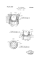
FIG. 1 is an elevational view in central section of a ball-type applicator assembly constructed in accordance with the present invention, and illustrated in its assembled relationship prior to removal of the container closure.
FIG. 2 is a view similar to FIG. 1, but with the closure removed and showing the functional aspect of the assembly when the liquid is being applied by the ball applicator.
FIG. 3 is a view taken in the plane 3-3 of FIG. 2, with the ball applicator removed for clarity of illustration.
The general arrangement of the elements of this invention, when organized in their assembled relationship, is illustrated in FIG. 1, wherein there is fragmentarily illustrated a fluid dispensing container 10 suitable for packaging liquid cosmetics, lotions, and other similar commercial items. In the position illustrated, the container 10 is shown, for purposes of comparson with other figures herein, completely inverted from the position which it is intended to ordinarily occupy during storage periods, such as when the container is not being utilized for applicating purposes. Threadably secured to the exterior surface of the dispensing end 10a of the container 10 ther is a flat-topped closure 11 which, in addition to isolating the container contents from the ambient atmosphere, has a top surface 11a which functions as a supporting base upon which the container may be supported.
Other principal elements comprising this invention are a ball retainer 12 and a ball applicator 13, which are united in socketed relationship and mounted on the dispensing end 10a of the container. The design of the ball applicator 13 and retainer 12 is such that when they are so united a portion of the ball applicator will protrude from the retainer so that it may be depressed by merely pressing it against the surface to which liquid application is desired. Also, the assembled ball applicator and retainer fit within the confines of the closure 11 which thereby prevents damage to the assembly and spillage of the container contents such a smight be occasioned by acci dentally upsetting or dropping the container,
More specifically, the ball applicator 13 defines a spherical configuration and is of relatively rigid construction so that it will not be susceptible to any appreciable deformation when it is depressed for application of fluid. Suitable materials for this construction are glass, plastic, metal, or other materials having similar characteristics. The ball retainer 12, which is fabricated from polyethylene or some other elastomeric material having properties exhibiting similar characteristics of resiliency, softness, and scalability, is constructed with a hollow central pocket 12a which retains a majority portion of the ball applicator in socketed relationship. Means for mounting one axial end of the retainer is provided by a radial shoulder 12b, integrally formed on the exterior surface of the retainer and which defines an annular channel designed to fit over the dispensing end ltla of the container 10 in snap-fit relationship.
Within the ball retainer 12 and restricting the fluid discharge end 1201 thereof, there is formed an annular sealing surface Me, which is diametrically smaller than the ball applicator 13. At this surface 122, the ball applicator 13 and the retainer 12 are normally in sealing contact. A resilient member 12 integrally formed in an upstanding position on the perforate base 12i of the retainer, engages the bottom of the ball applicator 13 and cooperates to maintain the ball applicator in sealing contact with sealing surface 12a. Naturally when the container is inverted, the force of gravity aids in urging the ball into sealing contact with sealing surface 12e. As best shown in FIG. 3, the resilient member 12 may be shaped in the form of a concave diametrical rib which, as illustrated in FIG. 2, yields resiliently when the ball applicator is depressed for applicating purposes. A second sealing surface 12g, situated at the axially opposite end of pocket 12a from sealing surface 122, is integrally formed within the retainer and shaped to coincide and seal with the surface of the ball applicator 13 to form an inner seal when the applicator is in its depressed position. The relative axial spacing of the sealing surfaces 120 and 12g is such that only one of said surfaces is permitted to contact the applicator at any one particular instant. Hence, when a seal is formed at sealing surface 120, the seal at sealing surface 12g will be broken and vice versa. Between the sealing surfaces 121: and 12g, the ball retainer 12 defines an annular fluid chamber 12h, surrounding an underside segment of the applicator surface and communicating with the pocket 12a. As illustrated, the major portion of the fluid chamber is disposed axially inward with respect to the center of the applicator 13.
The closure 11, which is of the screw type, has a generally cup-shaped configuration and may be of plastic, glass, or metallic construction. The interior configuration of the closure is such that it generally conforms to the contour of the assembled ball retainer 12 and applicator 13, and accommodates the same therein. To prevent the closure 11 from contacting and possibly depressing the ball applicator, a circumferential sealing flange 11b is formed within the closure, which engages the shoulder 12b on the ball retainer 12 and limits the extent of axial movement of the closure as it is threaded onto the externally threaded dispensing end a of the container 10, in addition to providing a leak-proof and evaporation inhibiting seal between the closure and ball retainer.
When the container 10 is placed in its customary inverted position, whether during storage or immediately prior to use, a quantity of its fluid contents will flow through the perforate base 121' of the retainer 12. This liquid, naturally, then will flow around the ball applicator 13 past the sealing surface 12g and fill the annular fluid chamber 12h. With the closure removed and the container still in its inverted position, the seal at sealing surface 12e will prevent fluid emergence until the ball applicator is pressed lightly against the surface to which the liquid application is desired. However, when such pressure is applied, it will depress the applicator and the flexible rib member 12 and thereby break the seal at sealing surface 12e and sequentially shift the applicator into sealing engagement with sealing surface 12g. Occasionally at least, it will ordinarily be necessary to apply the containers contents with the applicator 13 in an uppermost position in order to conveniently bring the applicator into contact with surfaces which otherwise are practically inaccessible. For example, underarm deodorants ordinarily and most conveniently are applied with the applicator in an uppermost position in the hand of the user. In such instances, the sealing engagement occurring between the applicator 13 and the sealing surface 12g, as'the applicator is depressed against the surface on which application is desired, will thereby entrap a portion of the containers contents within the fluid chamber 1211 and prevent same from flowing back into the container. Likewise when the applicator is depressed and the container is in an uppermost position, the fluid within the container is prevented from flowing into fluid chamber 12h. Hence, only a measured amount of fluid, corresponding in amount to the fluid'entrapped within the fluid chamber 1211, is available for application. As a further consequence of the shifting of the applicator, a circumferentially larger underside segment of the applicator will be moved into the fluid chamber 1211 and cause the fluid entrapped therein to be compressed and forcibly displaced outward through the annular openings defined between the applicator ball 13 and both respective sealing surfaces 12g and 122. Obviously, however, due to the rapid relative change in size of the respective annular openings, as the applicator ball is depressed, the path of least resistance afforded to the fluid is through the annular opening defined between the applicator 13 and the sealing surface 120. Hence, substantially all of the emergent fluid is expelled through the opening adjacent to sealing surface 12e rather than through the annular opening adjacent to the sealing surface 12g. The compression of the fluid caused by the depression of the applicator ball 13 in turn causes the fluid to issue from the fluid discharge end 12d of the fitment 12 in the form of an annular jet of liquid directed onto the exposed or applicating surface portion of the applicator 13 and, hence, onto the surface against which the applicator has been depressed. Consequently, the applicator, when depressed, functions as a positive displacement pump which facilitates a quick and easy application of only a measured quantity of the liquid. Obviously, such application may be repeated as desired by merely successively inverting the container and manipulating the applicator up and down within the retainer in repetition of the operation described above.
In view of the foregoing, it is manifest that the present invention incorporates into ball-type applicator assemblies a novel feature which permits an apportioned amount of fluid to be easily applied in a rapid and convenient manner directly onto the surface selected, such as the human skin.
A pump-action applicator of the type herein described is quite well suited for the application of many substances which are not capable of effective application with conventional-type ball applicators, such as applicators which roll on the substance to be transferred. Naturally, conventional ball applicators are only effective with substances exhibiting relatively viscid characteristics, since adherence of the substance to the surface of the applicator is necessary in order that any substantial transference of the substance may be effected. Hence, liquid substances having highly fluid and non-sticky properties are not suitable for use with conventional ball-type applicators.
Obviously, the pump-type ball applicator assembly comprising the present invention is particularly effective with substances exhibiting highly fluid characteristics and may be advantageously employed in conjunction therewith as well as with the more viscid type substances, such as cosmetic creams, lotions, and various liquid deodorants.
It will, of course, be understood that various details of construction may be modified through a wide range without departing from the principles of this invention, and it is, therefore, not the purpose to limit the patent granted hereon otherwise than necessitated by the scope of the appended claims.
I claim:
1. The combination of a ball applicator assembly with an inverted-type fluid cosmetic container having a neck defining an opening in the bottom portion of the container, comprising an applicator ball, an annular ball retainer of resilient elastomeric material having means on one axial end thereof connecting said retainer with said neck and having an axially opposite applicating end, said ball retainer defining a pocket coaxial with said neck receiving the maximum diameter portions of said ball, at least the major portion of the internal surface of said pocket being spaced from the inner side of said ball and defining with said ball an annular fluid chamber disposed between the inner side of said ball and the internal surface of said pocket, said ball retainer also having an inner and an outer annular sealing surface of less diameter than said ball respectively located at each axial end of said pocket and confining said ball in said pocket with a marginal portion of said ball protruding from said applicating end, said annular sealing surfaces being axially spaced sufficiently that said ball can contact only one of such sealing surfaces at a time, said retainer also having formed as an integral part thereof a resilient and flexible diametrical web bridging the neck-connecting end thereof, said web having an arched configuration bending towards said pocket and normally biasing said ball resiliently into sealing contact with said outer sealing surface, thereby permitting said annular chamber to fill with fluid when said container is positioned uppermost with respect to said retainer, said web also being sufliciently resilient to accommodate axial displacement of said ball into sealing contact with said inner sealing surface when said ball is forcefully depressed, to thereby pump fluid from said fluid chamber outward through said applicating end.
2. A ball applicator package comprising a fluid container having a d spensing opening, an applicator ball disposed in communicating relationship with said opening, an annular ball retainer of elastomeric material on said container surrounding a majority portion of said ball and having an applicating end extending axially outward from said container, said ball retainer defining a pocket receiving the maximum diameter portions of said ball, at least the major portion of the internal surface of said pocket being spaced axially away from the underside of said ball to provide an annular fluid chamber disposed beneath said ball, said ball retainer having an inner and outer annular sealing surface of less diameter than said ball located at opposite axial ends of said pocket and confining said ball within said pocket with a marginal portion of said ball protruding from said applicating end, said annular sealing surfaces being axially spaced sufliciently that said ball can move, axially between said surfaces and contacts only one of said sealing surfaces at a time, said retainer having formed as an integral part thereof a rib of resilient and flexible construction, said rib having an upwardly projecting portion stressed against the underside of said ball sufficiently that said rib resiliently urges said ball outwardly into sealing contact with said outer sealing surface, said rib also being sufliciently resilient and flexible to accommodate axial displacement of said ball away from said outer sea-ling surface and into sealing contact with said inner sealing surface when the protruding marginal portion of said ball is depressed relative to said retainer.
3. An applicator assembly for use with a container having a dispensing opening therein, comprising: a spherical applicating member, a resilient and flexible tubular retainer housing said applicating member and having an applicating end and an axially opposite container mounting end, said retainer defining on the interior surface thereof an inner and an outer axially spaced inwardly projecting annular sealing surface and an internal pocket intermediate said sealing surfaces providing a fluid reservoir, the major portion of said fluid reservoir cooperating with the underside of said applicating member to form an annular shape to said reservoir, the major portion of said fluid reservoir also being disposed axially inward with respect to the center of said applicating member and beneath the underside thereof, said sealing surfaces cooperating to loosely confine a medial portion of said applicating member within said pocket for free rotational motion and to support said applicating member so that a marginal portion thereof protrudes axially outward from said retainer, said sea-ling surfaces also being spaced axial.- ly apart a distance precluding concurrent contact between same and said applicating member, means on said retainer for engaging said container and disposing said pocket in communication with said dispensing opening, said container mounting end also having as an integral part thereof a resilient and flexible member projecting inwardly and upwardly towards said sealing surfaces and stressed against the underside of said applicating member to bias said applicating member against and into sealing contact with said outer sealing surface, said resilient and flexible member being sufliciently resilient and flexible to accommodate axial displacement of said applicating member away from said outer sealing surface and into sealing contact with said inner sealing surface when the protruding marginal portion of said applicating member is depressed relative to said retainer.
4. A dispensing device comprising a cylindrical shell having a substantilaly flat, circular, resilient, perforated bottom and a top comprising a constricted rim, and a ball confined between said bottom and said rim and pressed against said rim by the resilience of the bottom, said ball having a portion of its surface exposed above said top, and said resilient bottom having in its central portion and rising above the plane thereof an upwardly protruding member engaging said ball and maintaining the resilient bottom under tension by such engagement.
5. A dispensing device according to claim 4, in which the cylindrical shell is made in one piece of plastic material and in which the constricted rim is sufiiciently resilient to permit the ball to be inserted into the cylindrical shell from the top.
6. A dispensing device according to claim 4, in which the cylindrical shell is formed with a circumferential rim adapted to engage the upper end of a cylindrical container and is also formed below said rim with a cylindrical portion adapted to make a liquid-tight fit within the neck portion of said cylindrical container.
7. A dispensing device according to claim 6, wherein the circumferential rim formed on the cylindrical shell is arranged to be engaged from above by an annular shoulder formed on the inner wall of a cylindrical cover applied to the container.
8. A ball applicator package comprising a fluid container having a dispensing opening, an applicator ball disposed in said opening, an annular bal-l retainer of elastomeric material on said container surrounding a majority portion of said ball and having an applicating end remote from said container, said ball retainer defining a pocket receiving the maximum diameter portions of said ball, at least the major portion of the internal surface of said pocket being spaced axially away from the underside of said ball to provide an annular fluid chamber disposed beneath said ball, said ball retainer having an inner and outer annular sealing surface of less diameter than said ball located at opposite axial ends of said pocket and confining said ball within said pocket with a marginal portion of said ball protruding from said applicating end, said annular sealing surfaces being axially spaced sufficient'ly that said ball can move axially between said surfaces and contacts only one of said sealing surfaces at a time, said retainer having formed as an integral part thereof a diametrical rib of resilient and flexible construction bridging said dispensing opening and projecting towards and stressed against the underside of said ball sufficiently that said rib resiliently urges said ball outwardly into sealing contact with said outer sealing surface, said rib also being suificiently resilient and flexible to accommodate axial displacement of said ball away from said outer sealing surface and into sealing contact with said inner sealing surface when the protruding marginal portion of said ball is depressed relative to said retainer.
9. An applicator assembly for use with a container having a dispensing opening therein, comprising a spherical applicating member, a resilient and flexible tubular retainer housing said applicating member and having an applicaitng end and an axially opposite container mounting end, said retainer defining on the interior surface thereof an inner and an outer axially spaced inwardly projecting annular sealing surface and an internal pocket intermediate said sealing surfaces providing a fluid reservoir, the major portion of said fluid reservoir cooperating with the underside of said applicating member to form an annular shape to said reservoir, the major portion of said fiuid reservoir also being disposed axially inward with respect to the center of said applicating member and beneath the underside thereof, said sealing surfaces cooperating to loosely confine a medial portion of said applicating member within said pocket for free rotational motion and to support said applicating member so that a marginal portion thereof protrudes axially outward from said retainer, said sealing surfaces also being spaced axially apart a distance precluding concurrent contact between same and said applicating member, means on said retainer for engaging said container and disposing said pocket in communication with said dispensing opening, said container mounting end also having as an integral part thereof a resilient and flexible diametrical member projecting inwardly and upwardly towards said sealing surfaces and stressed against the underside of said app-licating member to bias said applicating member against and into sealing contact with said outer sealing surface, said diametrical member being sufficiently resilient and flexible to accommodate axial displacement of said applicating member away from said outer sealing surface and into sealing contact with said inner sealing surface when the protruding marginal portion of said applicating member is depressed relative to said retainer.
References Cited UNITED STATES PATENTS 2/1911 Wlliams 222501 X 2/1915 Bussey 222501 X 4/1938 Krannak 15-572 10/1955 Ackerman 15572 6/1956 Thomas 15-572 X 2/1958 Whitney 15-572 FOREIGN PATENTS 4/1921 France.
ROBERT W. MICHELL, Primary Examiner.
15 S. JAMES, Examiner.
Claims (1)
- 4. A DISPENSING DEVICE COMPRISING A CYLINDRICAL SHELL HAVING A SUBSTANTIALLY FLAT, CIRCULAR RESILIENT, PERFORATED BOTTOM AND A TOP COMPRISING A CONSTRICTED RIM, AND A BALL CONFINED BETWEEN SAID BOTTOM AND SAID RIM AND PRESSED AGAINST SAID RIM BY THE RESILIENCE OF THE BOTTOM, SAID BALL HAVING A PORTION OF ITS SURFACE EXPOSED ABOVE SAID TOP, AND SAID RESILIENT BOTTOM HAVING IN ITS CENTRAL PORTION AND RISING ABOVE THE PLANE THEREOF AN UPWARDLY PROTRUDING MEMBER ENGAGING SAID BALL AND MAINTAINING THE RESILIENT BOTTOM UNDER TENSION BY SUCH ENGAGEMENT.
Priority Applications (1)
| Application Number | Priority Date | Filing Date | Title |
|---|---|---|---|
| US81215A US3336626A (en) | 1961-01-03 | 1961-01-03 | Ball applicator assembly |
Applications Claiming Priority (1)
| Application Number | Priority Date | Filing Date | Title |
|---|---|---|---|
| US81215A US3336626A (en) | 1961-01-03 | 1961-01-03 | Ball applicator assembly |
Publications (1)
| Publication Number | Publication Date |
|---|---|
| US3336626A true US3336626A (en) | 1967-08-22 |
Family
ID=22162799
Family Applications (1)
| Application Number | Title | Priority Date | Filing Date |
|---|---|---|---|
| US81215A Expired - Lifetime US3336626A (en) | 1961-01-03 | 1961-01-03 | Ball applicator assembly |
Country Status (1)
| Country | Link |
|---|---|
| US (1) | US3336626A (en) |
Cited By (6)
| Publication number | Priority date | Publication date | Assignee | Title |
|---|---|---|---|---|
| EP0712592A1 (en) * | 1994-11-18 | 1996-05-22 | The Procter & Gamble Company | A roll-on applicator |
| US5897267A (en) * | 1994-11-18 | 1999-04-27 | The Procter & Gamble Company | Roll-on applicator |
| US6179505B1 (en) * | 1995-06-20 | 2001-01-30 | The Procter & Gamble Company | Venting roll-on applicator |
| FR2953107A1 (en) * | 2009-12-02 | 2011-06-03 | Thomas Eugene Joseph Diezinger | DEVICE FOR APPLICATION OF A FLUID |
| EP3388360A4 (en) * | 2015-12-10 | 2019-08-21 | Kobayashi Pharmaceutical Co., Ltd. | Chemical solution supply apparatus and chemical solution supply implement |
| US11020275B1 (en) * | 2016-08-17 | 2021-06-01 | Tom Barrows | Protective goggles |
Citations (7)
| Publication number | Priority date | Publication date | Assignee | Title |
|---|---|---|---|---|
| US984630A (en) * | 1909-11-08 | 1911-02-21 | Patrick J Walsh | Liquid-soap container. |
| US1129449A (en) * | 1914-01-31 | 1915-02-23 | Alexander P Browne | Dispenser for liquid soap and the like. |
| FR522572A (en) * | 1920-08-06 | 1921-08-02 | Felix Giraud | Box in the form of a bar of soap or other dispensing liquid soap or any solutions by friction |
| US2113695A (en) * | 1937-09-17 | 1938-04-12 | Steven J Krannak | Tube closure |
| US2719997A (en) * | 1952-07-11 | 1955-10-11 | Ackerman Dolletta May | Dispenser and applicator |
| US2749566A (en) * | 1952-09-04 | 1956-06-12 | Bristol Myers Co | Dispenser |
| US2823403A (en) * | 1956-04-23 | 1958-02-18 | Owensillinois Glass Company | Ball and socket plastic fitment |
-
1961
- 1961-01-03 US US81215A patent/US3336626A/en not_active Expired - Lifetime
Patent Citations (7)
| Publication number | Priority date | Publication date | Assignee | Title |
|---|---|---|---|---|
| US984630A (en) * | 1909-11-08 | 1911-02-21 | Patrick J Walsh | Liquid-soap container. |
| US1129449A (en) * | 1914-01-31 | 1915-02-23 | Alexander P Browne | Dispenser for liquid soap and the like. |
| FR522572A (en) * | 1920-08-06 | 1921-08-02 | Felix Giraud | Box in the form of a bar of soap or other dispensing liquid soap or any solutions by friction |
| US2113695A (en) * | 1937-09-17 | 1938-04-12 | Steven J Krannak | Tube closure |
| US2719997A (en) * | 1952-07-11 | 1955-10-11 | Ackerman Dolletta May | Dispenser and applicator |
| US2749566A (en) * | 1952-09-04 | 1956-06-12 | Bristol Myers Co | Dispenser |
| US2823403A (en) * | 1956-04-23 | 1958-02-18 | Owensillinois Glass Company | Ball and socket plastic fitment |
Cited By (12)
| Publication number | Priority date | Publication date | Assignee | Title |
|---|---|---|---|---|
| EP0712592A1 (en) * | 1994-11-18 | 1996-05-22 | The Procter & Gamble Company | A roll-on applicator |
| WO1996015694A1 (en) * | 1994-11-18 | 1996-05-30 | The Procter & Gamble Company | A roll-on applicator |
| US5897267A (en) * | 1994-11-18 | 1999-04-27 | The Procter & Gamble Company | Roll-on applicator |
| US6179505B1 (en) * | 1995-06-20 | 2001-01-30 | The Procter & Gamble Company | Venting roll-on applicator |
| FR2953107A1 (en) * | 2009-12-02 | 2011-06-03 | Thomas Eugene Joseph Diezinger | DEVICE FOR APPLICATION OF A FLUID |
| FR2953109A1 (en) * | 2009-12-02 | 2011-06-03 | Thomas Eugene Joseph Diezinger | DEVICE FOR APPLICATION OF A FLUID |
| WO2011067500A1 (en) * | 2009-12-02 | 2011-06-09 | Diezinger Thomas Eugene Joseph | Fluid application device |
| US9730501B2 (en) | 2009-12-02 | 2017-08-15 | Thomas Eugene Joseph Diezinger | Fluid application device |
| EP3388360A4 (en) * | 2015-12-10 | 2019-08-21 | Kobayashi Pharmaceutical Co., Ltd. | Chemical solution supply apparatus and chemical solution supply implement |
| US10932542B2 (en) | 2015-12-10 | 2021-03-02 | Kobayashi Pharmaceutical Co., Ltd. | Chemical solution supply apparatus and chemical solution supply implement |
| US11122881B2 (en) | 2015-12-10 | 2021-09-21 | Kobayashi Pharmaceutical Co., Ltd. | Chemical solution supply apparatus and chemical solution supply implement |
| US11020275B1 (en) * | 2016-08-17 | 2021-06-01 | Tom Barrows | Protective goggles |
Similar Documents
| Publication | Publication Date | Title |
|---|---|---|
| US2749566A (en) | Dispenser | |
| US2823403A (en) | Ball and socket plastic fitment | |
| US2968826A (en) | Fluid dispenser with ball applicator | |
| US5810495A (en) | Narrow line applicator | |
| US6309124B1 (en) | Device for dispensing and applying a product | |
| US5967685A (en) | Assembly for applying a fluid or a solid product | |
| CA1182431A (en) | Liquid dispensing pump arrangement with selective stroke restriction | |
| US6776549B2 (en) | Device and method for applying a product | |
| US2853728A (en) | Dispenser-applicator for liquid containers | |
| US3111703A (en) | Deodorant device | |
| US2923957A (en) | gentile | |
| US2998616A (en) | Ball applicator dispensers | |
| US6773193B2 (en) | Packaging and applicator device including an element forming an intermediate reservoir | |
| US20190357656A1 (en) | Receptacle for mixing of different materials | |
| US7168598B2 (en) | Device for dispensing a product | |
| WO2020027987A1 (en) | Dropper dispensers and methods of using the same | |
| US3336626A (en) | Ball applicator assembly | |
| US3378330A (en) | Fluid dispenser | |
| US10906055B2 (en) | Device for packaging and dispensing a product comprising a moveable piston | |
| US2858558A (en) | Combination bottle closure and ball applicator | |
| US2910712A (en) | Ball-type dispensing package | |
| US3083397A (en) | Roller applicator supporting means | |
| EP0100204B1 (en) | Applicator for creams and viscous liquids | |
| US2937391A (en) | Ball-type applicator assembly | |
| US3062415A (en) | Improved dispenser delivering chamber |