US3336783A - Device for manufacturing a pre-impregnated oil-filled cable having a metal sheath - Google Patents
Device for manufacturing a pre-impregnated oil-filled cable having a metal sheath Download PDFInfo
- Publication number
- US3336783A US3336783A US392475A US39247564A US3336783A US 3336783 A US3336783 A US 3336783A US 392475 A US392475 A US 392475A US 39247564 A US39247564 A US 39247564A US 3336783 A US3336783 A US 3336783A
- Authority
- US
- United States
- Prior art keywords
- oil
- cable
- tube
- sheath
- metal sheath
- Prior art date
- Legal status (The legal status is an assumption and is not a legal conclusion. Google has not performed a legal analysis and makes no representation as to the accuracy of the status listed.)
- Expired - Lifetime
Links
Images
Classifications
-
- B—PERFORMING OPERATIONS; TRANSPORTING
- B21—MECHANICAL METAL-WORKING WITHOUT ESSENTIALLY REMOVING MATERIAL; PUNCHING METAL
- B21C—MANUFACTURE OF METAL SHEETS, WIRE, RODS, TUBES, PROFILES OR LIKE SEMI-MANUFACTURED PRODUCTS OTHERWISE THAN BY ROLLING; AUXILIARY OPERATIONS USED IN CONNECTION WITH METAL-WORKING WITHOUT ESSENTIALLY REMOVING MATERIAL
- B21C23/00—Extruding metal; Impact extrusion
- B21C23/22—Making metal-coated products; Making products from two or more metals
- B21C23/24—Covering indefinite lengths of metal or non-metal material with a metal coating
- B21C23/26—Applying metal coats to cables, e.g. to insulated electric cables
-
- H—ELECTRICITY
- H01—ELECTRIC ELEMENTS
- H01B—CABLES; CONDUCTORS; INSULATORS; SELECTION OF MATERIALS FOR THEIR CONDUCTIVE, INSULATING OR DIELECTRIC PROPERTIES
- H01B13/00—Apparatus or processes specially adapted for manufacturing conductors or cables
- H01B13/06—Insulating conductors or cables
- H01B13/14—Insulating conductors or cables by extrusion
-
- H—ELECTRICITY
- H01—ELECTRIC ELEMENTS
- H01B—CABLES; CONDUCTORS; INSULATORS; SELECTION OF MATERIALS FOR THEIR CONDUCTIVE, INSULATING OR DIELECTRIC PROPERTIES
- H01B13/00—Apparatus or processes specially adapted for manufacturing conductors or cables
- H01B13/22—Sheathing; Armouring; Screening; Applying other protective layers
- H01B13/24—Sheathing; Armouring; Screening; Applying other protective layers by extrusion
- H01B13/245—Sheathing; Armouring; Screening; Applying other protective layers by extrusion of metal layers
-
- H—ELECTRICITY
- H01—ELECTRIC ELEMENTS
- H01B—CABLES; CONDUCTORS; INSULATORS; SELECTION OF MATERIALS FOR THEIR CONDUCTIVE, INSULATING OR DIELECTRIC PROPERTIES
- H01B13/00—Apparatus or processes specially adapted for manufacturing conductors or cables
- H01B13/30—Drying; Impregnating
Definitions
- the present invention relates to the extrusion of a metal sheath, in particular an aluminium sheath, onto cables of the oil-filled type which are impregnated with a thin oil before the sheath is applied.
- the inner diameter of the sheath during the extrusion, has a larger diameter than the impregnated cable, as the sheath after the extrusion is to be corrugated or drawn through a shrinking die to a diameter corresponding to the impregnated cable.
- This drawing or corrugation may be performed in a manner known per se in a separate operation after the sheath is applied, or it may be done in the same operation.
- the sheath is made of a metal which requires a higher sheathing temperature, e.g. of aluminium
- the oil will be decomposed if it comes in touch with the extruding die or the hot metal sheath.
- the die and the sheath leaving the extruder have a temperature of about 500 C., and this temperature is too high for the thin oil used.
- a tube into the extruder, said tube encompassing the cable and being so long that it shields against the hot parts of the extruder and the metal sheath.
- This tube is at one end attached to the tube which connects the extruder with the impregnating vessel and at the other end provided with a gasket, the object of which is to make a tight connection between the shielding tube and the metal sheath, at the place where the sheath is cooled down to an acceptable temperature.
- the object of the present invention is to provide a solution to this problem whereby the said difficulties are overcome.
- a double walled tube is inserted into the extruding tool.
- the inner wall of the tube is vacuum tight and connected directly or indirectly to the tube which connects the impregnating vessel with the extruder and is a continuation of this tube.
- the outer wall of the double walled tube which must be inserted so far into the extruder that the end is well out of the hot zone of the aluminium sheath which is produced, is provided with holes in the end of the tube.
- the intermediate space between the walls in the double walled tube is connected by means of a vacuum tight tube to an oil reservoir or a degassing device, e.g., by means of an oil pump, a cooler and a filter.
- a degassing device e.g., by means of an oil pump, a cooler and a filter.
- the oil is forced to flow along the cable through the holes in the double walled tube and into the intermediate space in the double walled tube.
- the opposite flow of oil thereby provided partly protects the cable against excessive temperature and partly brings with it some of the oil which may have been subjected to the excessive temperature, so that this oil is prevented from entering the cable.
- This oil which is flowing in the opposite direction is called the flushing oil and may upon leaving the intermediate space in the double walled tube be accumulated in a reservoir, e.g.
- the oil may be used againif necessary after being filtered and cleaned in a suitable way and if necessary clay treated or treated in other ways before it is used again. However, it may alternatively be brought directly back to the impregnating vessel or to some other parts of the system without any extra treatment if special precautions are taken.
- the sheath will, due to the friction between the sheath and the oil, have a tendency to bring some of the oil vapor into the cable, and this is undesirable even for small amounts.
- the flushing process will, however, reduce this tendency to a minimum and instead make sure that this part of the oil vapor is brought with the flushing oil into the intermediate space in the double walled tube.
- the flushing oil may also be led to a de-gasingdevice which removes the oil vapor not being condensed into the oil, whereupon the oil is led back to the impregnating vessel or to a vessel for de-gasified oil ready for use for impregnation.
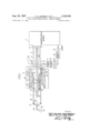
- FIGURE 1 shows schematically an extruding system in which the flushing oil is led back to the impregnating vessel
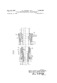
- FIGURE 2 shows an embodiment of the double walled tube which may be adapted to fit a Schloemann aluminium press
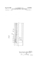
- FIGURE 3 shows another embodiment of the double walled tube.
- An impregnating vessel 1 is connected with an extruder 2, by means of a tube 3 and vacuum tight gaskets 4 and 5.
- a double walled tube 6, must, due to limited space, have thin walls and should preferably consist of stainless steel or some other mechanical solid material, which does not act as a catalyst for oxidation of the oil or otherwise cause deterioration of the oil.
- Its inner wall is; hydraulically connected to the tube 3, between the vessel 1 and the extruder 2, in such a way that the oil 7, which comes from the vessel 1, passes via the tube 3 to the inside of the tube 6.
- the oil 7 may further flow through the intermediate space 9 in the double walled tube 6, this intermediate space being hydraulically connected to an oil conducting tube 10, which may be in direct connection with an accumulating reservoir for the oil, or as shown in FIG. 1, with the impregnating vessel 1.
- an oil conducting tube 10 which may be in direct connection with an accumulating reservoir for the oil, or as shown in FIG. 1, with the impregnating vessel 1.
- the de-gasifier 14 As the de-gasifier 14 is vacuum operated, it is necessary to arrange a pump before the vessel 1, as the latter has to be under pressure. This pump 15 is therefore providing the circulation of oil. It may sometimes also be advantageous to arrange a pump 11 before the filter in order to increase the velocity.
- the oil may naturally also be led via a filter 12, a cooler 13 and so on to a separate reservoir or to the tube 3 instead of the impregnating vessel 1.
- the outlet of the vessel 1 at flange 4 is provided with a specially designed valve which is not shown in the figure. This valve is closed during the evacuation.
- the system is suificiently evacuated, it is filled with oil from the vessel 1. It may, however, also be filled with degasified oil from any other suitable oil reservoir than the impregnating vessel.
- the cable 21 is pulled by means of a metal wire 22 or such, connected to the sleeve 17 on the metal sheath 16, as the extrusionof the sheath is started.
- the double walled tube with holes for oil circulation must be adapted for the different types of extruders for which it is to be used.
- FIG. 2 there is shown in detail a device which e.g. may be used for the so-called Schloemann aluminium press.
- This extruder is originally provided with a removable cooling shield 27 having a double threaded track 28 for cooling water.
- the double walled tube 6 is connected to the cooling shield, and to a single walled tube 29 which preferably consists of stainless steel, the intermediate space 9 in the double walled tube 6 communicating with the intermediate space between the tube 29 and the cooling shield 27.
- the gaskets 30, 31 and 32 are made vacuum tight of suitable heat resistant gasket material.
- the gasket 33 between the tubes 29 and 3 does not have to be vacuum tight.
- FIG. 3 is shown another embodiment of the double walled tube 6 where the end of this tube is provided with a flange 34, the purpose of which is to reduce the intermediate space 35 between the sheath 16 and the double walled tube 6 at its end, in order to increase the velocity of oil at this place.
- the oil 7 will thereby more easily bring possible oil vapor 25, which otherwise might follow the sheath 16 due to friction into the holes 8 in the double walled tube 6.
- a device for manufacturing a pre-impregnated oilfilled cable comprising an inner cable, a metal sheath surrounding said cable and having an inner diameter larger than the outer diameter of the cable core, an extruding die surrounding a portion of said cable and adapted to extrude metal around said cable as the cable is moved along an axial path to form said metal sheath, a heat protecting tube disposed within the extruding die and coaxial therewith between the metal sheath and the cable, a source of oil, said tube having a first channel permitting said oil to flow around said cable within said tube in the direction of the movement of the cable and a second channel permitting the oil to flow in an opposite direction Within said tube to provide cooling of the cable core and the extruding die and the hot metal sheath.
- said tube comprises inner and outer concentric walls with an intermediate space therebetween, holes disposed in said outer wall so that said oil is forced to flow from around said table into said intermediate space in a flow direction opposite to the direction in which the cable is moved, an oil reservoir, and means conducting said oil from said intermediate space into said reservoir 3.
- said holes in the outer wall of said tube consist of transverse slots.
- a device wherein said holes in the outer wall of said tube are arranged near the end of the tube, so that the oil flows through the holes at a position spaced from the extruding die before it enters said intermediate space and flows past said die.
- a device wherein the end of said tube includes a flange which reduces the cross section for oil flow between the tube and the sheath in order to increase the oil velocity at said end.
- a device wherein the end portion of said tube is double walled while the rest is single walled, the extruding die having a cooling shield between the die and single walled portion and having an end intermediate space between the cooling shield and the single walled tube portion communicating with the intermediate space in the double walled end of the tube on one side and with said reservoir on the other side.
- a device further comprising a filter and a cooler disposed between said tube and reservoir for cleaning and cooling said oil.
- a device further comprising a de-gasifier coupled between said cooler and said reservan.
- a device including means returning said oil to said tube from said reservoir so that the oil flows in a closed system.
- a device wherein said reser- UNITED STATES PATENTS 1/1963 Priaroggia 72-268 2/1964 Linnerz 72268 CHARLES W. LANHAM, Primary Examiner.
Landscapes
- Engineering & Computer Science (AREA)
- Manufacturing & Machinery (AREA)
- Mechanical Engineering (AREA)
- Manufacturing Of Electric Cables (AREA)
- Extrusion Moulding Of Plastics Or The Like (AREA)
Applications Claiming Priority (1)
| Application Number | Priority Date | Filing Date | Title |
|---|---|---|---|
| NO15083563 | 1963-11-15 |
Publications (1)
| Publication Number | Publication Date |
|---|---|
| US3336783A true US3336783A (en) | 1967-08-22 |
Family
ID=19908880
Family Applications (1)
| Application Number | Title | Priority Date | Filing Date |
|---|---|---|---|
| US392475A Expired - Lifetime US3336783A (en) | 1963-11-15 | 1964-08-27 | Device for manufacturing a pre-impregnated oil-filled cable having a metal sheath |
Country Status (6)
| Country | Link |
|---|---|
| US (1) | US3336783A (de) |
| CH (1) | CH433472A (de) |
| DE (1) | DE1590563A1 (de) |
| ES (1) | ES305944A1 (de) |
| GB (1) | GB1075014A (de) |
| SE (1) | SE312159B (de) |
Cited By (2)
| Publication number | Priority date | Publication date | Assignee | Title |
|---|---|---|---|---|
| US4564347A (en) * | 1983-04-12 | 1986-01-14 | Babcock Wire Equipment Limited | Continuous extrusion apparatus |
| CN115674629A (zh) * | 2022-11-01 | 2023-02-03 | 湖北力生电缆有限公司 | 一种高一致性电缆护套制造用挤塑机 |
Citations (2)
| Publication number | Priority date | Publication date | Assignee | Title |
|---|---|---|---|---|
| US3073441A (en) * | 1960-05-11 | 1963-01-15 | Pirelli | Apparatus for hot-sheathing electric cables with tubular metal sheaths |
| US3120305A (en) * | 1958-05-17 | 1964-02-04 | Schloemann Ag | Cooling of cable sheaths, particularly aluminium cable sheaths |
-
1964
- 1964-08-27 US US392475A patent/US3336783A/en not_active Expired - Lifetime
- 1964-10-08 SE SE12075/64A patent/SE312159B/xx unknown
- 1964-11-11 CH CH1455064A patent/CH433472A/de unknown
- 1964-11-12 ES ES0305944A patent/ES305944A1/es not_active Expired
- 1964-11-13 GB GB46301/64A patent/GB1075014A/en not_active Expired
- 1964-11-14 DE DE19641590563 patent/DE1590563A1/de active Pending
Patent Citations (2)
| Publication number | Priority date | Publication date | Assignee | Title |
|---|---|---|---|---|
| US3120305A (en) * | 1958-05-17 | 1964-02-04 | Schloemann Ag | Cooling of cable sheaths, particularly aluminium cable sheaths |
| US3073441A (en) * | 1960-05-11 | 1963-01-15 | Pirelli | Apparatus for hot-sheathing electric cables with tubular metal sheaths |
Cited By (2)
| Publication number | Priority date | Publication date | Assignee | Title |
|---|---|---|---|---|
| US4564347A (en) * | 1983-04-12 | 1986-01-14 | Babcock Wire Equipment Limited | Continuous extrusion apparatus |
| CN115674629A (zh) * | 2022-11-01 | 2023-02-03 | 湖北力生电缆有限公司 | 一种高一致性电缆护套制造用挤塑机 |
Also Published As
| Publication number | Publication date |
|---|---|
| CH433472A (de) | 1967-04-15 |
| DE1590563A1 (de) | 1969-10-02 |
| SE312159B (de) | 1969-07-07 |
| GB1075014A (en) | 1967-07-12 |
| ES305944A1 (es) | 1965-05-01 |
Similar Documents
| Publication | Publication Date | Title |
|---|---|---|
| US3054142A (en) | Extrusion of thermosetting polymeric materials | |
| DE1936609A1 (de) | Isolierter Behaelter | |
| US3336783A (en) | Device for manufacturing a pre-impregnated oil-filled cable having a metal sheath | |
| HU214020B (en) | Sizing tool | |
| KR940006949A (ko) | 광섬유상에 탄소코팅을 제공하는 장치 | |
| US3952568A (en) | Vacuum processing of rod, wire or strip material | |
| US4058671A (en) | Electrical penetration assembly | |
| US3997318A (en) | Plunger for forming hollow glass articles | |
| EP0445944B1 (de) | Verbesserung hinsichtlich Kalander und Presswalzen | |
| EP0202953A2 (de) | Vorrichtung zum kontinuierlichen Strangpressen | |
| US2981409A (en) | Sealing device for lead press | |
| US2545728A (en) | Method of forming glass tubing | |
| US4236573A (en) | High-temperature gas exit from a pre-stressed pressure container | |
| US2789314A (en) | Apparatus for vulcanizing an extruded sheath on a continuous core | |
| US2759087A (en) | Laminated metal liner for induction coils | |
| GB1568409A (en) | Method of forming extruded thermoplastics conduit around electrical cable | |
| US2642622A (en) | Continuous vulcanizing apparatus | |
| US1442213A (en) | Metal-drawing apparatus and method | |
| US3487506A (en) | Extruder for sheathing cable cores | |
| US4512737A (en) | Hot zone arrangement for use in a vacuum furnace | |
| US3540467A (en) | Gas-cooled stopper rod assembly | |
| SU378301A1 (ru) | Прецизионный металлорежущий станок | |
| JPS59178121A (ja) | 伸線加工機用ワイヤ冷却装置 | |
| US3053976A (en) | Methods and apparatus for sheathing | |
| US4620433A (en) | Wire cooling apparatus for a wire drawing machine |