US3336828A - Blind nuts - Google Patents
Blind nuts Download PDFInfo
- Publication number
- US3336828A US3336828A US474219A US47421965A US3336828A US 3336828 A US3336828 A US 3336828A US 474219 A US474219 A US 474219A US 47421965 A US47421965 A US 47421965A US 3336828 A US3336828 A US 3336828A
- Authority
- US
- United States
- Prior art keywords
- cage
- arms
- nut
- opening
- notches
- Prior art date
- Legal status (The legal status is an assumption and is not a legal conclusion. Google has not performed a legal analysis and makes no representation as to the accuracy of the status listed.)
- Expired - Lifetime
Links
- 230000001154 acute effect Effects 0.000 claims description 5
- 101100008050 Caenorhabditis elegans cut-6 gene Proteins 0.000 description 5
- 238000005452 bending Methods 0.000 description 5
- 238000010276 construction Methods 0.000 description 2
- 239000000463 material Substances 0.000 description 2
- 239000002184 metal Substances 0.000 description 2
- 230000006835 compression Effects 0.000 description 1
- 238000007906 compression Methods 0.000 description 1
- 230000008602 contraction Effects 0.000 description 1
- 238000003780 insertion Methods 0.000 description 1
- 230000037431 insertion Effects 0.000 description 1
- 238000000034 method Methods 0.000 description 1
Images
Classifications
-
- F—MECHANICAL ENGINEERING; LIGHTING; HEATING; WEAPONS; BLASTING
- F16—ENGINEERING ELEMENTS AND UNITS; GENERAL MEASURES FOR PRODUCING AND MAINTAINING EFFECTIVE FUNCTIONING OF MACHINES OR INSTALLATIONS; THERMAL INSULATION IN GENERAL
- F16B—DEVICES FOR FASTENING OR SECURING CONSTRUCTIONAL ELEMENTS OR MACHINE PARTS TOGETHER, e.g. NAILS, BOLTS, CIRCLIPS, CLAMPS, CLIPS OR WEDGES; JOINTS OR JOINTING
- F16B37/00—Nuts or like thread-engaging members
- F16B37/04—Devices for fastening nuts to surfaces, e.g. sheets, plates
- F16B37/06—Devices for fastening nuts to surfaces, e.g. sheets, plates by means of welding or riveting
- F16B37/062—Devices for fastening nuts to surfaces, e.g. sheets, plates by means of welding or riveting by means of riveting
- F16B37/065—Devices for fastening nuts to surfaces, e.g. sheets, plates by means of welding or riveting by means of riveting by deforming the material of the nut
- F16B37/067—Devices for fastening nuts to surfaces, e.g. sheets, plates by means of welding or riveting by means of riveting by deforming the material of the nut the material of the nut being deformed by a threaded member generating axial movement of the threaded part of the nut, e.g. blind rivet type
-
- Y—GENERAL TAGGING OF NEW TECHNOLOGICAL DEVELOPMENTS; GENERAL TAGGING OF CROSS-SECTIONAL TECHNOLOGIES SPANNING OVER SEVERAL SECTIONS OF THE IPC; TECHNICAL SUBJECTS COVERED BY FORMER USPC CROSS-REFERENCE ART COLLECTIONS [XRACs] AND DIGESTS
- Y10—TECHNICAL SUBJECTS COVERED BY FORMER USPC
- Y10S—TECHNICAL SUBJECTS COVERED BY FORMER USPC CROSS-REFERENCE ART COLLECTIONS [XRACs] AND DIGESTS
- Y10S411/00—Expanded, threaded, driven, headed, tool-deformed, or locked-threaded fastener
- Y10S411/913—Self-expanding anchor
-
- Y—GENERAL TAGGING OF NEW TECHNOLOGICAL DEVELOPMENTS; GENERAL TAGGING OF CROSS-SECTIONAL TECHNOLOGIES SPANNING OVER SEVERAL SECTIONS OF THE IPC; TECHNICAL SUBJECTS COVERED BY FORMER USPC CROSS-REFERENCE ART COLLECTIONS [XRACs] AND DIGESTS
- Y10—TECHNICAL SUBJECTS COVERED BY FORMER USPC
- Y10S—TECHNICAL SUBJECTS COVERED BY FORMER USPC CROSS-REFERENCE ART COLLECTIONS [XRACs] AND DIGESTS
- Y10S411/00—Expanded, threaded, driven, headed, tool-deformed, or locked-threaded fastener
- Y10S411/955—Locked bolthead or nut
- Y10S411/965—Locked bolthead or nut with retainer
- Y10S411/969—Deformable retainer
Definitions
- blind nuts are devices enabling screws to be fastened to panels or other thin structures from one side only, for use when the other side of the panel is inaccessible.
- blind nuts should be capable of being inserted through an opening in the panel from the accessible side after which a bolt or screw can be screwed into the blind nut for example for fastening some other element to the panel.
- the problem is to prevent the blind nut from turning during the screwing operation and an object of the present invention is to provide an improved means for preventing this turning.
- a blind nut comprises a threaded member and an abutment, a cage holding the threaded member from the abutment, the cage having arms for insertion with the threaded member into an opening until the abutment engages the surroundings of the opening and including acute angle notches in the edges of the arms for engaging the edge of the surrounding of the opening with a wedging action for preventing the nut from turning when a bolt is threaded into the threaded member.
- the nut When the screw is inserted and tightening starts, the nut will move with the screw until the edge of the panel surrounding the opening engages the acute angle notches and becomes wedged therein after which the nut is prevented from turning.
- This construction has the advantage that when the blind nut is inserted through the opening in the panel no further operation is necessary to secure it before the screw is inserted; that the holding of the nut does not rely on the use of interengaging teeth or the like on the nut and panel; and that the construction can be very simple.
- the cage and its arms at least can be formed by pressing and bending from sheet material.
- the threaded member which could be a conventional nut could be welded or otherwise secured to the cage in this case.
- the notches may be formed by cutting from the sides of the arms during the blanking operation or could be formed by bending outwards the parts of the cage on either side of a single cut.
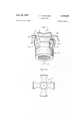
- FIGURE 1 is a view in perspective of this embodiment
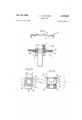
- FIGURE 2a is a plan view of the sheet metal blank cut and folded to form the cage of this embodiment
- FIGURE 2b is a view in section across the axis of the cage of FIGURE 2a;
- FIGURE 3 shows partly in section and partly in elevation the blind nut of this embodiment cooperating with a bolt in the assembly of a panel on a supporting panel;
- FIGURE 4a is a view in section of this embodiment.
- FIGURE 4b is a plan view of this embodiment.
- the blind nut is seen to comprise a cage 1 attached to, and co-axial with, a threaded portion 2.
- the cage 1 is made from a cut and folded sheet metal blank F (as can be seen from FIGURE 2a) and comprises four arms or branches 3 arranged in axial symmetry about a central annular portion 16, which encircles an opening 1a.
- the threaded portion 2 is comparable with a normal nut.
- FIGURE 4a The method of attaching the cage 1 to the threaded portion 2 is shown in FIGURE 4a.
- An annular projection 2a and an associated annular groove 2b are formed on the inner surface of the threaded portion 2.
- the central annular portion 1b of the cage 1 is formed with an axially and outwardly projecting rim. This rim is engaged with the annular groove 2b, thereby causing the annular projection 2a to enter the opening 1a.
- the projection 2a is then distorted to lock the rim of the portion 1b in the annular groove 2b.
- Each of the arms or branches 3 of the cage 1 is bent inwardly and away from the threaded portion 2, part way towards a position parallel to the central axis of the blind nut.
- Each arm 3 has two further bends. The first of these, at 3a, occurs about a third of the way along the length of each arm; here the outer part of the arm is bent towards the central axis.
- the second bend, at 3b, occurs about two thirds of the way along each arm; here the bend is away from the central axis to which the extremity 4 of each arm is now nearly at right angles.
- This extremity 4 thus forms a flange, and the cage 1 takes on a barrel-shaped structure, the bends 3a occurring at its widest transverse dimension. This is best seen in FIG- URE 1.
- a cut 6 is made into the middle portion of each arm 3 from one side towards the line of the bend 3b.
- An acute V-notch 5 is formed by bending apart the edges of this cut 6.
- the edge adjacent the flange 4 is bent in a direction away from the threaded portion 2 to form a tooth 4b, while the other edge of the cut is bent in the opposite direction to form a second tooth 6a.
- the blind nut is passed, threaded portion 2 first, through a circular hole of suitable dimensions in the work from the accessible to the inaccessible surface.
- the arms 3 permit this by resilient contraction towards the central axis.
- the flanges 4 prevent it from falling into the 'hole while the expanded girth of the cage prevents it from falling out.
- the bolt is then screwed into the nut 2. As the bolt is turned, say in the sense R in FIGURE 1, the nut 2 and its cage will tend to turn in the same sense.
- each arm 3 in which the cut 6 is made will depend on the turning direction R.
- the invention is not limited to the single embodiment described but extends to all the variants corresponding to its principle.
- the threaded portion 2 and the cage 1 might be constructed as an integral component.
- a blind nut adapted to be inserted into an opening in a thin structure, one face of which is not readily accessible, said nut comprising a deformable cage having a generally barrel-like shape, a threaded member fixed at the bottom of said cage and axially aligned with said cage, said cage including a plurality of flat resilient arms, arranged in axial symmetry, fixed to said threaded memher and extending upwardly therefrom, said arms having upper ends, remote from said threaded member, outwardly bent about a bend line to form transverse flanges, said flanges being adapted to lie upon the accessible face of said structure when said nut is inserted into said opening in the structure, said arms having acute angle notches beneath said flanges, said notches having upper edges disposed along said bend lines and lower edges extending upwardly and transversely from one lateral edge of said arm towards said bend lines, said notches opening externally of said arms and widening in the direction in which a bolt is threadably advanced in said threaded member such
- a blind nut as claimed in claim 1 wherein said upper edges of said notches are bent inwardly and said lower edge is bent outwardly to form a tooth.
- a blind nut as claimed in claim 1 wherein said arms are bowed outwardly to form an expanded girth acting as creasing lines when a bolt is threaded in said threaded member.
Landscapes
- Engineering & Computer Science (AREA)
- General Engineering & Computer Science (AREA)
- Mechanical Engineering (AREA)
- Dowels (AREA)
- Bolts, Nuts, And Washers (AREA)
Applications Claiming Priority (1)
| Application Number | Priority Date | Filing Date | Title |
|---|---|---|---|
| FR984244A FR1411180A (fr) | 1964-08-05 | 1964-08-05 | Perfectionnements aux écrous aveugles et analogues |
Publications (1)
| Publication Number | Publication Date |
|---|---|
| US3336828A true US3336828A (en) | 1967-08-22 |
Family
ID=8836129
Family Applications (1)
| Application Number | Title | Priority Date | Filing Date |
|---|---|---|---|
| US474219A Expired - Lifetime US3336828A (en) | 1964-08-05 | 1965-07-21 | Blind nuts |
Country Status (7)
| Country | Link |
|---|---|
| US (1) | US3336828A (fr) |
| BE (1) | BE666979A (fr) |
| CH (1) | CH428329A (fr) |
| DE (1) | DE1450908A1 (fr) |
| FR (1) | FR1411180A (fr) |
| GB (1) | GB1074754A (fr) |
| NL (1) | NL6510224A (fr) |
Cited By (8)
| Publication number | Priority date | Publication date | Assignee | Title |
|---|---|---|---|---|
| US3778755A (en) * | 1972-11-06 | 1973-12-11 | Berg Electronics Inc | Self-staking wire grip terminal |
| US5727761A (en) * | 1995-09-29 | 1998-03-17 | Ho; Hsin Chien | Circuit board locating device |
| US5906346A (en) * | 1996-11-15 | 1999-05-25 | Enlight Corporation | Baseplate holder |
| US20030068198A1 (en) * | 2001-10-09 | 2003-04-10 | Tyco Electronics Corporation | Quick-attach automotive antenna mounting assembly |
| US20050105987A1 (en) * | 2003-11-17 | 2005-05-19 | Giugliano Michael A. | Spring fastener with highly improved lever/angle pulling force |
| US7088297B2 (en) | 2003-11-25 | 2006-08-08 | Harada Industry Co., Ltd. | Vehicle roof antenna attachment |
| US20160375840A1 (en) * | 2006-11-29 | 2016-12-29 | Termax Corporation | Spring Fastener |
| US11174890B1 (en) * | 2020-05-08 | 2021-11-16 | Caterpillar Inc. | Fastener retaining component |
Families Citing this family (5)
| Publication number | Priority date | Publication date | Assignee | Title |
|---|---|---|---|---|
| DE3208461A1 (de) * | 1982-03-09 | 1983-09-15 | Hilti AG, 9494 Schaan | "duebel zum befestigen von gegenstaenden an bauteilen" |
| US4595325A (en) * | 1984-09-28 | 1986-06-17 | Eaton Corporation | Self-locking prevailing torque fastener |
| DE10223747B4 (de) * | 2002-05-28 | 2007-09-06 | Dieter Dr. Grotmann | Klemmstück zur Montage eines Bauteils an einer Platte |
| DE102007017908A1 (de) * | 2007-04-17 | 2008-10-23 | Fischerwerke Gmbh & Co. Kg | Befestigungselement und Befestigungsanordnung |
| TR2022004036A2 (tr) * | 2022-03-17 | 2022-04-21 | Kenan Coskun | Yeni̇ bi̇r bağlanti si̇stemi̇ |
Citations (11)
| Publication number | Priority date | Publication date | Assignee | Title |
|---|---|---|---|---|
| US2000241A (en) * | 1931-05-27 | 1935-05-07 | New Brunswick Electric Supply | Electric fixture-supporting and connecting device |
| US2017421A (en) * | 1934-04-16 | 1935-10-15 | Newhall Henry B Corp | Crimp nut |
| USRE22543E (en) * | 1936-10-14 | 1944-09-05 | Fastening device | |
| US2406415A (en) * | 1943-07-22 | 1946-08-27 | Tinnerman Products Inc | Fastening device |
| FR917384A (fr) * | 1939-12-29 | 1947-01-06 | Tinnerman Products Inc | Système d'attache |
| US2539172A (en) * | 1948-01-16 | 1951-01-23 | Tinnerman Products Inc | Fastening device |
| DE832221C (de) * | 1948-10-02 | 1952-02-21 | Josef Banholzer Dipl Ing | Schraubbefestigung an Gehaeusewandungen o. dgl. |
| GB732556A (en) * | 1951-07-19 | 1955-06-29 | United Carr Fastener Corp | Improvements in and relating to fastener devices for assembly in apertured panels orlike supports |
| US2762252A (en) * | 1955-04-27 | 1956-09-11 | Diamond Expansion Bolt Co | One-piece collapsible sheet metal bolt anchor |
| FR1285367A (fr) * | 1961-01-11 | 1962-02-23 | Anciens Etablissements Bac | Perfectionnements aux écrous-aveugles |
| US3091425A (en) * | 1961-04-27 | 1963-05-28 | Holophane Co Inc | Snap nut fastener |
-
1964
- 1964-08-05 FR FR984244A patent/FR1411180A/fr not_active Expired
-
1965
- 1965-07-15 BE BE666979A patent/BE666979A/xx unknown
- 1965-07-21 US US474219A patent/US3336828A/en not_active Expired - Lifetime
- 1965-07-22 CH CH1027865A patent/CH428329A/fr unknown
- 1965-07-31 DE DE19651450908 patent/DE1450908A1/de active Pending
- 1965-08-04 GB GB33388/65A patent/GB1074754A/en not_active Expired
- 1965-08-05 NL NL6510224A patent/NL6510224A/xx unknown
Patent Citations (11)
| Publication number | Priority date | Publication date | Assignee | Title |
|---|---|---|---|---|
| US2000241A (en) * | 1931-05-27 | 1935-05-07 | New Brunswick Electric Supply | Electric fixture-supporting and connecting device |
| US2017421A (en) * | 1934-04-16 | 1935-10-15 | Newhall Henry B Corp | Crimp nut |
| USRE22543E (en) * | 1936-10-14 | 1944-09-05 | Fastening device | |
| FR917384A (fr) * | 1939-12-29 | 1947-01-06 | Tinnerman Products Inc | Système d'attache |
| US2406415A (en) * | 1943-07-22 | 1946-08-27 | Tinnerman Products Inc | Fastening device |
| US2539172A (en) * | 1948-01-16 | 1951-01-23 | Tinnerman Products Inc | Fastening device |
| DE832221C (de) * | 1948-10-02 | 1952-02-21 | Josef Banholzer Dipl Ing | Schraubbefestigung an Gehaeusewandungen o. dgl. |
| GB732556A (en) * | 1951-07-19 | 1955-06-29 | United Carr Fastener Corp | Improvements in and relating to fastener devices for assembly in apertured panels orlike supports |
| US2762252A (en) * | 1955-04-27 | 1956-09-11 | Diamond Expansion Bolt Co | One-piece collapsible sheet metal bolt anchor |
| FR1285367A (fr) * | 1961-01-11 | 1962-02-23 | Anciens Etablissements Bac | Perfectionnements aux écrous-aveugles |
| US3091425A (en) * | 1961-04-27 | 1963-05-28 | Holophane Co Inc | Snap nut fastener |
Cited By (13)
| Publication number | Priority date | Publication date | Assignee | Title |
|---|---|---|---|---|
| US3778755A (en) * | 1972-11-06 | 1973-12-11 | Berg Electronics Inc | Self-staking wire grip terminal |
| US5727761A (en) * | 1995-09-29 | 1998-03-17 | Ho; Hsin Chien | Circuit board locating device |
| US5906346A (en) * | 1996-11-15 | 1999-05-25 | Enlight Corporation | Baseplate holder |
| US20060110214A1 (en) * | 2001-10-09 | 2006-05-25 | Kozlovski A D | Quick-attach automotive antenna mounting assembly |
| US7004666B2 (en) * | 2001-10-09 | 2006-02-28 | Tyco Electronics Corporation | Quick-attach automotive antenna mounting assembly |
| US20030068198A1 (en) * | 2001-10-09 | 2003-04-10 | Tyco Electronics Corporation | Quick-attach automotive antenna mounting assembly |
| US7212168B2 (en) | 2001-10-09 | 2007-05-01 | Tyco Electronics Corporation | Quick-attach automotive antenna mounting assembly |
| US20050105987A1 (en) * | 2003-11-17 | 2005-05-19 | Giugliano Michael A. | Spring fastener with highly improved lever/angle pulling force |
| US7188392B2 (en) * | 2003-11-17 | 2007-03-13 | Termax Corporation | Spring fastener with highly improved lever/angle pulling force |
| US7088297B2 (en) | 2003-11-25 | 2006-08-08 | Harada Industry Co., Ltd. | Vehicle roof antenna attachment |
| US20160375840A1 (en) * | 2006-11-29 | 2016-12-29 | Termax Corporation | Spring Fastener |
| US11603050B2 (en) * | 2006-11-29 | 2023-03-14 | Termax Company | Spring fastener |
| US11174890B1 (en) * | 2020-05-08 | 2021-11-16 | Caterpillar Inc. | Fastener retaining component |
Also Published As
| Publication number | Publication date |
|---|---|
| CH428329A (fr) | 1967-01-15 |
| GB1074754A (en) | 1967-07-05 |
| FR1411180A (fr) | 1965-09-17 |
| NL6510224A (fr) | 1966-02-07 |
| DE1450908A1 (de) | 1969-04-17 |
| BE666979A (fr) | 1966-01-17 |
Similar Documents
| Publication | Publication Date | Title |
|---|---|---|
| US3336828A (en) | Blind nuts | |
| DE853226C (de) | Bolzen- und Mutterbefestigung | |
| US3437119A (en) | Captive bolt unit | |
| US3014563A (en) | Anchor assembly | |
| US3783922A (en) | Blind mounting fastener | |
| US3090203A (en) | Support plate for an anchoring device | |
| US3008368A (en) | Adjusting device | |
| US2779375A (en) | Split washer having one helical margin and one planar margin adapted to be secured to threaded fastener | |
| US2917267A (en) | Clamp | |
| US3373789A (en) | Sheet metal nut with resilient cage | |
| US3025897A (en) | Snap-in type caged nuts | |
| US2239797A (en) | Spring fastener | |
| US3314465A (en) | Nut with resilient arms | |
| JPS5926611A (ja) | ボルト継手連結装置 | |
| US3901122A (en) | Variable expansion compression nut and bolt assembly | |
| US2367659A (en) | Nut | |
| US2010519A (en) | Sheet metal nut structure | |
| US2144895A (en) | Toggle bolt | |
| US2156002A (en) | Fastening device | |
| US2391989A (en) | Threaded locking device | |
| US3614144A (en) | Expansion clip and method of installing recessed fixtures with such clips | |
| US3008554A (en) | Nut and retainer for workpieces with non-parallel faces | |
| US3137197A (en) | Sheet metal nut with sealer escapement ports | |
| US2564645A (en) | Locking nut | |
| US3388627A (en) | Composite fastener assembly |