US3336911A - Supercharged diesel engine and method of operating the same - Google Patents
Supercharged diesel engine and method of operating the same Download PDFInfo
- Publication number
- US3336911A US3336911A US428072A US42807265A US3336911A US 3336911 A US3336911 A US 3336911A US 428072 A US428072 A US 428072A US 42807265 A US42807265 A US 42807265A US 3336911 A US3336911 A US 3336911A
- Authority
- US
- United States
- Prior art keywords
- engine
- stroke
- compression stroke
- pressure
- air
- Prior art date
- Legal status (The legal status is an assumption and is not a legal conclusion. Google has not performed a legal analysis and makes no representation as to the accuracy of the status listed.)
- Expired - Lifetime
Links
Images
Classifications
-
- F—MECHANICAL ENGINEERING; LIGHTING; HEATING; WEAPONS; BLASTING
- F01—MACHINES OR ENGINES IN GENERAL; ENGINE PLANTS IN GENERAL; STEAM ENGINES
- F01L—CYCLICALLY OPERATING VALVES FOR MACHINES OR ENGINES
- F01L13/00—Modifications of valve-gear to facilitate reversing, braking, starting, changing compression ratio, or other specific operations
- F01L13/08—Modifications of valve-gear to facilitate reversing, braking, starting, changing compression ratio, or other specific operations for decompression, e.g. during starting; for changing compression ratio
-
- F—MECHANICAL ENGINEERING; LIGHTING; HEATING; WEAPONS; BLASTING
- F02—COMBUSTION ENGINES; HOT-GAS OR COMBUSTION-PRODUCT ENGINE PLANTS
- F02B—INTERNAL-COMBUSTION PISTON ENGINES; COMBUSTION ENGINES IN GENERAL
- F02B29/00—Engines characterised by provision for charging or scavenging not provided for in groups F02B25/00, F02B27/00 or F02B33/00 - F02B39/00; Details thereof
- F02B29/04—Cooling of air intake supply
- F02B29/0406—Layout of the intake air cooling or coolant circuit
- F02B29/0418—Layout of the intake air cooling or coolant circuit the intake air cooler having a bypass or multiple flow paths within the heat exchanger to vary the effective heat transfer surface
-
- F—MECHANICAL ENGINEERING; LIGHTING; HEATING; WEAPONS; BLASTING
- F02—COMBUSTION ENGINES; HOT-GAS OR COMBUSTION-PRODUCT ENGINE PLANTS
- F02B—INTERNAL-COMBUSTION PISTON ENGINES; COMBUSTION ENGINES IN GENERAL
- F02B29/00—Engines characterised by provision for charging or scavenging not provided for in groups F02B25/00, F02B27/00 or F02B33/00 - F02B39/00; Details thereof
- F02B29/04—Cooling of air intake supply
- F02B29/0406—Layout of the intake air cooling or coolant circuit
- F02B29/0437—Liquid cooled heat exchangers
-
- F—MECHANICAL ENGINEERING; LIGHTING; HEATING; WEAPONS; BLASTING
- F02—COMBUSTION ENGINES; HOT-GAS OR COMBUSTION-PRODUCT ENGINE PLANTS
- F02B—INTERNAL-COMBUSTION PISTON ENGINES; COMBUSTION ENGINES IN GENERAL
- F02B75/00—Other engines
- F02B75/02—Engines characterised by their cycles, e.g. six-stroke
- F02B2075/022—Engines characterised by their cycles, e.g. six-stroke having less than six strokes per cycle
- F02B2075/027—Engines characterised by their cycles, e.g. six-stroke having less than six strokes per cycle four
-
- F—MECHANICAL ENGINEERING; LIGHTING; HEATING; WEAPONS; BLASTING
- F02—COMBUSTION ENGINES; HOT-GAS OR COMBUSTION-PRODUCT ENGINE PLANTS
- F02B—INTERNAL-COMBUSTION PISTON ENGINES; COMBUSTION ENGINES IN GENERAL
- F02B3/00—Engines characterised by air compression and subsequent fuel addition
- F02B3/06—Engines characterised by air compression and subsequent fuel addition with compression ignition
-
- Y—GENERAL TAGGING OF NEW TECHNOLOGICAL DEVELOPMENTS; GENERAL TAGGING OF CROSS-SECTIONAL TECHNOLOGIES SPANNING OVER SEVERAL SECTIONS OF THE IPC; TECHNICAL SUBJECTS COVERED BY FORMER USPC CROSS-REFERENCE ART COLLECTIONS [XRACs] AND DIGESTS
- Y02—TECHNOLOGIES OR APPLICATIONS FOR MITIGATION OR ADAPTATION AGAINST CLIMATE CHANGE
- Y02T—CLIMATE CHANGE MITIGATION TECHNOLOGIES RELATED TO TRANSPORTATION
- Y02T10/00—Road transport of goods or passengers
- Y02T10/10—Internal combustion engine [ICE] based vehicles
- Y02T10/12—Improving ICE efficiencies
Definitions
- the present invention relates to a supercharged diesel internal combustion engine having a reduced effective compression stroke, and to a method of operating the same.
- the invention provides an engine of this type in which the air for support of combustion is cooled after compression in the supercharger. More particularly, in accordance with the invention, the effective length or duration of the compression stroke remains fixed despite variation in the engine output, and instead the cooling of the combustion or charging air is varied with output, being reduced with decreasing output.
- Supercharged four'stroke cycle reciprocating internal combustion engines having a reduced effective compression stroke are known.
- the effective compression stroke is shortened by causin the inlet valve or valves for each cylinder to .close either before or after the crankshaft reaches bottom dead center between the intake and compression strokes, instead of at bottom dead center.
- the intake air in the cylinder expands during the remainder of the intake stroke of the piston down to bottom dead center position.
- the compression stroke starts after bottom dead center, namely when the inlet valve closes. It has been found, and theoretical reasons therefor will be advanced hereinafter, that an engine having a reduced effective compression stroke has a lower specific fuel consumption which other engines cannot achieve in operation.
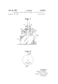
- FIG. 1 shows a diagrammatic arrangement of an internal combustion engine according to the invention
- FIG. 2 is an idealized crankshaft angle diagram
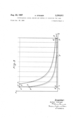
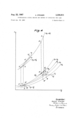
- FIGS. 3 and 4 are idealized P-V (pressure-volume) and T-S (temperature-entropy) diagrams respectively, useful in explaining the invention.
- reference character 2 designates an internal combustion engine having a reduced effective compression stroke, which engine may be of a type known per se.
- an exhaust gas turbine 4 driving a compressor 6 for supercharging of combustion air to be delivered to the engine through an air cooler 8.
- the exhaust gases from the engine pass through a conduit 10 and drive the gas turbine 4 which is mechanically coupled to the compressor 6.
- Air aspirated by the compressor is delivered at a line 12 which passes through the cooler 8 to the engine.
- a line 14 serves as a bypass for line 12 around the cooler 8.
- a coolant such as water is circulated through the cooler by means of a line 16.
- the cooler thus constitutes a heat exchanger through which there is circulated on the primary or hot side air compressed by the supercharger and through which there is circulated on the secondary or cool side a coolant fluid for removal of heat.
- Bypass line 14 includes a throttling element 20 which is adjusted in position by means of a controller 22, responsive to an engine parameter such as engine speed which varies according to the position of the engine in its range of operation. A signal representative of this parameter is delivered to controller 22 from the engine via a signal channel 24.
- the coolant line 16 may include an adjustable valve 26 or a bypass 28 having a valve 30 therein, or both, bypass 2% connecting the line 16 around the cooler and serving to shortcircuit the cooler.
- FIG. 2 shows in idealized form the crankshaft angle diagram of an engine having a reduced compression stroke.
- the engine may be assumed to have a single cylinder; alternatively the crank angle diagram of FIGURE 2 may be understood to refer separately to each of plural cylinders.
- the inlet valve for any one cylinder closes theoretically at bottom dead center (BDC), but in an engine having a shortened effective compression stroke, those valves close at an angle either before or after bottom dead center.
- FIG. 3 shows for comparison purposes idealized pressure volume diagrams of a standard four-stroke cycle engine in (solid lines) and of a four-stroke cycle engine having a shortened compression stroke (in dashed lines), both engines being assumed to be of the same capacity or power. Again, the discussion will be in terms of a single cylinder.
- relation (5) was chosen to insure equal mechanical peak stressing, whereas that of relation (6) corresponds to a condition found by experience to insure optimum combustion.
- the adiabatic exponent k is independent of the temperature and of gas composition.
- the solid lines denote the process for the standard four-stroke engine and the dashed lines denote the process for the four-stroke engine having .a reduced compression stroke.
- the designation of the points is very similar to that in FIG. 3 except that events in the turbo-supercharger and air cooler have also been included.
- the vertical lines 0-10 and 010' in FIG. 4 denote for the standard engine and for that having a shortened effective compression stroke respectively an adiabatic compression in the supercharger.
- the lines 10-2 correspond similarly to cooling of the charging air in the air cooler 8 to the temperature determined by the cooling water temperature flowing in line 16 of FIG. 1.
- the vertical line 2-3 represents the adiabatic compression in the engine
- the lines 34 and 4-5 denote the heat evolved in the cylinder by combusion of the fuel. Ideally, 22% of the heat is evolved at constant volume during the phase represented by passage from point 3 to point 4, whereafter the remaining 78% 5, 030 atmospheres absolute mi mi is supplied at constant pressure between points 4 and 5.
- shortened compression stroke process represented by dashed lines in FIG. 4 is that the removal of heat in the air cooler is greater than in the standard process. Consequently, the final temperature for a compression in the cylinder to a given final pressure is lower than in the standard process. And even though the same effective heat is supplied to the gas, the end temperature after combustion is lower in the shortened-stroke process than in the standard process, as indicated in FIG. 4 by the difference in temperature between points 5 and 5'. The other process temperatures are also lower in the shortenedstroke engine than in the standard engine, as the relative position of the points 3, 3', 4, 4 and 5, 5 in FIG. 4 shows.
- the T-S diagram also enables the following conclusion about exhaust loss to be made. Referred to the engine, the heat loss associated with the exhaust gases is calculated as follows:
- the diagram in FIG. 4 also shows that on partial load operation, since the charging pressure is less than for full load operation the compression temperature T';, which is also fairly low for full-load operation, may so drop that the engine ceases to operate on the diesel principle.
- the closure time of the inlet valve is moved nearer bottom dead center. That is, the closure time is moved towards its position in the standard process with the full compression stroke. This adjustment of the valve closure time must :be continuous in order to adapt to the state of engine operation, and therefore, considerably complicates the engine and increases the likelihood of disturbances.
- the final temperature in the cylinder near the end of the compression stroke is prevented from falling during partial load operation of the engine by a corresponding reduction in cooling of the charging air.
- One simple way of doing this is to use a bypass for the charging air, as shown at 14 in FIG. 1, such bypass extending around the cooler and having a throttle or closure element 20 adapted to be adjusted either manually, or automatically by a controller 22, in dependence upon an engine parameter which varies with the state of engine operation.
- the parameter can be, for instance, engine speed, engine torque, the quantity of fuel supplied per stroke, the fuel pump delivery pressure, the charging pressure of the air, the air temperature after compression in the supercharger, and so on.
- a similar bypass 28 can be provided in the coolant flow line 16 to the charging air cooler.
- the coolant flow through the cooler can be throttled 7 or stopped by a throttling element 26 as required. This kind of control is simple but has greater control lag as compared with bypassing the air.
- the controller 22 may operate either on the valve 20 in the bypass line 14 for combustion air, or on the valve 26 in the coolant flow line 16, or on the valve 30 in the coolant flow bypass line 28. However connected, the controller will be arranged to vary as a direct function of engine output the cooling of the combustion air delivered by the supercharger 6 to the engine.
- a supercharged four-stroke cycle diesel engine comprising a cylinder, an inlet valve for said cylinder set to close at a phase displaced from bottom dead center preceding the compression stroke, a supercharger, a combustion air cooler disposed between the supercharger and the cylinder, and means to vary the cooling efifect of said cooler as a direct function of engine power output.
Landscapes
- Engineering & Computer Science (AREA)
- Mechanical Engineering (AREA)
- General Engineering & Computer Science (AREA)
- Physics & Mathematics (AREA)
- Thermal Sciences (AREA)
- Chemical & Material Sciences (AREA)
- Combustion & Propulsion (AREA)
- Supercharger (AREA)
- Output Control And Ontrol Of Special Type Engine (AREA)
Applications Claiming Priority (1)
| Application Number | Priority Date | Filing Date | Title |
|---|---|---|---|
| CH124064A CH413494A (de) | 1964-01-31 | 1964-01-31 | Aufgeladene Dieselbrennkraftmaschine sowie Verfahren zu deren Betrieb |
Publications (1)
| Publication Number | Publication Date |
|---|---|
| US3336911A true US3336911A (en) | 1967-08-22 |
Family
ID=4205747
Family Applications (1)
| Application Number | Title | Priority Date | Filing Date |
|---|---|---|---|
| US428072A Expired - Lifetime US3336911A (en) | 1964-01-31 | 1965-01-26 | Supercharged diesel engine and method of operating the same |
Country Status (4)
| Country | Link |
|---|---|
| US (1) | US3336911A (de) |
| CH (1) | CH413494A (de) |
| GB (1) | GB1093430A (de) |
| NL (1) | NL6413534A (de) |
Cited By (13)
| Publication number | Priority date | Publication date | Assignee | Title |
|---|---|---|---|---|
| US4000725A (en) * | 1975-03-24 | 1977-01-04 | Cummins Engine Company, Inc. | Aftercooler coolant flow control for internal combustion engine |
| US4236492A (en) * | 1976-12-04 | 1980-12-02 | Klockner-Humboldt-Deutz Aktiengesellschaft | Internal combustion engine having a supercharger and means for cooling charged air |
| US4817386A (en) * | 1983-05-18 | 1989-04-04 | Oskar Schatz | Method for the supply of combustion air to the combustion chamber of an internal combustion engine |
| US5036668A (en) * | 1990-07-03 | 1991-08-06 | Allied-Signal Inc. | Engine intake temperature control system |
| EP1520965A1 (de) * | 2003-10-02 | 2005-04-06 | Ford Global Technologies, LLC, A subsidary of Ford Motor Company | Verfahren zur Entdrosselung einer Brennkraftmaschine und entdrosselte Brennkraftmaschine |
| US7178492B2 (en) | 2002-05-14 | 2007-02-20 | Caterpillar Inc | Air and fuel supply system for combustion engine |
| US7191743B2 (en) | 2002-05-14 | 2007-03-20 | Caterpillar Inc | Air and fuel supply system for a combustion engine |
| US7201121B2 (en) | 2002-02-04 | 2007-04-10 | Caterpillar Inc | Combustion engine including fluidically-driven engine valve actuator |
| US7204213B2 (en) | 2002-05-14 | 2007-04-17 | Caterpillar Inc | Air and fuel supply system for combustion engine |
| US7222614B2 (en) | 1996-07-17 | 2007-05-29 | Bryant Clyde C | Internal combustion engine and working cycle |
| US7252054B2 (en) | 2002-05-14 | 2007-08-07 | Caterpillar Inc | Combustion engine including cam phase-shifting |
| US7281527B1 (en) | 1996-07-17 | 2007-10-16 | Bryant Clyde C | Internal combustion engine and working cycle |
| US8215292B2 (en) | 1996-07-17 | 2012-07-10 | Bryant Clyde C | Internal combustion engine and working cycle |
Families Citing this family (4)
| Publication number | Priority date | Publication date | Assignee | Title |
|---|---|---|---|---|
| NL180868C (nl) * | 1974-11-20 | 1987-05-04 | Hubers Cornelius | Verbrandingsmotor met een buiten de cilinders liggende verbrandingskamer. |
| FR2397523A1 (fr) * | 1977-07-12 | 1979-02-09 | Alsacienne Constr Meca | Moteur diesel suralimente |
| SE460303B (sv) * | 1981-12-01 | 1989-09-25 | Volvo Ab | Anordning foer tillfoersel av foerbraenningsluft till cylindrarna i en foerbraenningsmotor |
| AT393539B (de) * | 1988-09-02 | 1991-11-11 | Steyr Daimler Puch Ag | Brennkraftmaschine mit einem aufladeaggregat fuer die ladeluft |
Citations (2)
| Publication number | Priority date | Publication date | Assignee | Title |
|---|---|---|---|---|
| US3029594A (en) * | 1960-11-10 | 1962-04-17 | Miller Ralph | Matched turbocharger and engine |
| GB950020A (en) * | 1961-12-18 | 1964-02-19 | Manfred Behr | Improvements relating to supercharged internal combustion engine cooling arrangements |
-
1964
- 1964-01-31 CH CH124064A patent/CH413494A/de unknown
- 1964-11-20 NL NL6413534A patent/NL6413534A/xx unknown
- 1964-12-31 GB GB53011/64A patent/GB1093430A/en not_active Expired
-
1965
- 1965-01-26 US US428072A patent/US3336911A/en not_active Expired - Lifetime
Patent Citations (2)
| Publication number | Priority date | Publication date | Assignee | Title |
|---|---|---|---|---|
| US3029594A (en) * | 1960-11-10 | 1962-04-17 | Miller Ralph | Matched turbocharger and engine |
| GB950020A (en) * | 1961-12-18 | 1964-02-19 | Manfred Behr | Improvements relating to supercharged internal combustion engine cooling arrangements |
Cited By (13)
| Publication number | Priority date | Publication date | Assignee | Title |
|---|---|---|---|---|
| US4000725A (en) * | 1975-03-24 | 1977-01-04 | Cummins Engine Company, Inc. | Aftercooler coolant flow control for internal combustion engine |
| US4236492A (en) * | 1976-12-04 | 1980-12-02 | Klockner-Humboldt-Deutz Aktiengesellschaft | Internal combustion engine having a supercharger and means for cooling charged air |
| US4817386A (en) * | 1983-05-18 | 1989-04-04 | Oskar Schatz | Method for the supply of combustion air to the combustion chamber of an internal combustion engine |
| US5036668A (en) * | 1990-07-03 | 1991-08-06 | Allied-Signal Inc. | Engine intake temperature control system |
| US7222614B2 (en) | 1996-07-17 | 2007-05-29 | Bryant Clyde C | Internal combustion engine and working cycle |
| US7281527B1 (en) | 1996-07-17 | 2007-10-16 | Bryant Clyde C | Internal combustion engine and working cycle |
| US8215292B2 (en) | 1996-07-17 | 2012-07-10 | Bryant Clyde C | Internal combustion engine and working cycle |
| US7201121B2 (en) | 2002-02-04 | 2007-04-10 | Caterpillar Inc | Combustion engine including fluidically-driven engine valve actuator |
| US7178492B2 (en) | 2002-05-14 | 2007-02-20 | Caterpillar Inc | Air and fuel supply system for combustion engine |
| US7191743B2 (en) | 2002-05-14 | 2007-03-20 | Caterpillar Inc | Air and fuel supply system for a combustion engine |
| US7204213B2 (en) | 2002-05-14 | 2007-04-17 | Caterpillar Inc | Air and fuel supply system for combustion engine |
| US7252054B2 (en) | 2002-05-14 | 2007-08-07 | Caterpillar Inc | Combustion engine including cam phase-shifting |
| EP1520965A1 (de) * | 2003-10-02 | 2005-04-06 | Ford Global Technologies, LLC, A subsidary of Ford Motor Company | Verfahren zur Entdrosselung einer Brennkraftmaschine und entdrosselte Brennkraftmaschine |
Also Published As
| Publication number | Publication date |
|---|---|
| NL6413534A (de) | 1965-08-02 |
| CH413494A (de) | 1966-05-15 |
| GB1093430A (en) | 1967-12-06 |
Similar Documents
| Publication | Publication Date | Title |
|---|---|---|
| US3257797A (en) | Tandem supercharging system | |
| US2670595A (en) | High-pressure supercharging system | |
| US4815423A (en) | Method for controlling the working cycle of an internal combustion engine | |
| US3355877A (en) | Supercharged diesel engine power plants | |
| US4333424A (en) | Internal combustion engine | |
| US4700542A (en) | Internal combustion engines and methods of operation | |
| US5255637A (en) | Internal combustion engine with adaptive control of compression ratio | |
| US2780912A (en) | Method and apparatus for varying the final compression temperature in a four cycle internal combustion engine | |
| JPS5870023A (ja) | 内燃機関の運転条件の改良方法および内燃機関 | |
| US9494075B2 (en) | Four-cycle internal combustion engine with pre-stage cooled compression | |
| US4230075A (en) | Internal combustion engine | |
| US3591958A (en) | Internal combustion engine cycle | |
| EP0095252A2 (de) | Brennkraftmaschine | |
| US3242665A (en) | Compound turbine engine | |
| US3180079A (en) | Apparatus for operating spark-ignition internal combustion engines | |
| US5199262A (en) | Compound four stroke internal combustion engine with crossover overcharging | |
| US2249997A (en) | Internal combustion method | |
| US5048473A (en) | Method and apparatus for equipping a two-stroke engine which is self-supercharged by post-charging and in which an admission duct provides pre-exhaust into a storage chamber | |
| EP0013180A1 (de) | Verbundbrennkraftmaschine | |
| US20070277793A1 (en) | Method for operating an internal combustion engine | |
| EP3225808B1 (de) | Verbundbrennkraftmaschine | |
| RU2044911C1 (ru) | Тепловой двигатель внутреннего сгорания | |
| Mitchell | Power Producing Characteristics of Diesel Engines | |
| Watson et al. | Introduction to turbocharging and turbochargers | |
| Birmann | Aerothermodynamic Considerations Involved in Turbocharging Four and Two-Cycle Diesel Engines |