US3337143A - Rock crusher - Google Patents
Rock crusher Download PDFInfo
- Publication number
- US3337143A US3337143A US322673A US32267363A US3337143A US 3337143 A US3337143 A US 3337143A US 322673 A US322673 A US 322673A US 32267363 A US32267363 A US 32267363A US 3337143 A US3337143 A US 3337143A
- Authority
- US
- United States
- Prior art keywords
- bonnet
- support
- bonnet support
- base frame
- crusher
- Prior art date
- Legal status (The legal status is an assumption and is not a legal conclusion. Google has not performed a legal analysis and makes no representation as to the accuracy of the status listed.)
- Expired - Lifetime
Links
- 239000011435 rock Substances 0.000 title description 27
- 230000008093 supporting effect Effects 0.000 claims description 22
- 230000009471 action Effects 0.000 claims description 6
- 230000000694 effects Effects 0.000 claims description 2
- 239000012530 fluid Substances 0.000 description 81
- 230000000712 assembly Effects 0.000 description 38
- 238000000429 assembly Methods 0.000 description 38
- 238000010276 construction Methods 0.000 description 6
- 230000008901 benefit Effects 0.000 description 5
- 230000008878 coupling Effects 0.000 description 5
- 238000010168 coupling process Methods 0.000 description 5
- 238000005859 coupling reaction Methods 0.000 description 5
- 239000000463 material Substances 0.000 description 3
- 230000000717 retained effect Effects 0.000 description 3
- 238000000545 stagnation point adsorption reflectometry Methods 0.000 description 3
- XEEYBQQBJWHFJM-UHFFFAOYSA-N Iron Chemical compound [Fe] XEEYBQQBJWHFJM-UHFFFAOYSA-N 0.000 description 2
- 230000008859 change Effects 0.000 description 2
- 238000010586 diagram Methods 0.000 description 2
- 230000009977 dual effect Effects 0.000 description 2
- 210000005069 ears Anatomy 0.000 description 2
- 125000006850 spacer group Chemical group 0.000 description 2
- 229910000617 Mangalloy Inorganic materials 0.000 description 1
- PWHULOQIROXLJO-UHFFFAOYSA-N Manganese Chemical compound [Mn] PWHULOQIROXLJO-UHFFFAOYSA-N 0.000 description 1
- 230000004913 activation Effects 0.000 description 1
- 238000004891 communication Methods 0.000 description 1
- 239000000428 dust Substances 0.000 description 1
- 230000008030 elimination Effects 0.000 description 1
- 238000003379 elimination reaction Methods 0.000 description 1
- 239000000945 filler Substances 0.000 description 1
- 229910052742 iron Inorganic materials 0.000 description 1
- 238000003754 machining Methods 0.000 description 1
- 229910052748 manganese Inorganic materials 0.000 description 1
- 239000011572 manganese Substances 0.000 description 1
- 230000007246 mechanism Effects 0.000 description 1
- 238000000034 method Methods 0.000 description 1
- 210000002445 nipple Anatomy 0.000 description 1
- PPKKOTLGXBHLAB-XVHSACDVSA-N nocii Chemical compound C([C@@H](C(=O)N[C@@H](CC(C)C)C(=O)N[C@H](C(=O)N[C@@H](CC(C)C)C(=O)N[C@@H](CO)C(=O)N[C@@H](CCSC)C(=O)N[C@@H](CCC(N)=O)C(=O)N[C@@H](CO)C(=O)N[C@@H](CO)C(=O)N[C@@H](CCC(N)=O)C(O)=O)C(C)C)NC(=O)[C@H](CCC(N)=O)NC(=O)[C@H](CCCNC(N)=N)NC(=O)[C@H](CCSC)NC(=O)[C@H](CC=1C=CC=CC=1)NC(=O)[C@H](CCC(O)=O)NC(=O)[C@H](CO)NC(=O)[C@@H](N)CC=1C=CC=CC=1)C1=CC=C(O)C=C1 PPKKOTLGXBHLAB-XVHSACDVSA-N 0.000 description 1
- 238000005728 strengthening Methods 0.000 description 1
- IEDVJHCEMCRBQM-UHFFFAOYSA-N trimethoprim Chemical compound COC1=C(OC)C(OC)=CC(CC=2C(=NC(N)=NC=2)N)=C1 IEDVJHCEMCRBQM-UHFFFAOYSA-N 0.000 description 1
Images


Classifications
-
- B—PERFORMING OPERATIONS; TRANSPORTING
- B02—CRUSHING, PULVERISING, OR DISINTEGRATING; PREPARATORY TREATMENT OF GRAIN FOR MILLING
- B02C—CRUSHING, PULVERISING, OR DISINTEGRATING IN GENERAL; MILLING GRAIN
- B02C2/00—Crushing or disintegrating by gyratory or cone crushers
- B02C2/02—Crushing or disintegrating by gyratory or cone crushers eccentrically moved
- B02C2/04—Crushing or disintegrating by gyratory or cone crushers eccentrically moved with vertical axis
- B02C2/045—Crushing or disintegrating by gyratory or cone crushers eccentrically moved with vertical axis and with bowl adjusting or controlling mechanisms
Definitions
- FIG. 4 is a horizontal section taken along line 44 nocii iiiis unn F 1;
- This invention relates to improvements in rock crushers and particularly to improvements in the mechanism for adjusting the positions of certain parts thereof.
- the mounting means for the bonnet support comprises a plurality of adjustment assemblies, each including a lower stack of shims disposed between the base frame and a flange on the bonnet support and determining the height of the bonnet unit, and an upper stack of shims above such flange serving as a storage place for unused shims.
- a draw bolt extends upwardly from the base frame and through the shim stacks and bonnet support flange and has a pair of nuts to enable a clamping pressure to be applied to the shim stacks and flange to clamp them against the base frame.
- the draw bolt also has a second function, that of forcing a segmented wedging ring upwardly between opposed portions of the base frame and the bonnet support, to fixedly hold the bonnet support against movement in a lateral direction relative to said base frame.
- a more specific object is to provide such a crusher in which expanders in the form of hydraulic motors are interposed in the assemblies to provide a hydraulic bonnet support clamp system, wherein the motors are hydraulically connected together for common pressure actuation and pressure release to facilitate much faster shim adjustment than possible with my prior crusher.
- a further object is to provide a crusher as just described which may be operated as a mechanical system in the event of failure of the hydraulic system, and also to provide a crusher in which pressure is maintained in such system by the accumulators of the main hydraulic system of the crusher.
- Another object is to provide a novel arrangement for breaking loose the wedging ring from its wedged position and also for raising the bonnet support.
- a still further object is to provide a novel arrangement of supporting the bowl from the bonnet.
- FIG. 1 is a vertical, midsectional, fragmentary view through a rock crusher of the present invention, FIG. 1 being taken along line 1-1 of FIG. 4;
- FIG. 2 is an enlarged view of a portion of the structure in FIG. 1;
- FIG. 3 is a horizontal, fragmentary section taken along line 3-3 of FIG. 1;
- FIG. 5 is a schematic diagram showing part of the hydraulic circuit of the bonnet support clamp system
- FIG. 6 is a fragmentary vertical section through a modified form of the invention.
- FIG. 7 is a fragmentary vertical section through another modified form of the invention.
- FIG. 8 is a schematic diagram showing the hydraulic circuit for the crusher shown in FIG. 6;
- FIG. 9 is a fragmentary vertical section through a further modified form of the invention.
- FIG. 10 is a fragmentary vertical section through the crusher of FIG. 9, but taken on another radial plane of the crusher.
- FIG. 11 is a fragmentary vertical section through still another modified form of crusher.
- FIGS. 1-5 of the present application has a main frame F which rotatably supports a camming member C which in turn rotatably supports a crusher head H.
- the camming member is driven by a drive system D to cause wobbling movement of the crusher head.
- a bonnet support 11 is supported on the frame F by a plurality of supporting assemblies A of the present invention, one being shown in FIG. 1 and twelve being shown in FIG. 4.
- the bonnet support supports a bonnet unit which includes a bonnet 13 and a bowl or concave 15.
- a hold-down system HDS for holding the bonnet 13 down against the bonnet support 11, and releasable when non-crushable matter enters the crusher to prevent damage to the crusher. Because certain parts of the hold-down system appear in the drawings in places where their identity would be helpful, a brief reference to such parts will now be made.
- the major part of the hold-down system is supported in spaced relation above the bonnet support by a plurality of spacer studs 21 (FIGS. 1 and 4), and the hold-down system includes a plurality of piston and cylinder units 22 which apply downward pressure on the bonnet unit through thrust pins 23 (FIGS. 1 and 4).
- the bonnet support is retained in fixed relation to the main frame F, both vertically and laterally, by the supporting'assemblies A. Since the assemblies are of identical construction, the detail construction of one will suifice.
- an assembly includes a vertical rod in the form of a draw bolt 31 which has a head 33 (FIG. 1) disposed beneath a curved segment 35 of a segmented wedging ring.
- a head 33 FIG. 1
- Two other segments 35a and 35b are shown in FIG. 3 in flanking relation to a fourth segment 350, which is shown in FIG. 1 on the opposite side of the frame F from segment 35.
- the wedging ring segments fit between a camming surface provided by an inwardly extending lip 37 on frame F and an opposed surface provided by an annular skirt 39 on the bonnet support 11.
- the shank of the draw bolt 31 projects upwardly through matching but somewhat oversize holes in the segment 35 and the inwardly extending lip 37.
- the draw bolt shank then extends upwardly through slots 41 (FIG. 1) of a lower stack S of shims, through an outwardly projecting annular flange 43 On the bonnet support 11, through an expander unit 45, and then through the slots 41 of an upper stack S of shims.
- a washer 47 fits on the upper end of the draw bolt, which end is threaded to receive a pair of jam nuts 49.
- the expander unit is best shown in FIG. 2 and includes an open top cylinder 61 having a depending tubular portion 62 fitting in a recess formed in the flange 43.
- a piston 63 slidably fits within the cylinder and slidably engages the draw bolt 31 and has a depending tubular portion 65 slidably fitting within a head 67 of the cylinder.
- Spaced seals at 69 and 71 are provided between the piston and cylinder. Since there is no seal between the draw bolt and either the piston or cylinder, the drawbolt need not have a specially machined surface.
- Fluid is supplied to the expander unit 45' through a nipple 73 which communicates with a manifold groove 75 in the periphery of the flange 43 of the bonnet support.
- a closure strip 76 closes the outer portion of the groove to provide a passageway.
- FIG. shows that the groove is connected by a conduit 77 to an accumulator 79 of the crusher.
- a valve 81 controls the flow of fluid from the accumulator to the groove.
- a valve 83 controls the discharge of fluid from the groove 75. The discharged fluid may be discarded or may be returned to the accumulator through a pump 84.
- valve 83 will be provided with a quick disconnect coupling 85 to enable it to be readily connected to a similar coupling 86 on a discharge or drain hose 87 to discharge the fluid into a fluid reservoir 88.
- the fluid can be returned to the pump 84 through a line 89.
- a pressure hose 90 from the pump 84 having a quick disconnect coupling 91, is connected to the coupling 85.
- the valve 83 is opened and pressure is built up in the manifold groove 75, after which the valve 81 is opened to inject fluid into the accumulator 79. Then valve 83 is closed to isolate the pump 84 from the overall hydraulic circuit of the crusher.
- the pump may be removed from the machine or may be permanently mounted on the machine, and may be manually operated or power operated.
- the accumulator 79 mentioned above is one of the accumulators already on the machine for supplying fluid under pressure to piston and cylinder units 22 of the hold-down system HDS.
- FIG. 1 ShOWs one of the stops 92 beneath the segment 35c. These stops merely limit downward movement of the segments after they have been released.
- a screw jack 93 (FIGS. 1 and 3) is provided for each wedging segment for breaking the segment away from its wedged position.
- the screw jacks are the same and so a description of the one shown in FIG. 1 will suflice.
- the jack 93 threads downwardly through a nut 95, which is threadedly mounted in the flange 43, and then extends downwardly toward and is in alignment with a headed break pin 97.
- the break pin 97 extends downwardly through an oversize hole in the frame lip 37 and bottoms in a blind hole 99 formed in the segment 350. In such position, the head 1111 of the pin 97 is slightly spaced from a seat 103 formed in the flange 43.
- a dirt shield 106 is provided on the piston 63 of each unit 45 and overlaps the associated cylinder 61.
- the bowl or concave is formed of manganese steel, which is barely machinable. I support this bowl from the bonnet 13 by means of a plurality of ears 109 (FIGS. 1 and 4), six being shown, which are cast on the bowl proper and project upwardly through openings or notches 113 formed in the bonnet.
- the openings 113 are defined by bosses 115 which have horizontal upper edges. Wedge pieces 117 are driven through the opening 119 in the ears 1119 and across such edges to draw the bowl upwardly against the bonnet. Thereafter a filler 121 can be poured into the space formed between the bowl and bonnet to form a goo-d load bearing material between the upper portion of the bowl and bonnet.
- I provide a dust guard shield 123 (FIG. 1) around the crusher to enclose the space between the flange 43 and the lip 37 to keep dirt from accumulating in the holes 0ccupie d by the break pins 97.
- the jack screws 93 are threaded downwardly into engagement with the break pins 97 which apply increasing pressure to the wedging ring segments until they break away from their wedge fit between the bonnet support 11 and the base frame F.
- the heads of the break pins then seat against the base frame so that continued downward movement of the jack screws 93 raises the bonnet support 11 until such movement is stopped by the pistons 63 jamming the upper stacks S and washers 47 against the nuts 49.
- the shims which were removed from the upper stacks S are placed on the lower stacks S
- the jack screws 93 are backed off to release the wedging ring segments.
- the valve 83 is closed and the valve 81 opened to apply pressure to the hydraulic circuit for the bonnet support. This expands the units 45 to force the draw bolts 31 upwardly to raise the wedging ring segments and force them back into wedging positions.
- a desired clamping pressure is applied to the shim stacks S and S
- the crusher is now ready for operation.
- the same procedure as above described is used, except that after the expander units are collapsed and the bonnet support is elevated sufiiciently to relieve the pressure on the lower stacks S the desired thickness shim or shims are removed from each lower stack. Then, after the bonnet support is lowered down onto the lower stacks S the shims which were removed from the lower stacks S are placed on the upper stacks S Next, the expander units are energized to wedge the wedging ring segments into place and clamp both sets of shims S and S in place.
- FIGS. 1-5 One of the primary advantages of the form of the invention disclosed in FIGS. 1-5 is that it is no longer necessary to loosen and tighten the nuts 49 in order to change the height of the bonnet support 11.
- loosening of the shim stacks can be quickly and simultaneously accomplished by merely releasing fiuid from expander units 45. Either before or after the bonnet support is raised, various shim adjustments may be efiected. It is still necessary to thread the jacks 93 up and down, but raising and lowering of the bonnet support must be performed in any event.
- there are only four jack screws for even a large machine it is evident that a machine such as in FIG.
- FIGS. 1-5 Another advantage of the form of the invention disclosed in FIGS. 1-5 is that should the hydraulic circuit for the bonnet support fail, such as for instance, because of the development of a leak in one of the expander units or because of rupture of a hydraulic line or passageway, the crusher could continue in operation until such time as it was convenient to shut it down by merely closing the valve 81, and adjusting the nuts 49 downwardly to cause the pistons 63 to bottom against the cylinders. This would provide a mechanical system generally equivalent to that of my prior application previously referred to.
- draw bolt 31 in FIG. 1 has a dual function of drawing up the wedging segments and also constituting a guide rod for the shims and expander units. It would be possible, of course, to separate these functions so that the guide rod was in the form of a stud threaded into the main frame, but the dual function arrangement shown has obvious advantages over such construction.
- the mechanical jack screw 93 of FIG. 1 has been replaced by a hydraulic jack which includes a hydraulic jack cylinder 131 mounted in a threaded hole in the flange 43' of the bonnet support 11.
- the jack also includes a piston 133 having a heavy rod 135 for engaging the break pin 97 of the frame F.
- I may provide for each of the wedge segments a pair of heavy coil springs 141 to apply a downward pressure on the wedge segment.
- One of such coil springs is shown in FIG. 7 applying a downward pressure on the wedge segment 350.
- the spring is retained in place by a threaded plug 142. In such a construction, when the draw bolts are released, the springs will urge the wedging segments to break loose.
- FIG. 8 illustrates a hydraulic circuit which includes a plurality of jacks of the type shown in FIG. 6.
- a pump 84 having an outlet hose 90' equipped with a quick disconnect coupling for connection to either a manifold jack line 138, as shown in full lines in FIG. 8, or to the groove 75 as shown in dotted lines.
- the reservoir 88 in FIG. 8 has a quick disconnect drain hose 87 which can be connected to either groove 75 or jack line 138.
- the pressure hose 90 is connected to the jack line 138 and the drain hose 87' is connected to the groove 75 for the expanders 45, as shown in solid lines in FIG. 8.
- the valve 81 at the accumulator 79 is closed and the manifold valve 83 is opened. Oil is pumped either by hand pump or power pump from pump 84' into the hydraulic jacks and surplus oil from expander 45 drains into the reservoir 88'. The proper shim adjustments are made and then the drain line 87' is connected to the jack line 138 to release pressure from the lifting jacks. Pressure line 90' is then connected to the manifold groove 75 to expand the expanders 45.
- the expansion of the expanders will pull the wedging segments upwardly so that the break pins 97 will collapse the jacks somewhat to eject some of the fluid in the jacks back into the reservoir 88.
- the valve 83 is closed and the accumulator valve 81 is opened. If the pump is separate from the crusher, it is then stored for future use or if the pump is a power pump mounted on the machine it will remain attached.
- FIGS. 9 and 10 show a further modified form of the invention in which the shims are eliminated.
- a large nut 201 which completely surrounds the crusher and has acme or buttress threads engaging similar threads on the frame F.
- the upper end of the nut rides in a groove 203 formed in the lower face of the flange 43" of the bonnet support 11".
- An'hydraulic jack system as shown in FIG. 9, like that shown in FIG. 6, is employed in this construction, although a mechanical jack system could also be employed.
- FIG. 10 shows that the draw bolts 31' have pistons 205' on the upper ends thereof riding within cylinders 207 which are threadedly mounted on the bonnet support from the cylinders 207 via a flange 43".
- the jacks When it is desired to elevate the bonnet support, the jacks are operated to release the bonnet support for upward movement, whereafter the nut 201 is turned by any suitable means, such as for instance a ratcheting arrangement, in a direction to cause it to raise to lift the bonnet support.
- the pistons 205 When the desired level has been obtained, the pistons 205 are actuated to draw the wedging segments upwardly to bind the bonnet support 11" in position. It is obvious from the above how the bonnet support will belowered.
- Fluid under pressure may be conducted to or released groove type passageway 209 formed in the flange 43", in the same manner as is shown in FIG. 5 for expander units 45.
- a suitable breather hole at 211 is provided for the upper end of each of the cylinders 207.
- a stop pin can be threaded through the main frame to a position below the head of the draw bolt to limit downward movement of the draw bolt.
- the draw rod 31" extends upwardly through a piston 63' and is threaded to receive jam nuts 49.
- a stack of emergency use shims S are shown above the nuts 49' and are retained in place by a nut 221.
- the piston 63' is much larger than the piston 63 and fits in a larger cylinder 61, which is mounted on the flange 43 of the frame F in much the same manner as cylinder 61 is mounted on flange 43 of frame F, and receives fluid in much the same manner.
- the piston 63 carries a dirt shield 106' which overlaps the cylinder 61'.
- FIG. 11 form of the invention is that the piston has s-uflicient travel to make shim adjustment unnecessary.
- the piston can be bottomed on the cylinder and the appropriate number and size of shims inserted beneath the nuts 49' to enable the draw rod 31" to continue to perform its retaining operation on the wedge segments (350 being shown) disposed between the bonnet support and the frame F and to continue its hold-down function in regard to flange 43 on the nut 201.
- the draw rod 31" has sufficient length so that the maximum setting (clearance) to be effected between the head H (not shown in FIG. 11) and bowl can be obtained without the use of shims. As the manganese bowl 15 wears, the clearance increases. However, the original maximum clearance can be again obtained by inserting an appropriate size shim or shims beneath the nuts 49'.
- bonnet 13 has been shown without the usual radial strengthening webs that it would normally have.
- a rock crusher comprising,
- bonnet support surrounding said head having flange portions overlying part of said base frame
- bonnet unit on said bonnet support cooperable with said head to define a crushing chamber, and means for supporting said bonnet support on and re- 'leasably securing said bonnet support to said frame including a plurality of support assemblies,
- each assembly including a vertical rod extending up- Wardly from said part of said base frame and movably projecting through an opening in said flange portions of said bonnet support,
- a piston and cylinder unit slidably surrounding said rod and disposed next to one stack of shims
- a rock crusher comprising,
- bonnet support surrounding said head having flange portions overlying part of said base frame
- bonnet unit on said bonnet support cooperable with said head to define a crushing chamber
- each assembly including a vertical rod extending upwardly from said part of said base frame and movably projecting through an opening in said flange portions of said bonnet support,
- a piston and cylinder unit slidably surrounding said rod and disposed next to one stack of shims
- wedging means disposed between upwardly converging surfaces of the base frame and said bonnet support
- a rock crusher comprising,
- bonnet support surrounding said head having flange portions overlying part of said base frame
- bonnet unit on said bonnet support cooperable with said head to define a crushing chamber
- each assembly including a vertical rod extending u-p- I wardly from said part of said base frame and movably projecting through an opening in said flange portions of said bonnet support,
- a piston and cylinder unit slidably surrounding said rod and disposed next to one stack of shims
- wedging means disposed between upwardly converging surfaces of the base frame and said bonnet support
- said rod extending downwardly and engaging said wedging means so as to cause a wedging action thereof upon activation of said unit.
- a rock crusher comprising,
- bonnet support surrounding said head having flange portions overlying part of said base frame
- bonnet unit on said bonnet support cooperable with said head to define a crushing chamber
- each assembly including a vertical rod extending upwardly from said part of said base frame and movably projecting through an opening in said flange portions of said bonnet support,
- a piston and cylinder unit slidably surrounding said rod and disposed next to one stack of shims
- the first named means exerting a downward force on said bonnet support which is greater than the holding force exerted by said hydraulic means.
- a rock crusher comprising,
- bonnet support surrounding said head having flange portions overlying art of said base frame
- bonnet unit on said bonnet support cooperable with said head to define a crushing chamber
- each assembly including a vertical rod extending upwardly from said part of said base frame and movably projecting through an opening in said flange portions of said bonnet support,
- a piston and cylinder unit slidably surrounding said rod and disposed next to one stack of shims,-
- said hydraulic means and said supply means having a common source of fluid under pressure.
- a rock crusher comprising,
- bonnet support surrounding said head having flange portions overlying part of said base frame
- bonnet unit on said bonnet support cooperable with said head to define a crushing chamber
- each assembly including a vertical rod extending upwardly from said part of said base frame and movably projecting through an opening in said flange portions of said bonnet support,
- a piston and cylinder unit slidably surrounding said rod and disposed next to one stack of shims
- said supply means being designed to supply fluid under pressure to said hydraulic motors when releasing fluid from said units of said support assemblies.
- a rock crusher comprising,
- bonnet support surrounding said head having flange portions overlying part of said base frame
- bonnet unit on said bonnet support cooperable with said head to define a crushing chamber
- each assembly including a vertical rod extending upwardly from said part of said base frame and movably projecting through an opening in said flange portions of said bonnet support,
- a piston and cylinder unit slidably surrounding said rod and disposed next to one stack of shims
- said hydraulic means including fluid accumulator means mounted on said crusher,
- valve means for closing off communication between said accumulator means and said assemblies when fluid pressure is released from said assemblies.
- a rock crusher comprising,
- bonnet support surrounding said head having flange portions overlying part of said base frame
- bonnet unit on said bonnet support cooperable with said head to define a crushing chamber
- each assembly including a vertical rod extending upwardly from said part of said base frame and movably projecting through an opening in said flange portions of said bonnet support,
- a piston and cylinder unit slidably surrounding said rod and disposed next to one stack of shims
- a rock crusher comprising, a base frame, a crusher head on said frame, a bonnet support surrounding said head having flange portions overlying part of said base frame, a bonnet unit on said bonnet support cooperable with said head to define a crushing chamber, and means for supporting said bonnet support on and releasably securing said bonnet support to said frame including a plurality of support assemblies, each assembly including a vertical rod extending upwardly from said part of said base frame and movably projecting through an opening in said flange portions of said bonnet support, a lower stack of slotted shims on said rod between said base frame and said flange portions, an upper stock of slotted shims on said rod between said flange portions and a stop on said rod, a piston and cylinder unit slidably surrounding said rod and disposed next to one stack of shims, and supply means for supplying fluid pressure to and releasing fluid pressure from said piston and cylinder unit, whereby when fluid pressure is released one or more shims can be
- a rock crusher comprising, a base frame, a crusher head on said frame, a bonnet support surrounding said head having flange portions overlying part of said base frame, a bonnet unit on said bonnet support cooperable with said head to define a crushing chamber, and means for supporting said bonnet support on and releasably securing said bonnet support to said frame including a plurality of support assemblies, each assembly including a vertical rod extending upwardly from said part of said base frame and movably projecting through an opening in said flange portions of said bonnet support, a lower stack of slotted shims on said rod between said base frame and said flange portions, an upper stack of slotted shims on said rod between said flange portions and a stop on said rod, a piston and cylinder unit slidably surrounding said rod and disposed next to one stack of shims, and supply means for supplying fluid pressure to and releasing fluid pressure from said piston and cylinder unit, whereby when fluid pressure is released one or more shims can be
- A'rock crusher comprising,
- bonnet support surrounding said head having flange portions overlying part of said base frame
- bonnet unit on said bonnet support cooperable with said head to define a crushing chamber
- each assembly including a vertical rod extending upwardly from said part of said base frame and movably projecting through an opening in said flange portions of said bonnet support,
- a piston and cylinder unit slid-ably surrounding said rod and disposed next to one stack of shims
- the last named means comprising jack screws threadedly mounted on said support and engaging break pins slidably received by said frame and engaging said wedging means.
- a rock crusher comprising,
- bonnet support surrounding said head having flange portions overlying part of said base frame
- bonnet unit on said bonnet support cooperable with said head to define a crushing chamber
- said support means including wedging means disposed between upwardly converging surfaces on said base frame and said bonnet support,
- said support means including hydraulic means operable when energized to eflfect wedging action of said wedgmg means,
- break pin means slidably mounted in said frame and engaging said wedging means
- a rock crusher comprising,
- bonnet support surrounding said head having flange portions overlying part of said base frame
- bonnet unit on said bonnet support cooperable with said head to define a crushing chamber
- a rock crusher comprising,-
- bonnet support surrounding said head having flange portions overlying part of said base frame
- bonnet unit on said bonnet support cooperable with said head to define a crushing chamber
- said support means including wedging means disposed between upwardly converging surfaces on said base frame and said bonnet support,
- said support means including hydraulic means operable when energized to effect wedging action of said wedging means
- break pin means slidablymounted in said frame and engaging said wedging means
- the last named means including a nut threadedly engaging said frame and slidably engaging said bonnet support in vertical thr-ust engagement therewith.
- a rock crusher comprising,
- bonnet support surrounding said head having flange portions overlying part of said base frame
- bonnet unit on said bonnet support cooperable with said head to define a crushing chamber
- each assembly including a vertical rod extending upwardly from said part of said base frame and movably projecting through an opening in said flange portions of said bonnet support,
- a piston and cylinder unit slidably surrounding said rod and disposed next to one stack of shims
- said shims being slotted so that they can be laterally removed and laterally inserted on said rod.
- a rock crusher comprising,
- bonnet support surrounding said head having flange portions overlying part of said base frame
- bonnet unit on said bonnet support cooperable with said head to define a crushing chamber
- each assembly including a vertical rod extending upwardly from said part of said base frame and movably projecting through an opening in said flange portions of said bonnet support,
- a piston and cylinder unit slidably surrounding said rod and disposed next to one stack of shims
- said stop on said rod being adjustable therealong so that in the event of failure of said unit, said stop can be adjusted along said rod to cause complete collapse of said unit so that it acts merely as a spacer, whereby said crusher can continue in operation until such time as it is convenient to cure such failure.
- a rock crusher comprising,
- bonnet support surrounding said head having flange portions overlying part of said base frame
- bonnet unit on said bonnet support cooperable With said head to define a crushing chamber
- each assembly including a vertical rod extending upwardly from said part of said base frame and movably projecting through an opening in said flange portions of said bonnet support,
- a piston and cylinder unit slidably surrounding said rod and disposed next to one stack of shims
- said piston having a dirt shield thereon disposed in overlapping relation with respect to said cylinder.
Landscapes
- Engineering & Computer Science (AREA)
- Mechanical Engineering (AREA)
- Food Science & Technology (AREA)
- Crushing And Grinding (AREA)
- Working Measures On Existing Buildindgs (AREA)
Description
2, 1967 W. JOHNSQN I 3,337,143
ROCK CRUSHER Filed Nov. 12 1963 4 Sheets-Sheet l LOU/.5 W JOHNSON llVl/E/VTUR BY BUC/(HORN, BLO/PE, KLAROU/ST 8 SPAR/(MAN ATTORNEYS Aug. 22, 1967 1.. w. JOHNSON 3,337,143
ROCK CRUSHER Filed Nov. 12, 1963 4 Sheets-Sheet 2 LOU/5' W JOHNSON Fig 5 By INVENTOR.
BUCK/ OHM BL ORE, KLAROU/ST 8 SPAR/(MAN ATTORNEYS INVE/VTUR ATTORNEYS Aug. 22, 1967 w. JOHNSON ROCK CRUSHER 4 Sheets-Sheet Filed Nov. 12 1963 l/ll Fig. .9
BUG/(HORN, BLORE, KLAROU/ST ,8 SPAR/(MAN U j 3,337,143 nited States Patent cc FIG. 4 is a horizontal section taken along line 44 nocii iiiis unn F 1;
Louis W. Johnson, 3440 Franklin Blvd., Eugene, Oreg. 97403 Filed Nov. 12, 1963, Ser. No. 322,673 19 Claims. (Cl. 241-215) This invention relates to improvements in rock crushers and particularly to improvements in the mechanism for adjusting the positions of certain parts thereof.
In my copending application entitled, Rock Crusher. Ser. No. 150,616, filed Nov. 2, 1961, now US. Patent No. 3,118,623, granted Jan. 21, 1964, I disclose a rock crusher which has a bonnet support mounted for vertical adjustment to vary the clearance between the bonnet unit and the crusher head to thereby change the size of the crushed rock leaving the crusher.
In such application, the mounting means for the bonnet support comprises a plurality of adjustment assemblies, each including a lower stack of shims disposed between the base frame and a flange on the bonnet support and determining the height of the bonnet unit, and an upper stack of shims above such flange serving as a storage place for unused shims. A draw bolt extends upwardly from the base frame and through the shim stacks and bonnet support flange and has a pair of nuts to enable a clamping pressure to be applied to the shim stacks and flange to clamp them against the base frame. The draw bolt also has a second function, that of forcing a segmented wedging ring upwardly between opposed portions of the base frame and the bonnet support, to fixedly hold the bonnet support against movement in a lateral direction relative to said base frame.
When adjusting the height of the bonnet support, the nuts must be loosened. Since a moderate size crusher will have around eight adjustment assemblies, and a large crusher around twelve assemblies, it is evident that it is time-consuming to first loosen the nuts of the assemblies to enable shim adjustment, and then tighten such nuts to maintain the adjustment.
It is a main object of the present invention to provide a rock crusher of the general type under consideration in which the shim adjustment can be accomplished much faster than'heretofore possible.
A more specific object is to provide such a crusher in which expanders in the form of hydraulic motors are interposed in the assemblies to provide a hydraulic bonnet support clamp system, wherein the motors are hydraulically connected together for common pressure actuation and pressure release to facilitate much faster shim adjustment than possible with my prior crusher.
A further object is to provide a crusher as just described which may be operated as a mechanical system in the event of failure of the hydraulic system, and also to provide a crusher in which pressure is maintained in such system by the accumulators of the main hydraulic system of the crusher.
Another object is to provide a novel arrangement for breaking loose the wedging ring from its wedged position and also for raising the bonnet support.
A still further object is to provide a novel arrangement of supporting the bowl from the bonnet.
Various other objects of the invention will be apparent from the following description taken in connection with the accompanying drawings wherein:
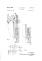
FIG. 1 is a vertical, midsectional, fragmentary view through a rock crusher of the present invention, FIG. 1 being taken along line 1-1 of FIG. 4;
FIG. 2 is an enlarged view of a portion of the structure in FIG. 1;
FIG. 3 is a horizontal, fragmentary section taken along line 3-3 of FIG. 1;
FIG. 5 is a schematic diagram showing part of the hydraulic circuit of the bonnet support clamp system;
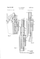
FIG. 6 is a fragmentary vertical section through a modified form of the invention;
FIG. 7 is a fragmentary vertical section through another modified form of the invention;
FIG. 8 is a schematic diagram showing the hydraulic circuit for the crusher shown in FIG. 6;
FIG. 9 is a fragmentary vertical section through a further modified form of the invention;
FIG. 10 is a fragmentary vertical section through the crusher of FIG. 9, but taken on another radial plane of the crusher; and
FIG. 11 is a fragmentary vertical section through still another modified form of crusher.
The general structure of the crusher, apart from the improvements of the present invention, is shown in my prior copending application previously referred to, and patricularly is similar to the second form of the invention there shown. Thus, the crusher in FIGS. 1-5 of the present application has a main frame F which rotatably supports a camming member C which in turn rotatably supports a crusher head H. The camming member is driven by a drive system D to cause wobbling movement of the crusher head.
A bonnet support 11 is supported on the frame F by a plurality of supporting assemblies A of the present invention, one being shown in FIG. 1 and twelve being shown in FIG. 4. The bonnet support supports a bonnet unit which includes a bonnet 13 and a bowl or concave 15.
Mounted on the bonnet support is a hold-down system HDS for holding the bonnet 13 down against the bonnet support 11, and releasable when non-crushable matter enters the crusher to prevent damage to the crusher. Because certain parts of the hold-down system appear in the drawings in places where their identity would be helpful, a brief reference to such parts will now be made. The major part of the hold-down system is supported in spaced relation above the bonnet support by a plurality of spacer studs 21 (FIGS. 1 and 4), and the hold-down system includes a plurality of piston and cylinder units 22 which apply downward pressure on the bonnet unit through thrust pins 23 (FIGS. 1 and 4).
The bonnet support is retained in fixed relation to the main frame F, both vertically and laterally, by the supporting'assemblies A. Since the assemblies are of identical construction, the detail construction of one will suifice.
Referring to FIGS. 1 and 2, an assembly includes a vertical rod in the form of a draw bolt 31 which has a head 33 (FIG. 1) disposed beneath a curved segment 35 of a segmented wedging ring. Two other segments 35a and 35b are shown in FIG. 3 in flanking relation to a fourth segment 350, which is shown in FIG. 1 on the opposite side of the frame F from segment 35.
The wedging ring segments fit between a camming surface provided by an inwardly extending lip 37 on frame F and an opposed surface provided by an annular skirt 39 on the bonnet support 11. The shank of the draw bolt 31 projects upwardly through matching but somewhat oversize holes in the segment 35 and the inwardly extending lip 37. The draw bolt shank then extends upwardly through slots 41 (FIG. 1) of a lower stack S of shims, through an outwardly projecting annular flange 43 On the bonnet support 11, through an expander unit 45, and then through the slots 41 of an upper stack S of shims. A washer 47 (FIG. 2) fits on the upper end of the draw bolt, which end is threaded to receive a pair of jam nuts 49.
The expander unit is best shown in FIG. 2 and includes an open top cylinder 61 having a depending tubular portion 62 fitting in a recess formed in the flange 43. A piston 63 slidably fits within the cylinder and slidably engages the draw bolt 31 and has a depending tubular portion 65 slidably fitting within a head 67 of the cylinder. Spaced seals at 69 and 71 are provided between the piston and cylinder. Since there is no seal between the draw bolt and either the piston or cylinder, the drawbolt need not have a specially machined surface.
Fluid is supplied to the expander unit 45' through a nipple 73 which communicates with a manifold groove 75 in the periphery of the flange 43 of the bonnet support. A closure strip 76 closes the outer portion of the groove to provide a passageway. FIG. shows that the groove is connected by a conduit 77 to an accumulator 79 of the crusher. A valve 81 controls the flow of fluid from the accumulator to the groove. A valve 83 controls the discharge of fluid from the groove 75. The discharged fluid may be discarded or may be returned to the accumulator through a pump 84. If the pump 84 is employed, it is contemplated that the valve 83 will be provided with a quick disconnect coupling 85 to enable it to be readily connected to a similar coupling 86 on a discharge or drain hose 87 to discharge the fluid into a fluid reservoir 88. The fluid can be returned to the pump 84 through a line 89. When it is desired to return fluid to the accumulator, a pressure hose 90 from the pump 84, having a quick disconnect coupling 91, is connected to the coupling 85. The valve 83 is opened and pressure is built up in the manifold groove 75, after which the valve 81 is opened to inject fluid into the accumulator 79. Then valve 83 is closed to isolate the pump 84 from the overall hydraulic circuit of the crusher. The pump may be removed from the machine or may be permanently mounted on the machine, and may be manually operated or power operated.
The accumulator 79 mentioned above is one of the accumulators already on the machine for supplying fluid under pressure to piston and cylinder units 22 of the hold-down system HDS.
There are a pair of stops in spaced relation beneath each of the wedging segments, and FIG. 1 ShOWs one of the stops 92 beneath the segment 35c. These stops merely limit downward movement of the segments after they have been released.
A screw jack 93 (FIGS. 1 and 3) is provided for each wedging segment for breaking the segment away from its wedged position. The screw jacks are the same and so a description of the one shown in FIG. 1 will suflice. The jack 93 threads downwardly through a nut 95, which is threadedly mounted in the flange 43, and then extends downwardly toward and is in alignment with a headed break pin 97. The break pin 97 extends downwardly through an oversize hole in the frame lip 37 and bottoms in a blind hole 99 formed in the segment 350. In such position, the head 1111 of the pin 97 is slightly spaced from a seat 103 formed in the flange 43.
When fluid is released from the expander units 45 of the supporting assemblies A of the bonnet support, the upward forces on the draw bolts 31 are released. Then, by threading down the jack screws, the pins 97 are forced downwardly to break the frictional grip between the wedging segments and the lip 43 and skirt 39. Thereafter the heads of the pins 97 seat in their seats so that further pressure applied against the break pins (when lifting the bonnet support) will be transmitted directly to the main frame F.
A dirt shield 106 is provided on the piston 63 of each unit 45 and overlaps the associated cylinder 61.
The bowl or concave is formed of manganese steel, which is barely machinable. I support this bowl from the bonnet 13 by means of a plurality of ears 109 (FIGS. 1 and 4), six being shown, which are cast on the bowl proper and project upwardly through openings or notches 113 formed in the bonnet. The openings 113 are defined by bosses 115 which have horizontal upper edges. Wedge pieces 117 are driven through the opening 119 in the ears 1119 and across such edges to draw the bowl upwardly against the bonnet. Thereafter a filler 121 can be poured into the space formed between the bowl and bonnet to form a goo-d load bearing material between the upper portion of the bowl and bonnet.
It is pointed out that the forces holding the bonnet support 11 down exceed the forces developed in the holddown system HDS particularly at the time when tramp iron or other non-crushable material enters the crusher. If this were not so, the bonnet support might be raised instead of the bonnet unit, which would allow the shims of the lower stacks S to become loose. In order that the forces holding the bonnet support down exceed the forces of the hold-down system, it is evident that the sum of the frictional forces created by the wedging segments and the hydraulic forces created by the expander units must substantially exceed that of the hold-down system. This can' be readily accomplished by merely making the effective areas of the pistons 63 of substantial size in relation to the pistons of the ho1d-down piston and cylinder units. In fact, I prefer to make the pistons of the units 45 the same size as the pistons of the units 22 for interchangeability of seals and ease of setting up machining operations, etc. Under these circumstances, despite the fact that the effective area of pistons 63 will be less than the effective area of a piston 22, because of the elimination of the area occupied by the draw bolt 31, the force exerted by the piston 63 when combined with the force exerted by the wedge segments will be greater than the forces exerted by the hydraulic units of the hold-down system. As a rule of thumb, I count on the wedging force as comprising about 50% of the force holding the bonnet support down and the expander units 45 supplying the remaining 50%.
If the wedging arrangement shown, for holding the bonnet support in a fixed position, is eliminated and some other means or merely .a sliding fit with the frame substituted therefor, the size of each of the pistons of the assemblies A would be increased in relation to the size of the piston and cylinder units for the hold-down system so that non-crushable material entering the crusher would lift the bonnet unit relative to the bonnet rather than lift the bonnet support relative to the frame.
I provide a dust guard shield 123 (FIG. 1) around the crusher to enclose the space between the flange 43 and the lip 37 to keep dirt from accumulating in the holes 0ccupie d by the break pins 97.
Operation Let it be assumed that it is desired to increase the maximum size of the crushed rock, which means that the bowl 15 must be raised to a higher position to provide a greater clearance between it and the head H. To accomplish this, the valve 81 (FIG. 5) at the accumulator 79 is closed and the valve 83 opened to release the pressure in the hydraulic circuit for the bonnet support, without releasing the pressure in the accumulator. Thus, the pistons of the expander units 45 bottom against the heads 67 of their cylinders to release the pressure on the upper and lower stacks of shims S and S respectively. Next, after removal of the shield 123, one or more shims are removed from each upper stack S (depending on the added clearance desired).
Now, the jack screws 93 are threaded downwardly into engagement with the break pins 97 which apply increasing pressure to the wedging ring segments until they break away from their wedge fit between the bonnet support 11 and the base frame F. The heads of the break pins then seat against the base frame so that continued downward movement of the jack screws 93 raises the bonnet support 11 until such movement is stopped by the pistons 63 jamming the upper stacks S and washers 47 against the nuts 49. Then the shims which were removed from the upper stacks S are placed on the lower stacks S Next, the jack screws 93 are backed off to release the wedging ring segments. Then, the valve 83 is closed and the valve 81 opened to apply pressure to the hydraulic circuit for the bonnet support. This expands the units 45 to force the draw bolts 31 upwardly to raise the wedging ring segments and force them back into wedging positions. In addition, a desired clamping pressure is applied to the shim stacks S and S The crusher is now ready for operation.
If it is desired to lower the position of the bonnet support 11, the same procedure as above described is used, except that after the expander units are collapsed and the bonnet support is elevated sufiiciently to relieve the pressure on the lower stacks S the desired thickness shim or shims are removed from each lower stack. Then, after the bonnet support is lowered down onto the lower stacks S the shims which were removed from the lower stacks S are placed on the upper stacks S Next, the expander units are energized to wedge the wedging ring segments into place and clamp both sets of shims S and S in place.
Since the expander units have only a short stroke (which is desirable in order to keep the height of the supporting mechanism for the bonnet support to a minimum) it is necessary to keep constant the height of the shim stacks of each draw bolt. This is done by replacing in one stack shims removed from the other. If this were not done, the nuts 49 would have to be adjusted, which is the timeconsuming operation that is eliminated by the present invention.
One of the primary advantages of the form of the invention disclosed in FIGS. 1-5 is that it is no longer necessary to loosen and tighten the nuts 49 in order to change the height of the bonnet support 11. With the hydraulic circuit, loosening of the shim stacks can be quickly and simultaneously accomplished by merely releasing fiuid from expander units 45. Either before or after the bonnet support is raised, various shim adjustments may be efiected. It is still necessary to thread the jacks 93 up and down, but raising and lowering of the bonnet support must be performed in any event. In addition, since there are only four jack screws for even a large machine, it is evident that a machine such as in FIG. 1 can be placed closer to a wall or other object than can a machine of my prior application because with my prior machine, room must be left in which to manipulate a wrench for loosening and tightening the many sets of nuts 49. Even closer positioning of the crusher can be accomplished if the mechanical jack screws 93 are replaced by hydraulic jacks such as shown in FIG. 6.
Another advantage of the form of the invention disclosed in FIGS. 1-5 is that should the hydraulic circuit for the bonnet support fail, such as for instance, because of the development of a leak in one of the expander units or because of rupture of a hydraulic line or passageway, the crusher could continue in operation until such time as it was convenient to shut it down by merely closing the valve 81, and adjusting the nuts 49 downwardly to cause the pistons 63 to bottom against the cylinders. This would provide a mechanical system generally equivalent to that of my prior application previously referred to.
It is pointed out that draw bolt 31 in FIG. 1 has a dual function of drawing up the wedging segments and also constituting a guide rod for the shims and expander units. It would be possible, of course, to separate these functions so that the guide rod was in the form of a stud threaded into the main frame, but the dual function arrangement shown has obvious advantages over such construction.
As shown in FIG. 6, the mechanical jack screw 93 of FIG. 1 has been replaced by a hydraulic jack which includes a hydraulic jack cylinder 131 mounted in a threaded hole in the flange 43' of the bonnet support 11. The jack also includes a piston 133 having a heavy rod 135 for engaging the break pin 97 of the frame F.
Referring to FIG. 7, I may provide for each of the wedge segments a pair of heavy coil springs 141 to apply a downward pressure on the wedge segment. One of such coil springs is shown in FIG. 7 applying a downward pressure on the wedge segment 350. The spring is retained in place by a threaded plug 142. In such a construction, when the draw bolts are released, the springs will urge the wedging segments to break loose.
It is possible to utilize in a crusher only the hydraulic jacks shown in FIG. 6, or only the coil springs shown in FIG. 7, but I prefer to use a combination of the two. If there are only coil springs, they would be of sutficient size to cause the wedging segments to break loose upon release of the draw bolts.
FIG. 8 illustrates a hydraulic circuit which includes a plurality of jacks of the type shown in FIG. 6. I have utilized in FIG. 8 a pump 84 having an outlet hose 90' equipped with a quick disconnect coupling for connection to either a manifold jack line 138, as shown in full lines in FIG. 8, or to the groove 75 as shown in dotted lines. The reservoir 88 in FIG. 8 has a quick disconnect drain hose 87 which can be connected to either groove 75 or jack line 138.
In operation, the pressure hose 90 is connected to the jack line 138 and the drain hose 87' is connected to the groove 75 for the expanders 45, as shown in solid lines in FIG. 8. The valve 81 at the accumulator 79 is closed and the manifold valve 83 is opened. Oil is pumped either by hand pump or power pump from pump 84' into the hydraulic jacks and surplus oil from expander 45 drains into the reservoir 88'. The proper shim adjustments are made and then the drain line 87' is connected to the jack line 138 to release pressure from the lifting jacks. Pressure line 90' is then connected to the manifold groove 75 to expand the expanders 45. The expansion of the expanders will pull the wedging segments upwardly so that the break pins 97 will collapse the jacks somewhat to eject some of the fluid in the jacks back into the reservoir 88. After the desired pressure has been created on the expanders 45, the valve 83 is closed and the accumulator valve 81 is opened. If the pump is separate from the crusher, it is then stored for future use or if the pump is a power pump mounted on the machine it will remain attached.
FIGS. 9 and 10 show a further modified form of the invention in which the shims are eliminated. In their place, there is provided a large nut 201 which completely surrounds the crusher and has acme or buttress threads engaging similar threads on the frame F. The upper end of the nut rides in a groove 203 formed in the lower face of the flange 43" of the bonnet support 11". An'hydraulic jack system as shown in FIG. 9, like that shown in FIG. 6, is employed in this construction, although a mechanical jack system could also be employed.
FIG. 10 shows that the draw bolts 31' have pistons 205' on the upper ends thereof riding within cylinders 207 which are threadedly mounted on the bonnet support from the cylinders 207 via a flange 43".
When it is desired to elevate the bonnet support, the jacks are operated to release the bonnet support for upward movement, whereafter the nut 201 is turned by any suitable means, such as for instance a ratcheting arrangement, in a direction to cause it to raise to lift the bonnet support. When the desired level has been obtained, the pistons 205 are actuated to draw the wedging segments upwardly to bind the bonnet support 11" in position. It is obvious from the above how the bonnet support will belowered.
Fluid under pressure may be conducted to or released groove type passageway 209 formed in the flange 43", in the same manner as is shown in FIG. 5 for expander units 45. A suitable breather hole at 211 is provided for the upper end of each of the cylinders 207.
It is particularly pointed out that it is only the nut 201 that is rotated and not the bonnet support and the structure thereabove. This arrangement has many advantages, one being that any shape hopper may be used on the superstructure of the crusher, such as for instance a rectangular hopper, without varying the orientation of such hopper with relation to the feeding chute or similar device which supplies rock to the crusher.
If desired, a stop pin can be threaded through the main frame to a position below the head of the draw bolt to limit downward movement of the draw bolt. This construction can be applied to any of the forms of the inventron.
In FIG. 11 the draw rod 31" extends upwardly through a piston 63' and is threaded to receive jam nuts 49. A stack of emergency use shims S are shown above the nuts 49' and are retained in place by a nut 221.
The piston 63' is much larger than the piston 63 and fits in a larger cylinder 61, which is mounted on the flange 43 of the frame F in much the same manner as cylinder 61 is mounted on flange 43 of frame F, and receives fluid in much the same manner. The piston 63 carries a dirt shield 106' which overlaps the cylinder 61'.
- The advantage of the FIG. 11 form of the invention is that the piston has s-uflicient travel to make shim adjustment unnecessary. In addition, in the event of failure of the circuit associated with the cylinder 61, the piston can be bottomed on the cylinder and the appropriate number and size of shims inserted beneath the nuts 49' to enable the draw rod 31" to continue to perform its retaining operation on the wedge segments (350 being shown) disposed between the bonnet support and the frame F and to continue its hold-down function in regard to flange 43 on the nut 201.
It is pointed out that the draw rod 31" has sufficient length so that the maximum setting (clearance) to be effected between the head H (not shown in FIG. 11) and bowl can be obtained without the use of shims. As the manganese bowl 15 wears, the clearance increases. However, the original maximum clearance can be again obtained by inserting an appropriate size shim or shims beneath the nuts 49'.
For convenience the bonnet 13 has been shown without the usual radial strengthening webs that it would normally have.
Having described the invention in what is considered to be the preferred embodiment thereof, it is desired that it be understood that the invention is not to be limited other than by the provisions of the following claims.
I claim:
1. A rock crusher comprising,
a base frame,
a crusher head on said frame,
a bonnet support surrounding said head having flange portions overlying part of said base frame,
a bonnet unit on said bonnet support cooperable with said head to define a crushing chamber, and means for supporting said bonnet support on and re- 'leasably securing said bonnet support to said frame including a plurality of support assemblies,
each assembly including a vertical rod extending up- Wardly from said part of said base frame and movably projecting through an opening in said flange portions of said bonnet support,
a lower stack of slotted shims on said rod between said base frame and said flange poi-tions,
an upper stack of slotted shims on said rod between said flange portions and a stop on said rod,
a piston and cylinder unit slidably surrounding said rod and disposed next to one stack of shims,
and supply means for supplying fluid pressure to and releasing fluid pressure from said piston and cylinder unit, whereby when fluid pressure is released one or more shirns can be removed from one stack and added to the other, and whereby when fluid pressure is supplied to such unit, said bonnet support is clamped down against said lower stack to determine the vertical position of said bonnet support.
2. A rock crusher comprising,
a base frame,
a crusher head on said frame,
a bonnet support surrounding said head having flange portions overlying part of said base frame,
a bonnet unit on said bonnet support cooperable with said head to define a crushing chamber, and
means for supporting said bonnet support on and releasably securing said bonnet support to said frame including a plurality of support assemblies,
each assembly including a vertical rod extending upwardly from said part of said base frame and movably projecting through an opening in said flange portions of said bonnet support,
a lower stack of slotted shims on said rod between said base frame and said flange portions,
an upper stack of slotted shims on said rod between said flange portions and a stop on said rod,
a piston and cylinder unit slidably surrounding said rod and disposed next to one stack of shims,
and supply means for supplying fluid pressure to and releasing fluid pressure from said piston and cylinder unit, whereby when fluid pressure is released one or more shims can be removed from one stack and added to the other, and whereby when fluid pressure is supplied to such unit, said bonnet support is clamped down against said lower stack to determine the vertical position of said bonnet support,
and means independent of said support assemblies for raising said bonnet support.
3. A rock crusher comprising,
a base frame,
a crusher head on said frame,
a bonnet support surrounding said head having flange portions overlying part of said base frame,
a bonnet unit on said bonnet support cooperable with said head to define a crushing chamber, and
means for supporting said bonnet support on and releasably securing said bonnet support to said frame including a plurality of support assemblies,
each assembly including a vertical rod extending upwardly from said part of said base frame and movably projecting through an opening in said flange portions of said bonnet support,
a lower stack of slotted shims on said rod between said base frame and said flange portions,
an upper stack of slotted shims on said rod between said flange portions and a stop on said rod,
a piston and cylinder unit slidably surrounding said rod and disposed next to one stack of shims,
and supply means for supplying fluid pressure to and releasing fluid pressure from said piston and cylinder unit, whereby when fluid pressure is released one or more shims can be removed from one stack and added to the other, and whereby when fluid pressure is supplied to such unit, said bonnet support is clamped down against said lower stack to determine the vertical position of said bonnet support,
wedging means disposed between upwardly converging surfaces of the base frame and said bonnet support,
and means whereby said piston and cylinder unit causes wedging action of said wedging means upon energization of said unit.
4. A rock crusher comprising,
a base frame,
a crusher head on said frame,
a bonnet support surrounding said head having flange portions overlying part of said base frame,
a bonnet unit on said bonnet support cooperable with said head to define a crushing chamber, and
means for supporting said bonnet support on and releasably securing said bonnet support to said frame including a plurality of support assemblies,
each assembly including a vertical rod extending upwardly from said part of said base frame and movably projecting through an opening in said flange portions of said bonnet support,
a lower stack of slotted shims on said rod between said base frame and said flange portions,
an upper stack of slotted shims on said rod between said flange portions and a stop on said rod,
a piston and cylinder unit slidably surrounding said rod and disposed next to one stack of shims,
and supply means for supplying fluid pressure to and releasing fluid pressure from said piston and cylinder unit, whereby when fluid pressure is released one or more shims can be removed from one stack and added to the other, and whereby when fluid pressure is supplied to such unit, said bonnet support is clamped down against said lower stack to determine the vertical position of said bonnet support,
and means independent of said support assemblies for raising said bonnet support,
wedging means disposed between upwardly converging surfaces of the base frame and said bonnet support,
' and means whereby said piston and cylinder unit causes wedging action of said wedging means upon energization of said unit.
5. A rock crusher comprising,
a base frame,
a crusher head on said frame,
a bonnet support surrounding said head having flange portions overlying part of said base frame,
a bonnet unit on said bonnet support cooperable with said head to define a crushing chamber, and
means for supporting said bonnet support on and releasably securing said bonnet support to said frame including a plurality of support assemblies,
each assembly including a vertical rod extending u-p- I wardly from said part of said base frame and movably projecting through an opening in said flange portions of said bonnet support,
a lower stack of slotted shims on said rod between said base frame and said flange portions,
an upper stack of slotted shims on said rod between said flange portions and a stop on said rod,
a piston and cylinder unit slidably surrounding said rod and disposed next to one stack of shims,
and supply means for supplying fluid pressure to and releasing fluid pressure from said piston and cylinder unit, whereby when fluid pressure is released one or more shims can be removed from one stack and added to the other, and whereby when fluid pressure is supplied to such unit, said bonnet support is clamped down against said lower stack to determine the vertical position of said bonnet support,
wedging means disposed between upwardly converging surfaces of the base frame and said bonnet support,
said rod extending downwardly and engaging said wedging means so as to cause a wedging action thereof upon activation of said unit.
6. A rock crusher comprising,
a base frame,
a crusher head on said frame,
a bonnet support surrounding said head having flange portions overlying part of said base frame,
a bonnet unit on said bonnet support cooperable with said head to define a crushing chamber, and
means for supporting said bonnet support on and releasably securing said bonnet support to said frame including a plurality of support assemblies,
each assembly including a vertical rod extending upwardly from said part of said base frame and movably projecting through an opening in said flange portions of said bonnet support,
a lower stack of slotted shims on said rod between said base frame and said flange portions,
an upper stack of slotted shims on said rod between said flange portions and a stop on said rod,
a piston and cylinder unit slidably surrounding said rod and disposed next to one stack of shims,
and supply means for supplying fluid pressure to and releasing fluid pressure from said piston and cylinder unit, whereby when fluid pressure is released one or more shims can be removed from one stack and added to the other, and wherebywhen fluid pressure is supplied to such unit, said bonnet support is clamped down against said lower stack to determine the vertical position of said bonnet support,
hydraulic means interconnecting said bonnet support and bonnet unit for holding said bonnet unit down against said bonnet support,
the first named means exerting a downward force on said bonnet support which is greater than the holding force exerted by said hydraulic means.
7. A rock crusher comprising,
a base frame,
a crusher head on said frame,
a bonnet support surrounding said head having flange portions overlying art of said base frame,
a bonnet unit on said bonnet support cooperable with said head to define a crushing chamber, and
means for supporting said bonnet support on and releasably securing said bonnet support to said frame including a plurality of support assemblies,
each assembly including a vertical rod extending upwardly from said part of said base frame and movably projecting through an opening in said flange portions of said bonnet support,
a lower stack of slotted shims on said rod between said base frame and said flange portions,
an upper stack of slotted shims on said rod between said flange portions and a stop on said rod,
a piston and cylinder unit slidably surrounding said rod and disposed next to one stack of shims,-
and supply means for supplying fluid pressure to and releasing fluid pressure from said piston and cylinder unit, whereby when fluid pressure is released one or more shims can be removed from one stack and added to the other, and whereby when fluid pressure is supplied to such unit, said bonnet support is clamped down against said lower stack to determine the vertical position of said bonnet support,
hydraulic means interconnecting said bonnet support and bonnet unit for holding said bonnet unit down against said bonnet support,
the first named means exerting a downward force on said bonnet support which is greater than the holding force exerted by said hydraulic means,
said hydraulic means and said supply means having a common source of fluid under pressure.
8. A rock crusher comprising,
a base frame,
a crusher head on said frame,
a bonnet support surrounding said head having flange portions overlying part of said base frame,
a bonnet unit on said bonnet support cooperable with said head to define a crushing chamber, and
means for supporting said bonnet support on and releasably securing said bonnet support to said frame including a plurality of support assemblies,
each assembly including a vertical rod extending upwardly from said part of said base frame and movably projecting through an opening in said flange portions of said bonnet support,
a lower stack of slotted shims on said rod between said base frame and said flange portions,
an upper stack of slotted shims on said rod between said flange portions and a stop on said rod,
a piston and cylinder unit slidably surrounding said rod and disposed next to one stack of shims,
and supply means for supplying fluid pressure to and releasing fluid pressure from said piston and cylinder unit, whereby when fluid pressure is released one or more shims can be removed from one stack and added to the other, and whereby when fluid pressure is supplied to such unit, said bonnet support is clamped down against said lower stack to determine the vertical position of said bonnet support,
and means independent of said support assemblies for raising said bonnet support,
the last named means including hydraulic motors,
said supply means being designed to supply fluid under pressure to said hydraulic motors when releasing fluid from said units of said support assemblies.
9. A rock crusher comprising,
a base frame,
a crusher head on said frame,
a bonnet support surrounding said head having flange portions overlying part of said base frame,
a bonnet unit on said bonnet support cooperable with said head to define a crushing chamber, and
means for supporting said bonnet support on and releasably securing said bonnet support to said frame including a plurality of support assemblies,
each assembly including a vertical rod extending upwardly from said part of said base frame and movably projecting through an opening in said flange portions of said bonnet support,
a lower stack of slotted shims on said rod between said base frame and said flange portions,
an upper stack of slotted shims on said rod between said flange portions and a stop on said rod,
a piston and cylinder unit slidably surrounding said rod and disposed next to one stack of shims,
hydraulic means interconnecting said bonnet support and bonnet unit for holding said bonnet unit down against said bonnet support,
The first named means exerting a downward force on said bonnet support which is greater than the holding force exerted by said hydraulic means,
said hydraulic means including fluid accumulator means mounted on said crusher,
means for connecting said accumulator means to said assemblies to supply fluid pressure thereto,
means for releasing fluid pressure from said assemblies,
and valve means for closing off communication between said accumulator means and said assemblies when fluid pressure is released from said assemblies.
10. A rock crusher comprising,
a base frame,
a crusher head on said frame,
a bonnet support surrounding said head having flange portions overlying part of said base frame,
a bonnet unit on said bonnet support cooperable with said head to define a crushing chamber, and
means for supporting said bonnet support on and releasably securing said bonnet support to said frame including a plurality of support assemblies,
each assembly including a vertical rod extending upwardly from said part of said base frame and movably projecting through an opening in said flange portions of said bonnet support,
a lower stack of slotted shims on said rod between said base frame and said flange portions,
an upper stack of slotted shims on said rod between said flange portions and a stop on said rod,
a piston and cylinder unit slidably surrounding said rod and disposed next to one stack of shims,
and supply means for supplying fluid pressure to and releasing fluid pressure from said piston and cylinder unit, whereby when fluid pressure is released one or more shims can be removed from one stack and added to the other, and whereby when fluid pressure is supplied to such unit, said bonnet support is clamped down against said lower stack to determine the vertical position of said bonnet support, said supply means including a passageway formed in said bonnet support, said cylinders of the assemblies being mounted on said bonnet support and communicating with said passageway. 11. A rock crusher comprising, a base frame, a crusher head on said frame, a bonnet support surrounding said head having flange portions overlying part of said base frame, a bonnet unit on said bonnet support cooperable with said head to define a crushing chamber, and means for supporting said bonnet support on and releasably securing said bonnet support to said frame including a plurality of support assemblies, each assembly including a vertical rod extending upwardly from said part of said base frame and movably projecting through an opening in said flange portions of said bonnet support, a lower stack of slotted shims on said rod between said base frame and said flange portions, an upper stock of slotted shims on said rod between said flange portions and a stop on said rod, a piston and cylinder unit slidably surrounding said rod and disposed next to one stack of shims, and supply means for supplying fluid pressure to and releasing fluid pressure from said piston and cylinder unit, whereby when fluid pressure is released one or more shims can be removed from one stack and added to the other, and whereby when fluid pressure is supplied to such unit, said bonnet support is clamped down against said lower stack to determine the vertical position of said bonnet support, said supply means including a passageway formed in said bonnet support, said cylinders of the assemblies being mounted on said bonnet support and communicating with said passageway, accumulator means mounted on said crusher and communicating with said passageway, and valve means for controlling the flow of fluid from said accumulator means to said passageway and controlling the discharge of fluid from said passageway. 12. A rock crusher comprising, a base frame, a crusher head on said frame, a bonnet support surrounding said head having flange portions overlying part of said base frame, a bonnet unit on said bonnet support cooperable with said head to define a crushing chamber, and means for supporting said bonnet support on and releasably securing said bonnet support to said frame including a plurality of support assemblies, each assembly including a vertical rod extending upwardly from said part of said base frame and movably projecting through an opening in said flange portions of said bonnet support, a lower stack of slotted shims on said rod between said base frame and said flange portions, an upper stack of slotted shims on said rod between said flange portions and a stop on said rod, a piston and cylinder unit slidably surrounding said rod and disposed next to one stack of shims, and supply means for supplying fluid pressure to and releasing fluid pressure from said piston and cylinder unit, whereby when fluid pressure is released one or more shims can be removed from one stack and added to the other, and whereby when fluid pressure is supplied to such unit, said bonnet support is clamped down against said lower stack to determine the vertical position of said bonnet support,
and means independent of said support assemblies for raising said bonnet support,
and .for breaking said wedging member away from its wedged position.
13. A'rock crusher comprising,
a base frame,
a crusher head on said frame,
a bonnet support surrounding said head having flange portions overlying part of said base frame,
a bonnet unit on said bonnet support cooperable with said head to define a crushing chamber, and
means for supporting said bonnet support on and releasably securing said bonnet support to said frame including a plurality of support assemblies,
each assembly including a vertical rod extending upwardly from said part of said base frame and movably projecting through an opening in said flange portions of said bonnet support,
a lower stack of slotted shims on said rod between said base frame and said flange portions,
an upper stack of slotted shims on said rod between said flange portions and a stop on said rod,
a piston and cylinder unit slid-ably surrounding said rod and disposed next to one stack of shims,
and supply means for supplying fluid pressure to and releasing fluid pressure from said piston and cylinder unit, whereby when fluid pressure is released one or more shims can be removed from one stack and added to the other, and whereby when fluid pressure is supplied to such unit, said bonnet support is clamped down against said lower stack to determine the vertical position of said bonnet support,
and means independent of said support assemblies for raising said bonnet support,
and for breaking said wedging member away from its wedged position,
the last named means comprising jack screws threadedly mounted on said support and engaging break pins slidably received by said frame and engaging said wedging means.
14. A rock crusher comprising,
a base frame,
a crusher head on said frame,
a bonnet support surrounding said head having flange portions overlying part of said base frame,
a bonnet unit on said bonnet support cooperable with said head to define a crushing chamber, and
support means for releasably securing said bonnet support to said base frame and providing for support of said bonnet support at various levels relative to said base frame,
said support means including wedging means disposed between upwardly converging surfaces on said base frame and said bonnet support,
said support means including hydraulic means operable when energized to eflfect wedging action of said wedgmg means,
break pin means slidably mounted in said frame and engaging said wedging means,
and jack means for engaging said break pin means for breaking said wedging means loose.
15. A rock crusher comprising,
a base frame,
a crusher head on said frame,
a bonnet support surrounding said head having flange portions overlying part of said base frame,
a bonnet unit on said bonnet support cooperable with said head to define a crushing chamber, and
support means for releasably securing said bonnet support to said base frame and providing for support of said bonnet support at various levels relative to said base frame,
16. A rock crusher comprising,-
a base frame,
a crusher head on said frame,
a bonnet support surrounding said head having flange portions overlying part of said base frame,
a bonnet unit on said bonnet support cooperable with said head to define a crushing chamber, and
support means for releasably securing said bonnet support to said base frame and providing for support of said bonnet support at various levels relative to said base frame,
said support means including wedging means disposed between upwardly converging surfaces on said base frame and said bonnet support,
said support means including hydraulic means operable when energized to effect wedging action of said wedging means,
break pin means slidablymounted in said frame and engaging said wedging means,
and jack means for engaging said break pin means for breaking said wedging means. loose,
and means in addition to said jack means for raising and lowering said bonnet support,
the last named means including a nut threadedly engaging said frame and slidably engaging said bonnet support in vertical thr-ust engagement therewith.
17. A rock crusher comprising,
a base frame,
a crusher head on said frame,
a bonnet support surrounding said head having flange portions overlying part of said base frame,
a bonnet unit on said bonnet support cooperable with said head to define a crushing chamber, and
means for supporting said bonnet support on and releasably securing said bonnet support to said frame including a plurality of support assemblies,
each assembly including a vertical rod extending upwardly from said part of said base frame and movably projecting through an opening in said flange portions of said bonnet support,
a lower stack of slotted shims on said rod between said base frame and said flange portions,
an upper stack of slotted shims on said rod between said flange portions and a stop on said rod,
a piston and cylinder unit slidably surrounding said rod and disposed next to one stack of shims,
and supply means for supplying fluid pressure to and releasing fluid pressure from said piston and cylinder unit, whereby when fluid pressure is-released one or more shims can be removed from one stack and added to the other, and whereby when fluid pressure is supplied to such unit, said bonnet support is clamped down against said lower stack to determine the vertical position of said bonnet support,
said shims being slotted so that they can be laterally removed and laterally inserted on said rod.
18. A rock crusher comprising,
a base frame,
a crusher head on said frame,
a bonnet support surrounding said head having flange portions overlying part of said base frame,
a bonnet unit on said bonnet support cooperable with said head to define a crushing chamber, and
means for supporting said bonnet support on and releasably securing said bonnet support to said frame including a plurality of support assemblies,
each assembly including a vertical rod extending upwardly from said part of said base frame and movably projecting through an opening in said flange portions of said bonnet support,
a lower stack of slotted shims on said rod between said base frame and said flange portions,
an upper stack of slotted shims on said rod between said flange portions and a stop on said rod,
a piston and cylinder unit slidably surrounding said rod and disposed next to one stack of shims,
and supply means for supplying fluid pressure to and releasing fluid pressure from said piston and cylinder unit, whereby when fluid pressure is released one or more shims can be removed from one stack and added to the other, and whereby when fluid pressure is supplied to such unit, said bonnet support is clamped down against said lower stack to determine the vertical position of said bonnet support,
said stop on said rod being adjustable therealong so that in the event of failure of said unit, said stop can be adjusted along said rod to cause complete collapse of said unit so that it acts merely as a spacer, whereby said crusher can continue in operation until such time as it is convenient to cure such failure.
19. A rock crusher comprising,
a base frame,
a crusher head on said frame,
a bonnet support surrounding said head having flange portions overlying part of said base frame,
a bonnet unit on said bonnet support cooperable With said head to define a crushing chamber, and
means for supporting said bonnet support on and releasably securing said bonnet support to said frame including a plurality of support assemblies,
each assembly including a vertical rod extending upwardly from said part of said base frame and movably projecting through an opening in said flange portions of said bonnet support,
a piston and cylinder unit slidably surrounding said rod and disposed next to one stack of shims,
and suply means for supplying fluid pressure to and releasing fluid pressure from said piston and cylinder unit,
said piston having a dirt shield thereon disposed in overlapping relation with respect to said cylinder.
References Cited UNITED STATES PATENTS 1,691,553 11/1928 Rumpel 241-215 2,090,449 8/1937 Knudtzen 241-299 2,579,516 12/1951 Roubal 241-215 2,594,080 4/1952 Shafter 241-299 2,679,984 6/1954 Gruender 241-215 2,908,448 10/1959 MacLeod 241-215 2,925,959 2/ 1960 Werner 241-207 3,019,994 2/1962 Symons 214-290 ROBERT c. RIORDON, Primary Examiner.
D. KELLY, Assistant Examiner.
Claims (1)
14. A ROCK CRUSHER COMPRISING, A BASE FRAME, A CRUSHER HEAD ON SAID FRAME, A BONNET SUPPORTING SURROUNDING SAID HEAD HAVING FLANGE PORTIONS OVERLYING PART OF SAID BASE FRAME, A BONNET UNIT ON SAID BONNET SUPPORT COOPERABLE WITH SAID HEAD TO DEFINE A CRUSHING CHAMBER, AND SUPPORT MEANS FOR RELEASABLY SECURING SAID BONNET SUPPORT TO SAID BASE FRAME AND PROVIDING FOR SUPPORT OF SAID BONNET SUPPORT AT VARIOUS LEVELS RELATIVE TO SAID BASE FRAME, SAID SUPPORT MEANS INCLUDING WEDGING MEANS DISPOSED BETWEEN UPWARDLY CONVERGING SURFACES ON SAID BASE FRAME AND SAID BONNET SUPPORT, SAID SUPPORT MEANS INCLUDING HYDRAULIC MEANS OPERABLE WHEN ENERGIZED TO EFFECT WEDGING ACTION OF SAID WEDGEING MEANS, BREAK PIN MEANS SLIDABLY MOUNTED IN SAID FRAME AND ENGAGING SAID WEDGING MEANS, AND JACK MEANS FOR ENGAGING SAID BREAK PIN MEANS FOR BREAKING SAID WEDGING MEANS LOOSE.
Priority Applications (2)
| Application Number | Priority Date | Filing Date | Title |
|---|---|---|---|
| US322673A US3337143A (en) | 1963-11-12 | 1963-11-12 | Rock crusher |
| US485460A US3281083A (en) | 1963-11-12 | 1965-09-07 | Rock crusher bowl support |
Applications Claiming Priority (1)
| Application Number | Priority Date | Filing Date | Title |
|---|---|---|---|
| US322673A US3337143A (en) | 1963-11-12 | 1963-11-12 | Rock crusher |
Publications (1)
| Publication Number | Publication Date |
|---|---|
| US3337143A true US3337143A (en) | 1967-08-22 |
Family
ID=23255920
Family Applications (1)
| Application Number | Title | Priority Date | Filing Date |
|---|---|---|---|
| US322673A Expired - Lifetime US3337143A (en) | 1963-11-12 | 1963-11-12 | Rock crusher |
Country Status (1)
| Country | Link |
|---|---|
| US (1) | US3337143A (en) |
Cited By (10)
| Publication number | Priority date | Publication date | Assignee | Title |
|---|---|---|---|---|
| US3396916A (en) * | 1966-10-28 | 1968-08-13 | Allis Chalmers Mfg Co | Fluid pressure operated adjustment and release for gyratory crushers and the like |
| US3604640A (en) * | 1968-03-08 | 1971-09-14 | Pegson Ltd | Hydraulic control for gyratory crusher |
| US3759453A (en) * | 1971-12-27 | 1973-09-18 | L Johnson | Rock crusher |
| US3887143A (en) * | 1974-05-28 | 1975-06-03 | Portec Inc | Gyratory crusher |
| US4477030A (en) * | 1980-09-18 | 1984-10-16 | Pettibone Corporation | Cone crushers |
| US4717084A (en) * | 1986-12-22 | 1988-01-05 | Cedarapids, Inc. | Hydraulic system for remote operable cone crushers |
| US20040035967A1 (en) * | 2002-08-23 | 2004-02-26 | Johnson Louis Wein | Gyratory crusher with hydrostatic bearings |
| US20090152385A1 (en) * | 2007-12-14 | 2009-06-18 | Cedarapids, Inc. | Screw adjust cone crusher |
| WO2015155062A1 (en) * | 2014-04-09 | 2015-10-15 | Thyssenkrupp Industrial Solutions Ag | Securing the shaft in a cone crusher |
| US20160051988A1 (en) * | 2014-08-19 | 2016-02-25 | Metso Minerals Industries, Inc. | Top service clamping cylinders for a gyratory crusher |
Citations (8)
| Publication number | Priority date | Publication date | Assignee | Title |
|---|---|---|---|---|
| US1691553A (en) * | 1926-12-20 | 1928-11-13 | Smith Engineering Works | Crusher |
| US2090449A (en) * | 1935-03-06 | 1937-08-17 | Sydvaranger As | Arrangement for securing of the bowl liner of cone crushers |
| US2579516A (en) * | 1950-08-28 | 1951-12-25 | Allis Chalmers Mfg Co | Gyratory crushfr with vertically adjustable head |
| US2594080A (en) * | 1947-06-09 | 1952-04-22 | Nordberg Manufacturing Co | Gyratory crusher |
| US2679984A (en) * | 1951-12-05 | 1954-06-01 | Nordberg Manufacturing Co | Pneumatic release for crushers |
| US2908448A (en) * | 1957-01-24 | 1959-10-13 | Lester R Macleod | Gyratory crusher |
| US2925959A (en) * | 1954-02-24 | 1960-02-23 | Nordberg Manufacturing Co | Pneumatic release recharging means |
| US3019994A (en) * | 1957-10-16 | 1962-02-06 | Nordberg Manufacturing Co | Hydraulic bowl release for cone crushers |
-
1963
- 1963-11-12 US US322673A patent/US3337143A/en not_active Expired - Lifetime
Patent Citations (8)
| Publication number | Priority date | Publication date | Assignee | Title |
|---|---|---|---|---|
| US1691553A (en) * | 1926-12-20 | 1928-11-13 | Smith Engineering Works | Crusher |
| US2090449A (en) * | 1935-03-06 | 1937-08-17 | Sydvaranger As | Arrangement for securing of the bowl liner of cone crushers |
| US2594080A (en) * | 1947-06-09 | 1952-04-22 | Nordberg Manufacturing Co | Gyratory crusher |
| US2579516A (en) * | 1950-08-28 | 1951-12-25 | Allis Chalmers Mfg Co | Gyratory crushfr with vertically adjustable head |
| US2679984A (en) * | 1951-12-05 | 1954-06-01 | Nordberg Manufacturing Co | Pneumatic release for crushers |
| US2925959A (en) * | 1954-02-24 | 1960-02-23 | Nordberg Manufacturing Co | Pneumatic release recharging means |
| US2908448A (en) * | 1957-01-24 | 1959-10-13 | Lester R Macleod | Gyratory crusher |
| US3019994A (en) * | 1957-10-16 | 1962-02-06 | Nordberg Manufacturing Co | Hydraulic bowl release for cone crushers |
Cited By (15)
| Publication number | Priority date | Publication date | Assignee | Title |
|---|---|---|---|---|
| US3396916A (en) * | 1966-10-28 | 1968-08-13 | Allis Chalmers Mfg Co | Fluid pressure operated adjustment and release for gyratory crushers and the like |
| US3604640A (en) * | 1968-03-08 | 1971-09-14 | Pegson Ltd | Hydraulic control for gyratory crusher |
| US3759453A (en) * | 1971-12-27 | 1973-09-18 | L Johnson | Rock crusher |
| US3887143A (en) * | 1974-05-28 | 1975-06-03 | Portec Inc | Gyratory crusher |
| US4477030A (en) * | 1980-09-18 | 1984-10-16 | Pettibone Corporation | Cone crushers |
| US4717084A (en) * | 1986-12-22 | 1988-01-05 | Cedarapids, Inc. | Hydraulic system for remote operable cone crushers |
| US20040035967A1 (en) * | 2002-08-23 | 2004-02-26 | Johnson Louis Wein | Gyratory crusher with hydrostatic bearings |
| US7048214B2 (en) * | 2002-08-23 | 2006-05-23 | Louis Wein Johnson | Gyratory crusher with hydrostatic bearings |
| US20090152385A1 (en) * | 2007-12-14 | 2009-06-18 | Cedarapids, Inc. | Screw adjust cone crusher |
| US7832669B2 (en) | 2007-12-14 | 2010-11-16 | Vendelin John C | Screw adjust cone crusher |
| WO2015155062A1 (en) * | 2014-04-09 | 2015-10-15 | Thyssenkrupp Industrial Solutions Ag | Securing the shaft in a cone crusher |
| CN106232234A (en) * | 2014-04-09 | 2016-12-14 | 蒂森克虏伯工业解决方案股份公司 | Fixing at gyratory crusher axis |
| CN106232234B (en) * | 2014-04-09 | 2019-11-08 | 蒂森克虏伯工业解决方案股份公司 | Shaft fixation in cone crushers |
| US10603668B2 (en) | 2014-04-09 | 2020-03-31 | Thyssenkrupp Industrial Solutions Ag | Securing the shaft in a cone crusher |
| US20160051988A1 (en) * | 2014-08-19 | 2016-02-25 | Metso Minerals Industries, Inc. | Top service clamping cylinders for a gyratory crusher |
Similar Documents
| Publication | Publication Date | Title |
|---|---|---|
| US3337143A (en) | Rock crusher | |
| US3887143A (en) | Gyratory crusher | |
| US3759453A (en) | Rock crusher | |
| US3009660A (en) | Release and adjustment for gyratory crushers | |
| US2791383A (en) | Hydraulic control for gyratory crusher | |
| US4615491A (en) | Gyratory crusher with automatic tramp iron release | |
| US4206699A (en) | Retracting bolster for a press | |
| US3140835A (en) | Bowl clamping mechanism for cone crushers | |
| US5261810A (en) | Closing and clamping system | |
| US3321182A (en) | Combination hydraulic jack and load holding mechanism | |
| CA3040065C (en) | Wedge ring auto unlock system and method | |
| US3140834A (en) | Seal for gyratory crushers | |
| US3473744A (en) | Jaw crusher adjustment | |
| US4059223A (en) | Centrifuge pressure relief device | |
| US4012000A (en) | Crushing machine clearing system | |
| US3281083A (en) | Rock crusher bowl support | |
| US3797759A (en) | Crusher adjusting system | |
| US3804342A (en) | Crusher release clearing system | |
| US3656199A (en) | Safety mechanism for a hydraulically operated dockboard | |
| US3038670A (en) | Hydraulic release for gyratory crushers and the like | |
| US3004524A (en) | Hydraulic cylinder and piston arrangement | |
| US3985309A (en) | Crusher clearing system | |
| US3397846A (en) | Hydraulic release for gyratory crushers | |
| US2199337A (en) | Percussive mechanism | |
| US5809875A (en) | Apparatus for crushing scrap vehicle wheels |
Legal Events
| Date | Code | Title | Description |
|---|---|---|---|
| AS | Assignment |
Owner name: IOWA MANUFACTURING COMPANY OF CEDAR RAPIDS, IOWA Free format text: MERGER;ASSIGNOR:EL-JAY, INC.;REEL/FRAME:003960/0831 Effective date: 19790226 |