US3337699A - Rotary electric tap switch with improved contact and detent means - Google Patents
Rotary electric tap switch with improved contact and detent means Download PDFInfo
- Publication number
- US3337699A US3337699A US556335A US55633566A US3337699A US 3337699 A US3337699 A US 3337699A US 556335 A US556335 A US 556335A US 55633566 A US55633566 A US 55633566A US 3337699 A US3337699 A US 3337699A
- Authority
- US
- United States
- Prior art keywords
- contact
- shaft
- spring
- index
- base
- Prior art date
- Legal status (The legal status is an assumption and is not a legal conclusion. Google has not performed a legal analysis and makes no representation as to the accuracy of the status listed.)
- Expired - Lifetime
Links
Images

Classifications
-
- H—ELECTRICITY
- H01—ELECTRIC ELEMENTS
- H01H—ELECTRIC SWITCHES; RELAYS; SELECTORS; EMERGENCY PROTECTIVE DEVICES
- H01H19/00—Switches operated by an operating part which is rotatable about a longitudinal axis thereof and which is acted upon directly by a solid body external to the switch, e.g. by a hand
- H01H19/02—Details
- H01H19/10—Movable parts; Contacts mounted thereon
- H01H19/11—Movable parts; Contacts mounted thereon with indexing means
-
- H—ELECTRICITY
- H01—ELECTRIC ELEMENTS
- H01H—ELECTRIC SWITCHES; RELAYS; SELECTORS; EMERGENCY PROTECTIVE DEVICES
- H01H19/00—Switches operated by an operating part which is rotatable about a longitudinal axis thereof and which is acted upon directly by a solid body external to the switch, e.g. by a hand
- H01H19/54—Switches operated by an operating part which is rotatable about a longitudinal axis thereof and which is acted upon directly by a solid body external to the switch, e.g. by a hand the operating part having at least five or an unspecified number of operative positions
- H01H19/56—Angularly-movable actuating part carrying contacts, e.g. drum switch
- H01H19/563—Angularly-movable actuating part carrying contacts, e.g. drum switch with an initial separation movement perpendicular to the switching movement
-
- H—ELECTRICITY
- H01—ELECTRIC ELEMENTS
- H01H—ELECTRIC SWITCHES; RELAYS; SELECTORS; EMERGENCY PROTECTIVE DEVICES
- H01H19/00—Switches operated by an operating part which is rotatable about a longitudinal axis thereof and which is acted upon directly by a solid body external to the switch, e.g. by a hand
- H01H19/54—Switches operated by an operating part which is rotatable about a longitudinal axis thereof and which is acted upon directly by a solid body external to the switch, e.g. by a hand the operating part having at least five or an unspecified number of operative positions
- H01H19/56—Angularly-movable actuating part carrying contacts, e.g. drum switch
- H01H19/58—Angularly-movable actuating part carrying contacts, e.g. drum switch having only axial contact pressure, e.g. disc switch, wafer switch
- H01H19/585—Angularly-movable actuating part carrying contacts, e.g. drum switch having only axial contact pressure, e.g. disc switch, wafer switch provided with printed circuit contacts
Definitions
- ABSTRACT OF THE DISCLOSURE A rotary electric tap switch having a sequential contact and detent indexing action effected through differential spring means, whereby spring load is maintained upon the detent means in its raising and lowering indexing action independently of the engagement of movable contacts with fixed contacts, and whereby the movable contacts are moved into and out of full contact relation with the fixed contacts with an optimum spring load applied in the normal full contact position and with gradually in creasing and decreasing spring loads applied to the movable contacts as they are moved respectively into and out of their normal full contact position, thus providing for a wiping non-arcing engagement and disengagement of the contacts in their transition between the normal full contact positions.
- the present invention relates to a rotary electric tap switch, particularly of the type having a central actuating shaft, a radial contact arm having contact elements at its ends for successive engagement with a series of spaced circumferentially arranged fixed contacts, and annular index cam means having a series of circumferentially arranged rise and fall formations numerically related to the fixed contact points for imparting engaging and disengaging movement to the contact elements carried by the contact arm.
- An object of the invention is to provide differential pressure applying means, whereby a maximum pressure is exerted in the normal engaged relation of the contact elements to maintain firm electrical contact, and gradually increased and reduced pressures are respectively exerted upon the contact elements during transition into and out of their normal engaged relation.
- the contact elements have a gradual lowering and wiping contact action as they are engaged with the fixed contacts, and a gradual lifting-off and wiping contact action as they are disengaged from the fixed contacts.
- FIG. 1 is a side elevation of a rotary tap switch according to one embodiment of the invention, and shown in the normal contact or current conducting position;
- FIG. 2 is a plan view
- FIG. 3 is a vertical sectional view taken along the line 33 of FIG. 2;
- FIG. 4 is a side elevation of the index drive bar member
- FIG. 5 is a top plan view thereof
- FIG. 6 is a top plan view of the contact blade
- FIG. 7 is a side elevation thereof
- FIG. 8 is a perspective view of the pressure transmitting sleeve
- FIG. 9 is a side elevation of the bearing and index cam member
- FIG. 10 is a top plan view thereof
- FIG. 11 is a side elevation showing the contact blade in a lift-oft position
- FIG. 12 is a top plan view thereof
- FIG. 13 is a side elevation showing the contact blade in a fully disengaged position
- FIG. 14 is a top plan view thereof
- FIG. 15 is a side elevation of a modified form of the invention.
- FIG. 16 is a top plan view thereof
- FIG. 17 is a vertical sectional view taken along the line 17-17 of FIG. 16;
- FIG. 18 is a top plan view of the ball carrier employed in the modification of FIG. 15;
- FIG. 19 is a side elevation thereof
- FIG. 20 is a top plan view of the index drive bar member
- FIG. 21 is a side elevation thereof
- FIG. 22 is a top plan view of the contact blade
- FIG. 23 is a side elevation thereof
- FIG. 24 is a side elevation of the bearing and index cam member
- FIG. 25 is a top plan view thereof.
- the rotary electric tap switch according to the exemplary embodiment of the invention illustrated therein comprises a printed circuit board 10, formed of phenolic or other suitable dielectric material and provided substantially centrally with a circular opening 11.
- a printed circuit board 10 formed of phenolic or other suitable dielectric material and provided substantially centrally with a circular opening 11.
- a first circumferential series of contact pads 12 joined together by a circular ring 13, and connected by a cur rent conducting lead 14 extending outwardly from one of the pads 12 with a connector 15 secured upon one edge of the board.
- a second circumferential series of contact pads 16 in radial alignment with the pads 12 and individually connected by current conducting leads 17 to connectors 18 secured upon opposite edges of the board, half of the pads preferably being connected to connectors provided along one edge of the board and the other half being connected to connect ors provided along the opposite edge.
- the pads and current conducting leads are of copper foil deposited upon the board 10 by methods well known in the art of printed circuit boards and the connectors are preferably clipped upon the board edges in current conducting contact with the leads.
- a bearing and index cam member 19, shown in detached relation in FIGS. 9 and 10, is mounted upon the peak of each index corrugations is in radial line with the the board the radial center line of a respective contact pad 16.
- the sleeve 20 is of smaller diameter than the opening 11 and the index flange is of greater diameter, and in the assembled relation upon the board, the index flange is disposed at the upper side of the board with its outer periphcry in outwardly spaced concentric relation to the opening wall, while the sleeve 20 is disposed in concentric relation within the opening 11 in inwardly spaced relation to the opening wall.
- the bearing and index member 19 is secured to the board by integral outwardly offset lugs 23 projecting downwardly from the edge of the flange 21, which are engaged downwardly through slots 24 provided in the board in the dot-and-dash line position shown in FIG. 9 and are thereupon bent outwardly against the underside of the board as clearly seen in FIG. 3.
- An actuating shaft 25 is fitted within the sleeve 20 for rotary and sliding movement therein, one end of the shaft extending below the sleeve and having engaged thereon a thumb-knob .26 formed of suitable dielectric material and secured to the shaft by a set screw 27, while the other end of the shaft extends above the index flange and is provided with flat faces 28-28 at its opposite sides for the purpose of keying certain parts of the switch thereto, as will presently more fully appear.
- the shaft In normally spaced relation below the lower end of the sleeve 20 the shaft is provided with an abutment washer 29 disposed against a split spring ring 30 having snap engagement in an annular groove 31 of the shaft, and between the washer 29 and the underside of the index flange 21 there is disposed about the sleeve 20 a helical expansion spring 32 normally exerting downward pressure upon the shaft.
- An index drive bar member 33 illustrated in detached relation in FIGS. 4 and 5, is keyed upon the shaft 25 and for this purpose is provided with a central circular disc portion 34 having a shaft engaging opening 35 corresponding in shape to the cross-sectional shape of the upper flat-sided end portion of the shaft.
- a central circular disc portion 34 having a shaft engaging opening 35 corresponding in shape to the cross-sectional shape of the upper flat-sided end portion of the shaft.
- an annular series of radially disposed index corrugations 36 which in the normal position have fitting complementary engagement at their underside with the upper side of the index cam corrugations 22.
- a sleeve 37 shown in detached relation in FIG. 8, having a bore corresponding to the cross-sectional shape of the upper flat-sided end portion of the shaft, is engaged in keyed relation upon the shaft, with its lower end hearing upon the upper side of the disc portion 34 of the index drive bar member, and with its upper end engaged with an abutment washer 38 engaged upon the upper end portion of the shaft and retained thereon by a split spring ring 39 having snap engagement in an annular groove 40 in the shaft.
- the assembly is such that the spring 32 in exerting downward pressure upon the shaft 25 also exerts downward pressure upon the index drive bar member through the washer 38 and the sleeve 37, to thus press the index corrugations 36 into engagement with the index cam corrugations 22.
- the spacing of the lower end of the sleeve 20 from the abutment ring 29 permits limited upward sliding movement of the shaft in the sleeve 20, so that upon turning the shaft through the thumb-knob 26 the index drive bar is intermittently raised and lowered as the index corrugations 36 ride in step-by-step sequence over the index cam corrugations 22.
- a contact blade member 41 Associated with the index drive bar is a contact blade member 41, shown in detached relation in FIGS. 6 and 7, which comprises an intermediate disc portion 42 provided with a noncircular opening 43, corresponding in shape to the external shape of the sleeve 37 with which it is slidably engaged.
- An arm 44 extends radially outwardly from the disc portion 42 at one side and is provided at its outer end with a contact button 45 normally engaged with one of the contact pads 16, while at the opposite side there is provided a relatively shorter arm 46 provided at its outer end with a contact button 47, which normally engages one of the contact pads 12 in diametric line with the contact pad 16 engaged by the button 45.
- the arm 44 is provided with a downwardly inclined intermediate portion 48, preferably provided with an embossed stiffening rib 49 and the arm 46 is provided with an intermediate offset bend 46% The outer ends of the arms are thus downwardly offset from the intermediate disc portion 42,
- the arm 44 is positioned within a channel shaped extension 50 at one side of the index drive bar having a pair of lugs 51 extended inwardly over the arm 44, and similarly the arm 46 is positioned within a channel extension 52 at the opposite side having a pair of lugs 53 extending over the arm 46.
- the upward spacing of the lugs 51 and 53 from the base walls of the extensions 50 and 52 is such as to permit of limited relative vertical movement between the index drive bar and the contact blade member during the indexing operation, as will presently more fully appear.
- a helical expansion spring 54 Interposed between the upper side of the inter-mediate disc portion 42 of the contact blade member and the abutment washer 38 is a helical expansion spring 54, the expansive pressure of which is substantially less than that of the spring 32.
- the relationship of the two springs to the contact blade is such that during each indexing cycle there is a differential spring pressure applied to the contact blade whereby in the normal contact position the relatively greater pressure of the spring 32 is exerted to maintain the contact buttons in firm relation with the contact pads, while in the transitory movement during indexing from one station to the next the relatively strong pressure of the spring 32 is diverted while the relatively lighter pressure of the spring 54 takes over, so that as the contact buttons are moved out of full contacting position, they are in wiping contact with the pads under gradually decreasing pressure, thus providing a lingering, self-cleaning rubbing contact free from arcing. Conversely, as the contact buttons move into full contacting position, they engage the pads under gradually increasing pressure.
- FIGS. 11-14 The operation of the switch during indexing is illustrated in FIGS. 11-14 in comparison with the normal full contact position of the switch illustrated in FIGS. 1-3.
- the index drive bar member 33 is in full nesting engagement with the index cam member 22 under the pressure of the spring 32, which normally exerts a downward force upon the shaft 25 and through the washer 38 and sleeve 37 transmits such downward force upon the index drive bar member.
- the lugs 51 and 53 are in engagement with the upper side of the contact blade 41 and, by virtue of the fact that the downward pressure of the spring 54 upon the contact blade is substantially lighter than that of spring 32, the pressure of the stronger spring 32 is exerted through the lugs 51 and 53 directly upon the contact blade to maintain the contact buttons 45 and 47 in firm contact relation with the respective contact pads 16 and 12.
- the corrugations of the index drive bar 33 first ride up upon the inclined faces of the corrugations of the index cam 22 as seen in FIG. 11, causing the lugs 51 and 53 to move upwardly out of engagement with the contact blade member 41, so that the relatively stronger pressure of the spring 32 is diverted from the contact blade and at the same time the relatively lighter pressure of the spring 54 is exerted thereon.
- the contact buttons move from the full contact position as seen in FIGS. 1-3, they remain in contact with the contact pads but with substantially reduced spring pressure, so that the disengagement is through a smooth wiping contact action under gradually decreasing pressure to the point where the index drive bar member reaches its fully raised position as seen in FIG. 13, where the contact buttons are at the intermediate point between adjacent contact pads, and where the contact blade member is pressed against the bottom walls of the channel portions 50 and 52 of the index drive bar member under the pressure of the spring 54.
- the contact buttons are gradually lowered and engage the contact pads with a smooth wiping action under pressure of the spring 54, with the pressure gradually increasing as the index drive bar member is lowered into full nesting engagement with the cam index member 22, at which point the lugs 51 and 53 engage the contact blade under the relatively greater pressure of the spring 32.
- FIGS. 15-25 there is illustrated a modified form of the invention comprising a circular base 55 formed of suitable dielectric insulating material and provided near its outer periphery with a circumferential series of raised contacts 56, each preferably secured by swedging a stud projecting '57 within a hole 58 in the base, with an apertured terminal connector 59 interposed beneath the contact, and projecting beyond the periphery of the base.
- An even number of contacts 56 are provided in equally spaced relation, so that diametrically opposite contacts are adapted to be connected in the same circuit, such circuit being closed by a current conducting contact blade connected between the diametrically opposite contacts, as will presently more fully appear. While four such contacts are illustrated, it will be understood that any desired even number of contacts may be provided.
- a circular opening 60 is provided centrally of the base 55 in which there is engaged a cam bushing member 61 comprising a cylindrical tubular bearing bushing 62 projecting downwardly from the base, and provided at its upper end with a flange 63 engaged with the upper side of the base and secured thereto by downwardly projecting lugs 64 at its periphery engaged in slots 65 in the base and bent over inwardly against the underside of the base.
- a cam bushing member 61 comprising a cylindrical tubular bearing bushing 62 projecting downwardly from the base, and provided at its upper end with a flange 63 engaged with the upper side of the base and secured thereto by downwardly projecting lugs 64 at its periphery engaged in slots 65 in the base and bent over inwardly against the underside of the base.
- the flange constitutes an indexing cam and for this purpose is provided with a plurality of circular socket holes 66, corresponding in number to and radially aligned with the contacts 56, each said hole being provided at opposite sides with radially disposed cam projections 67 and 68, preferably in the form of embossed ribs convexly curved in cross section so as to provide inclined entrance and exit cam surfaces in relation to the holes.
- An actuating shaft 69 is rotatably fitted within the bushing 62, one end of the shaft extending below the bushing and having engaged thereon a thumb knob 70 formed of suitable dielectric material and secured by a set screw 71, while the other end extends above the flange 63 and is provided with flat faces 72-72 at its opposite sides, for the purpose of keying certain parts of the switch thereto, as will presently more fully appear.
- a split spring ring 73 having snap engagement in an annular groove 74 in the shaft is engaged with the lower end of the bushing.
- an abutment washer 75 having an aperture 76 corresponding in shape to the cross-sectional shape of the upper fiatted portion of the shaft, whereby the washer is non-rotatably engaged with the shaft, being retained in place by a split spring ring 77 engaged in an annular groove 78 in the shaft.
- a ball drive bar 79 shown in detail in FIGS. 18 and 19, is provided centrally with an aperture 80 corresponding in shape to the cross-sectional shape of the flatted portion of the shaft, whereby the bar has keyed axially sliding engagement with the shaft.
- the bar In diametrically aligned relation at each side of the aperture 80 the bar is provided with a pair of upwardly extending cylindrical flanges 81-81 providing tubular retainers for a pair of index balls 82-82, which normally seat in the pair of diametrically opposite socket holes 66-66 of the cam flange 63, and which through turning of the shaft as the switch is moved from one station tothe next are adapted to be raised from the socket holes through riding up the cam ribs 67 and to be lowered into the socket holes through riding down the cam ribs 68.
- a contact blade drive bar 84 shown in detail in FIGS. 20 and 21, is provided centrally with an aperture 85 corresponding in shape to the cross-sectional shape of the flatted end of the shaft 69 and has keyed sliding engagement therewith.
- the drive bar is supported upon the pair of index balls 82-82 and is provided along its longitudinal edges with positioning flanges 86-86, between which are engaged the tubular flanges 81-81 of the ball drive bar 79. The ball drive bar and the contact blade drive bar thus keyed together for rotation with the shaft 69.
- a helical spring 87 is disposed in surrounding relation to the upper end portion of the shaft 69 beneath the abutment washer 75 and exerts downward pressure uponthe contact blade drive bar 84, which in turn exerts downward pressure upon the balls 83 to normally seat them in the socket holes 66.
- the balls 82 rise out of seating engagement in the holes 66, causing the contact drive bar to be raised against the pressure of the spring 87.
- a contact blade member 88 shown in detail in FIGS. 22 and 23, is keyed to the contact drive bar 84, as will presently more fully appear, and comprises an intermediate ring shaped portion 89 having an upwardly extending circular rim 90 at its inner edge, and a pair of radially extending arms 9191 having cont-act buttons 9292 secured upon their outer ends for contact wtih a pair of diametrically opposite contacts 57 of the base 56.
- Each contact button is secured by a riveted stud 93 engaged in a hole 94 in the base and its lower contact face 95 is preferably convexly curved.
- each end of the contact blade drive bar 84 there is provided a pair of angular lugs 9696 engaged with the side edges of the arms 91 of the contact blade and extended inwardly over the upper surface thereof, the I spacing of the lugs from the upper surface of the contact drive bar 84 being such that in the normal contacting position, as seen in FIG. 17, the underside of the Icjontact blade is raised from the upper side of the drive
- a helical compression spring 97 is interposed between the abutment Washer 75 and the upper side of the intermediate ring portion 89 of the contact blade with the circular flange 90 interposed between the lower end of the spring 97 and the lower end of the spring 87.
- the spring 87 is a substantially heavier spring than the spring 97 and exerts a substantially greater force. Consequently, in the operative contact position of the switch as seen in FIG. 17 the force of the spring 87, in addition to pressing the contact blade drive bar and the index balls downwardly, exerts its downward force upon the contact blade through the engagement of the lugs 96 with its upper side, so that the full force of the spring 87 is eflfective to maintain the contacts in engagement.
- the raising of the balls and the contact blade drive bar causes the lugs 96 to move upwardly away from the contact blade, whereupon the pressure of the spring 97 becomes elfective to press the contacts into contacting engagement with gradually decreasing pressure as the switch is moved from one station to the next.
- the relatively lighter force of the spring 97 is exerted upon the contacts up to the full contact point, whereupon the lugs 96 engage the upper side of the contact blade and the greater pressure of the spring 87 is exerted thereon.
- a rotary electric tap switch comprising a base, a shaft supported for rotation on said base having its axis normal to the plane of said base, fixed contact means carried upon said base in concentric relation to said shaft axis, a contact member arranged for rotation about said shaft axis and including movable contact means movable with said contact member for engagement with and disengagement from said fixed contact means, drive means for said contact member keyed to said shaft for rotation therewith, index means connecting said contact member to said drive means for rotation therewith and for raising and lowering movement of said contact means relative to said drive means, detent indexing means carried by said base for imparting raising and lowering movement to said drive means and for positioning said movable contact means in normal full contact position in engagement with said fixed contact means in a lowered position of said drive means, and differential spring means arranged to exert pressure upon said drive means to press said movable contact means downwardly into engagement with said fixed contact means in said lowered position of said drive means and to exert gradually increased and gradually decreased downward pressure upon said contact member in a raised position of said drive
- a rotary electric tap switch as defined in claim 1 further characterized by a shaft receiving opening in said base, a bearing sleeve disposed in said opening extending downwardly from said base and having an annular flange engaged with the upper side of said base, said flange including index formations constituting said index means.
- a rotary tap switch as defined in claim 7 wherein said contact member has an opening through which said shaft is engaged and includes a pair of radially extending arms, and wherein said movable contact means is carried by said arms.
- a rotary electric tap switch as defined in claim 8 further characterized by a sleeve interposed between said shaft and said drive means and engaged for relative axial movement in said opening of said contact member, whereby downward pressure upon said shaft is transmitted to said drive means.
Landscapes
- Rotary Switch, Piano Key Switch, And Lever Switch (AREA)
Description
ug. 22, 1967 MlLLER 3,337,699
ROTARY ELECTRIC TAP SWITCH WITH IMPROVED CONTACT AND DETENT MEANS Filed June 9, 1966 5 Sheets-Sheet 1 52% o T Q INVENTOR.
E DWJN A. M l L LER A T TORNE Y5.
BY mww, MM M24014) Aug, 22, 1967 Filed June 9, 196
E. A. MILLER ROTARY ELECTRIC TAP SWITCH WITH IMPROVED CONTACT AND DETENT MEANS 5 Sheets-Sheet 2 JNVENTOR.
EDWIN A. M] LLER BY W I q/w a-J ATTO/PNE Y6.
3,33 79 ACT E A'. MILLER I ROTARY ELECTRIC TAP, SWITCH. WITH IMPROVED CONT Flled June 9, 1966 AND DETENT MEANS 5 Sheets-Sheet 5,
INVENTOR. 'EUWIN A. HLLEQ BY ATTORNEYS.
United States Patent ROTARY ELECTRIC 'IAll SWITCH WITH IMPROVED CONTACT AND DETENT MEANS Edwin A. Miller, Fairfield, Conn. (11 Old Elm Road, Bridgeport, (John. 06604) Filed June 9, 1966, Ser. No. 556,335 11 Claims. (Cl. 200-11) ABSTRACT OF THE DISCLOSURE A rotary electric tap switch having a sequential contact and detent indexing action effected through differential spring means, whereby spring load is maintained upon the detent means in its raising and lowering indexing action independently of the engagement of movable contacts with fixed contacts, and whereby the movable contacts are moved into and out of full contact relation with the fixed contacts with an optimum spring load applied in the normal full contact position and with gradually in creasing and decreasing spring loads applied to the movable contacts as they are moved respectively into and out of their normal full contact position, thus providing for a wiping non-arcing engagement and disengagement of the contacts in their transition between the normal full contact positions.
The present invention relates to a rotary electric tap switch, particularly of the type having a central actuating shaft, a radial contact arm having contact elements at its ends for successive engagement with a series of spaced circumferentially arranged fixed contacts, and annular index cam means having a series of circumferentially arranged rise and fall formations numerically related to the fixed contact points for imparting engaging and disengaging movement to the contact elements carried by the contact arm.
An object of the invention is to provide differential pressure applying means, whereby a maximum pressure is exerted in the normal engaged relation of the contact elements to maintain firm electrical contact, and gradually increased and reduced pressures are respectively exerted upon the contact elements during transition into and out of their normal engaged relation. As a result, the contact elements have a gradual lowering and wiping contact action as they are engaged with the fixed contacts, and a gradual lifting-off and wiping contact action as they are disengaged from the fixed contacts. Thus, there is a lingering, self-cleaning, rubbing contact action free from arcing during a portion of the period in which the cam means is imparting raising and lowering movement to the contact arm, with a relatively decreased spring pressure upon the contact elements during the transition of the contact arm between the fixed contact points as the contact elements move into and out of engagement with the fixed contacts, and a relatively increased spring pressure in the normal current conducting contact positions.
Other objects and advantages will become apparent from a consideration of the following detailed description taken in connection with the accompanying drawings where a satisfactory embodiment of the invention is shown. However, it will be understood that the invention is not limited to the details disclosed but includes all such variations and modifications as fall within the spirit of the invention and the scope of the appended claims.
In the drawings:
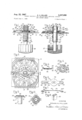
FIG. 1 is a side elevation of a rotary tap switch according to one embodiment of the invention, and shown in the normal contact or current conducting position;
3,337,699 Patented Aug. 22, 1967 FIG. 2 is a plan view;
FIG. 3 is a vertical sectional view taken along the line 33 of FIG. 2;
FIG. 4 is a side elevation of the index drive bar member;
FIG. 5 is a top plan view thereof;
FIG. 6 is a top plan view of the contact blade;
FIG. 7 is a side elevation thereof;
FIG. 8 is a perspective view of the pressure transmitting sleeve;
FIG. 9 is a side elevation of the bearing and index cam member;
FIG. 10 is a top plan view thereof;
FIG. 11 is a side elevation showing the contact blade in a lift-oft position;
FIG. 12 is a top plan view thereof;
FIG. 13 is a side elevation showing the contact blade in a fully disengaged position;
FIG. 14 is a top plan view thereof;
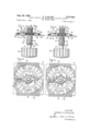
FIG. 15 is a side elevation of a modified form of the invention;
FIG. 16 is a top plan view thereof;
FIG. 17 is a vertical sectional view taken along the line 17-17 of FIG. 16;
FIG. 18 is a top plan view of the ball carrier employed in the modification of FIG. 15;
FIG. 19 is a side elevation thereof;
FIG. 20 is a top plan view of the index drive bar member;
FIG. 21 is a side elevation thereof;
FIG. 22 is a top plan view of the contact blade;
FIG. 23 is a side elevation thereof;
FIG. 24 is a side elevation of the bearing and index cam member; and
FIG. 25 is a top plan view thereof.
Referring to the drawings, and more particularly to FIGS. l-14, the rotary electric tap switch according to the exemplary embodiment of the invention illustrated therein comprises a printed circuit board 10, formed of phenolic or other suitable dielectric material and provided substantially centrally with a circular opening 11. In concentric relation to the opening 11 there is provided a first circumferential series of contact pads 12, joined together by a circular ring 13, and connected by a cur rent conducting lead 14 extending outwardly from one of the pads 12 with a connector 15 secured upon one edge of the board. In outwardly spaced concentric relation to the series of pads 12, there i provided a second circumferential series of contact pads 16 in radial alignment with the pads 12 and individually connected by current conducting leads 17 to connectors 18 secured upon opposite edges of the board, half of the pads preferably being connected to connectors provided along one edge of the board and the other half being connected to connect ors provided along the opposite edge. The pads and current conducting leads are of copper foil deposited upon the board 10 by methods well known in the art of printed circuit boards and the connectors are preferably clipped upon the board edges in current conducting contact with the leads.
A bearing and index cam member 19, shown in detached relation in FIGS. 9 and 10, is mounted upon the peak of each index corrugations is in radial line with the the board the radial center line of a respective contact pad 16. The sleeve 20 is of smaller diameter than the opening 11 and the index flange is of greater diameter, and in the assembled relation upon the board, the index flange is disposed at the upper side of the board with its outer periphcry in outwardly spaced concentric relation to the opening wall, while the sleeve 20 is disposed in concentric relation within the opening 11 in inwardly spaced relation to the opening wall. The bearing and index member 19 is secured to the board by integral outwardly offset lugs 23 projecting downwardly from the edge of the flange 21, which are engaged downwardly through slots 24 provided in the board in the dot-and-dash line position shown in FIG. 9 and are thereupon bent outwardly against the underside of the board as clearly seen in FIG. 3.
An actuating shaft 25 is fitted within the sleeve 20 for rotary and sliding movement therein, one end of the shaft extending below the sleeve and having engaged thereon a thumb-knob .26 formed of suitable dielectric material and secured to the shaft by a set screw 27, while the other end of the shaft extends above the index flange and is provided with flat faces 28-28 at its opposite sides for the purpose of keying certain parts of the switch thereto, as will presently more fully appear.
In normally spaced relation below the lower end of the sleeve 20 the shaft is provided with an abutment washer 29 disposed against a split spring ring 30 having snap engagement in an annular groove 31 of the shaft, and between the washer 29 and the underside of the index flange 21 there is disposed about the sleeve 20 a helical expansion spring 32 normally exerting downward pressure upon the shaft.
An index drive bar member 33, illustrated in detached relation in FIGS. 4 and 5, is keyed upon the shaft 25 and for this purpose is provided with a central circular disc portion 34 having a shaft engaging opening 35 corresponding in shape to the cross-sectional shape of the upper flat-sided end portion of the shaft. In concentric surrounding relation to the disc portion 34 there is provided an annular series of radially disposed index corrugations 36 which in the normal position have fitting complementary engagement at their underside with the upper side of the index cam corrugations 22.
A sleeve 37, shown in detached relation in FIG. 8, having a bore corresponding to the cross-sectional shape of the upper flat-sided end portion of the shaft, is engaged in keyed relation upon the shaft, with its lower end hearing upon the upper side of the disc portion 34 of the index drive bar member, and with its upper end engaged with an abutment washer 38 engaged upon the upper end portion of the shaft and retained thereon by a split spring ring 39 having snap engagement in an annular groove 40 in the shaft. The assembly is such that the spring 32 in exerting downward pressure upon the shaft 25 also exerts downward pressure upon the index drive bar member through the washer 38 and the sleeve 37, to thus press the index corrugations 36 into engagement with the index cam corrugations 22. The spacing of the lower end of the sleeve 20 from the abutment ring 29 permits limited upward sliding movement of the shaft in the sleeve 20, so that upon turning the shaft through the thumb-knob 26 the index drive bar is intermittently raised and lowered as the index corrugations 36 ride in step-by-step sequence over the index cam corrugations 22.
Associated with the index drive bar is a contact blade member 41, shown in detached relation in FIGS. 6 and 7, which comprises an intermediate disc portion 42 provided with a noncircular opening 43, corresponding in shape to the external shape of the sleeve 37 with which it is slidably engaged. An arm 44 extends radially outwardly from the disc portion 42 at one side and is provided at its outer end with a contact button 45 normally engaged with one of the contact pads 16, while at the opposite side there is provided a relatively shorter arm 46 provided at its outer end with a contact button 47, which normally engages one of the contact pads 12 in diametric line with the contact pad 16 engaged by the button 45. The arm 44 is provided with a downwardly inclined intermediate portion 48, preferably provided with an embossed stiffening rib 49 and the arm 46 is provided with an intermediate offset bend 46% The outer ends of the arms are thus downwardly offset from the intermediate disc portion 42,
The arm 44 is positioned within a channel shaped extension 50 at one side of the index drive bar having a pair of lugs 51 extended inwardly over the arm 44, and similarly the arm 46 is positioned within a channel extension 52 at the opposite side having a pair of lugs 53 extending over the arm 46. The upward spacing of the lugs 51 and 53 from the base walls of the extensions 50 and 52 is such as to permit of limited relative vertical movement between the index drive bar and the contact blade member during the indexing operation, as will presently more fully appear. Interposed between the upper side of the inter-mediate disc portion 42 of the contact blade member and the abutment washer 38 is a helical expansion spring 54, the expansive pressure of which is substantially less than that of the spring 32. The relationship of the two springs to the contact blade is such that during each indexing cycle there is a differential spring pressure applied to the contact blade whereby in the normal contact position the relatively greater pressure of the spring 32 is exerted to maintain the contact buttons in firm relation with the contact pads, while in the transitory movement during indexing from one station to the next the relatively strong pressure of the spring 32 is diverted while the relatively lighter pressure of the spring 54 takes over, so that as the contact buttons are moved out of full contacting position, they are in wiping contact with the pads under gradually decreasing pressure, thus providing a lingering, self-cleaning rubbing contact free from arcing. Conversely, as the contact buttons move into full contacting position, they engage the pads under gradually increasing pressure.
The operation of the switch during indexing is illustrated in FIGS. 11-14 in comparison with the normal full contact position of the switch illustrated in FIGS. 1-3.
As seeen in FIGS. 1-3 illustrating the full contact position of the switch, the index drive bar member 33 is in full nesting engagement with the index cam member 22 under the pressure of the spring 32, which normally exerts a downward force upon the shaft 25 and through the washer 38 and sleeve 37 transmits such downward force upon the index drive bar member. At the same time the lugs 51 and 53 are in engagement with the upper side of the contact blade 41 and, by virtue of the fact that the downward pressure of the spring 54 upon the contact blade is substantially lighter than that of spring 32, the pressure of the stronger spring 32 is exerted through the lugs 51 and 53 directly upon the contact blade to maintain the contact buttons 45 and 47 in firm contact relation with the respective contact pads 16 and 12.
As the switch is indexed to the next station by turning the thumb knob 27, the corrugations of the index drive bar 33 first ride up upon the inclined faces of the corrugations of the index cam 22 as seen in FIG. 11, causing the lugs 51 and 53 to move upwardly out of engagement with the contact blade member 41, so that the relatively stronger pressure of the spring 32 is diverted from the contact blade and at the same time the relatively lighter pressure of the spring 54 is exerted thereon. Thus as the contact buttons move from the full contact position as seen in FIGS. 1-3, they remain in contact with the contact pads but with substantially reduced spring pressure, so that the disengagement is through a smooth wiping contact action under gradually decreasing pressure to the point where the index drive bar member reaches its fully raised position as seen in FIG. 13, where the contact buttons are at the intermediate point between adjacent contact pads, and where the contact blade member is pressed against the bottom walls of the channel portions 50 and 52 of the index drive bar member under the pressure of the spring 54.
As the switch is moved from the position as seen in FIGS. 13 and 14 to the next station, the contact buttons are gradually lowered and engage the contact pads with a smooth wiping action under pressure of the spring 54, with the pressure gradually increasing as the index drive bar member is lowered into full nesting engagement with the cam index member 22, at which point the lugs 51 and 53 engage the contact blade under the relatively greater pressure of the spring 32.
In FIGS. 15-25, there is illustrated a modified form of the invention comprising a circular base 55 formed of suitable dielectric insulating material and provided near its outer periphery with a circumferential series of raised contacts 56, each preferably secured by swedging a stud projecting '57 within a hole 58 in the base, with an apertured terminal connector 59 interposed beneath the contact, and projecting beyond the periphery of the base. An even number of contacts 56 are provided in equally spaced relation, so that diametrically opposite contacts are adapted to be connected in the same circuit, such circuit being closed by a current conducting contact blade connected between the diametrically opposite contacts, as will presently more fully appear. While four such contacts are illustrated, it will be understood that any desired even number of contacts may be provided.
A circular opening 60 is provided centrally of the base 55 in which there is engaged a cam bushing member 61 comprising a cylindrical tubular bearing bushing 62 projecting downwardly from the base, and provided at its upper end with a flange 63 engaged with the upper side of the base and secured thereto by downwardly projecting lugs 64 at its periphery engaged in slots 65 in the base and bent over inwardly against the underside of the base.
The flange constitutes an indexing cam and for this purpose is provided with a plurality of circular socket holes 66, corresponding in number to and radially aligned with the contacts 56, each said hole being provided at opposite sides with radially disposed cam projections 67 and 68, preferably in the form of embossed ribs convexly curved in cross section so as to provide inclined entrance and exit cam surfaces in relation to the holes.
An actuating shaft 69 is rotatably fitted within the bushing 62, one end of the shaft extending below the bushing and having engaged thereon a thumb knob 70 formed of suitable dielectric material and secured by a set screw 71, while the other end extends above the flange 63 and is provided with flat faces 72-72 at its opposite sides, for the purpose of keying certain parts of the switch thereto, as will presently more fully appear. In order to restrain the shaft against upward movement in the bushing 62 a split spring ring 73 having snap engagement in an annular groove 74 in the shaft is engaged with the lower end of the bushing.
Upon the upper end of the shaft 69 there is provided an abutment washer 75 having an aperture 76 corresponding in shape to the cross-sectional shape of the upper fiatted portion of the shaft, whereby the washer is non-rotatably engaged with the shaft, being retained in place by a split spring ring 77 engaged in an annular groove 78 in the shaft.
A ball drive bar 79, shown in detail in FIGS. 18 and 19, is provided centrally with an aperture 80 corresponding in shape to the cross-sectional shape of the flatted portion of the shaft, whereby the bar has keyed axially sliding engagement with the shaft. In diametrically aligned relation at each side of the aperture 80 the bar is provided with a pair of upwardly extending cylindrical flanges 81-81 providing tubular retainers for a pair of index balls 82-82, which normally seat in the pair of diametrically opposite socket holes 66-66 of the cam flange 63, and which through turning of the shaft as the switch is moved from one station tothe next are adapted to be raised from the socket holes through riding up the cam ribs 67 and to be lowered into the socket holes through riding down the cam ribs 68.
A contact blade drive bar 84, shown in detail in FIGS. 20 and 21, is provided centrally with an aperture 85 corresponding in shape to the cross-sectional shape of the flatted end of the shaft 69 and has keyed sliding engagement therewith. The drive bar is supported upon the pair of index balls 82-82 and is provided along its longitudinal edges with positioning flanges 86-86, between which are engaged the tubular flanges 81-81 of the ball drive bar 79. The ball drive bar and the contact blade drive bar thus keyed together for rotation with the shaft 69.
A helical spring 87 is disposed in surrounding relation to the upper end portion of the shaft 69 beneath the abutment washer 75 and exerts downward pressure uponthe contact blade drive bar 84, which in turn exerts downward pressure upon the balls 83 to normally seat them in the socket holes 66. Thus, as the shaft 69 is turned to index the switch, the balls 82 rise out of seating engagement in the holes 66, causing the contact drive bar to be raised against the pressure of the spring 87.
A contact blade member 88, shown in detail in FIGS. 22 and 23, is keyed to the contact drive bar 84, as will presently more fully appear, and comprises an intermediate ring shaped portion 89 having an upwardly extending circular rim 90 at its inner edge, and a pair of radially extending arms 9191 having cont-act buttons 9292 secured upon their outer ends for contact wtih a pair of diametrically opposite contacts 57 of the base 56. Each contact button is secured by a riveted stud 93 engaged in a hole 94 in the base and its lower contact face 95 is preferably convexly curved.
At each end of the contact blade drive bar 84 there is provided a pair of angular lugs 9696 engaged with the side edges of the arms 91 of the contact blade and extended inwardly over the upper surface thereof, the I spacing of the lugs from the upper surface of the contact drive bar 84 being such that in the normal contacting position, as seen in FIG. 17, the underside of the Icjontact blade is raised from the upper side of the drive A helical compression spring 97 is interposed between the abutment Washer 75 and the upper side of the intermediate ring portion 89 of the contact blade with the circular flange 90 interposed between the lower end of the spring 97 and the lower end of the spring 87. The spring 87 is a substantially heavier spring than the spring 97 and exerts a substantially greater force. Consequently, in the operative contact position of the switch as seen in FIG. 17 the force of the spring 87, in addition to pressing the contact blade drive bar and the index balls downwardly, exerts its downward force upon the contact blade through the engagement of the lugs 96 with its upper side, so that the full force of the spring 87 is eflfective to maintain the contacts in engagement. As the switch is indexed from one station to the next, the raising of the balls and the contact blade drive bar causes the lugs 96 to move upwardly away from the contact blade, whereupon the pressure of the spring 97 becomes elfective to press the contacts into contacting engagement with gradually decreasing pressure as the switch is moved from one station to the next. As the switch is moved into contact position the relatively lighter force of the spring 97 is exerted upon the contacts up to the full contact point, whereupon the lugs 96 engage the upper side of the contact blade and the greater pressure of the spring 87 is exerted thereon.
Having described my invention, what I claim and desire to secure by Letters Patent is:
1. A rotary electric tap switch comprising a base, a shaft supported for rotation on said base having its axis normal to the plane of said base, fixed contact means carried upon said base in concentric relation to said shaft axis, a contact member arranged for rotation about said shaft axis and including movable contact means movable with said contact member for engagement with and disengagement from said fixed contact means, drive means for said contact member keyed to said shaft for rotation therewith, index means connecting said contact member to said drive means for rotation therewith and for raising and lowering movement of said contact means relative to said drive means, detent indexing means carried by said base for imparting raising and lowering movement to said drive means and for positioning said movable contact means in normal full contact position in engagement with said fixed contact means in a lowered position of said drive means, and differential spring means arranged to exert pressure upon said drive means to press said movable contact means downwardly into engagement with said fixed contact means in said lowered position of said drive means and to exert gradually increased and gradually decreased downward pressure upon said contact member in a raised position of said drive means as said movable contact means is respectively moved into and out of said normal full contact position.
2. A rotary electric tap switch as defined in claim 1, further characterized by a shaft receiving opening in said base, a bearing sleeve disposed in said opening extending downwardly from said base and having an annular flange engaged with the upper side of said base, said flange including index formations constituting said index means.
3. A rotary electric tap switch as defined in claim 1, wherein said shaft has raising and lowering movement with said drive means.
4. A rotary electric tap switch as defined in claim 1, wherein said drive means has raising and lowering movement relatively to said shaft.
5. A rotary tap switch as defined in claim 1, wherein abutment means carried by said drive means is engaged with said contact member in a lowered position of said drive means and disengaged therefrom in a raised position of said drive means.
6. A rotary electric tap switch as defined in claim 1, wherein said differential spring means comprises a first helical expansion spring arranged to exert downward pressure upon said drive means, and a second helical expansion spring having less expansive force than said first spring and arranged to exert downward pressure upon said contact member in a raised position of said drive means.
7. A rotary electric tap switch as defined in claim 6, wherein said first spring is interposed between said base and said shaft to exert downward pressure upon said shaft and said drive means, and said second spring is interposed between said shaft and said contact member to exert downward pressure thereon in a raised position of said drive means.
8. A rotary tap switch as defined in claim 7 wherein said contact member has an opening through which said shaft is engaged and includes a pair of radially extending arms, and wherein said movable contact means is carried by said arms.
9. A rotary electric tap switch as defined in claim 8, further characterized by a sleeve interposed between said shaft and said drive means and engaged for relative axial movement in said opening of said contact member, whereby downward pressure upon said shaft is transmitted to said drive means. i
10. A rotary electric tap switch as defined in claim 6, wherein said drive means has raising and lowering movement relatively to said shaft, wherein said first spring is interposed between said shaft and the upper side of said drive means, and wherein said second spring is interposed between said shaft and the upper side of said contact member.
11. A rotary tap switch as defined in claim 10, wherein said second spring is in surrounding relation to said first spring, and wherein said contact member has a shaft receiving opening defined by a cylindrical rim flange disposed outwardly of said first spring and inwardly of said second spring.
References Cited UNITED STATES PATENTS 2,127,608 8/1938 Manley 200- 1123 3,005,882 10/1961 White 2001'1.1l
ROBERT K. SCHAEFER, Primary Examiner.
I. R. SCOTT, Assistant Examiner.
Claims (1)
1. A ROTARY ELECTRIC TAP SWITCH COMPRISING A BASE, A SHAFT SUPPORTED FOR ROTATION ON SAID BASE HAVING ITS AXIS NORMAL TO THE PLANE OF SAID BASE, FIXED CONTACT MEANS CARRIED UPON SAID BASE IN CONCENTRIC RELATION TO SAID SHAFT AXIS, A CONTACT MEMBER ARRANGED FOR ROTATION ABOUT SAID SHAFT AXIS AND INCLUDING MOVABLE CONTACT MEANS MOVABLE WITH SAID CONTACT MEMBER FOR ENGAGEMENT WITH AND DISENGAGEMENT FROM SAID FIXED CONTACT MEANS, DRIVE MEANS FOR SAID CONTACT MEMBER KEYED TO SAID SHAFT FOR ROTATION THEREWITH, INDEX MEANS CONNECTING SIAD CONTACT MEMBER TO SAID DRIVE MEANS FOR ROTATION THEREWITH AND FOR RAISING AND LOWERING MOVEMENT OF SAID CONTACT MEANS RELATIVE TO SAID DRIVE MEANS, DETENT INDEXING MEANS CARRIED BY SAID BASE FOR IMPARTING RAISING AND LOWERING MOVEMENT OF SAID DRIVE MEANS AND FOR POSITIONING SAID MOVABLE CONTACT MEANS IN NORMAL FULL CONTACT POSITION
Priority Applications (1)
| Application Number | Priority Date | Filing Date | Title |
|---|---|---|---|
| US556335A US3337699A (en) | 1966-06-09 | 1966-06-09 | Rotary electric tap switch with improved contact and detent means |
Applications Claiming Priority (1)
| Application Number | Priority Date | Filing Date | Title |
|---|---|---|---|
| US556335A US3337699A (en) | 1966-06-09 | 1966-06-09 | Rotary electric tap switch with improved contact and detent means |
Publications (1)
| Publication Number | Publication Date |
|---|---|
| US3337699A true US3337699A (en) | 1967-08-22 |
Family
ID=24220909
Family Applications (1)
| Application Number | Title | Priority Date | Filing Date |
|---|---|---|---|
| US556335A Expired - Lifetime US3337699A (en) | 1966-06-09 | 1966-06-09 | Rotary electric tap switch with improved contact and detent means |
Country Status (1)
| Country | Link |
|---|---|
| US (1) | US3337699A (en) |
Cited By (5)
| Publication number | Priority date | Publication date | Assignee | Title |
|---|---|---|---|---|
| US3466254A (en) * | 1967-11-20 | 1969-09-09 | Collins Radio Co | Three position rf circuit rotary switch |
| US4538036A (en) * | 1982-05-18 | 1985-08-27 | Caterpillar Tractor Co. | Electrical switching apparatus |
| EP0223968A3 (en) * | 1985-10-30 | 1989-06-14 | Braun Aktiengesellschaft | Rotating electrical switch |
| DE4216101C1 (en) * | 1992-05-15 | 1993-06-24 | Leonhardy Gmbh, 8561 Reichenschwand, De | Electrical rotary switch with multiple contact positions - has base with inset contact elements that are engaged by rotor coupled contact disc |
| FR2799303A1 (en) * | 1999-09-30 | 2001-04-06 | Valeo Electronique | ELECTRIC SWITCH FOR CONTROL PANEL, PARTICULARLY FOR MOTOR VEHICLE EQUIPMENT |
Citations (2)
| Publication number | Priority date | Publication date | Assignee | Title |
|---|---|---|---|---|
| US2127608A (en) * | 1934-11-06 | 1938-08-23 | Hugh H Eby Inc | Circuit controller |
| US3005882A (en) * | 1958-09-25 | 1961-10-24 | Westinghouse Electric Corp | Series-parallel switch |
-
1966
- 1966-06-09 US US556335A patent/US3337699A/en not_active Expired - Lifetime
Patent Citations (2)
| Publication number | Priority date | Publication date | Assignee | Title |
|---|---|---|---|---|
| US2127608A (en) * | 1934-11-06 | 1938-08-23 | Hugh H Eby Inc | Circuit controller |
| US3005882A (en) * | 1958-09-25 | 1961-10-24 | Westinghouse Electric Corp | Series-parallel switch |
Cited By (5)
| Publication number | Priority date | Publication date | Assignee | Title |
|---|---|---|---|---|
| US3466254A (en) * | 1967-11-20 | 1969-09-09 | Collins Radio Co | Three position rf circuit rotary switch |
| US4538036A (en) * | 1982-05-18 | 1985-08-27 | Caterpillar Tractor Co. | Electrical switching apparatus |
| EP0223968A3 (en) * | 1985-10-30 | 1989-06-14 | Braun Aktiengesellschaft | Rotating electrical switch |
| DE4216101C1 (en) * | 1992-05-15 | 1993-06-24 | Leonhardy Gmbh, 8561 Reichenschwand, De | Electrical rotary switch with multiple contact positions - has base with inset contact elements that are engaged by rotor coupled contact disc |
| FR2799303A1 (en) * | 1999-09-30 | 2001-04-06 | Valeo Electronique | ELECTRIC SWITCH FOR CONTROL PANEL, PARTICULARLY FOR MOTOR VEHICLE EQUIPMENT |
Similar Documents
| Publication | Publication Date | Title |
|---|---|---|
| US7132615B1 (en) | Switchpad for a pushbutton switch assembly | |
| GB1520899A (en) | Multiple switching apparatus | |
| US3337699A (en) | Rotary electric tap switch with improved contact and detent means | |
| US3196237A (en) | Rotary switch using plastic cover with integral leaf springs as positioning means | |
| US3350530A (en) | Switches for use with flexible printed circuits | |
| US3983355A (en) | Switching apparatus | |
| US1717057A (en) | Electric switch | |
| US4267412A (en) | Electrical switch | |
| US3015876A (en) | Method of making resilient switch contacts | |
| US2421983A (en) | Rotary selector switch | |
| US3478180A (en) | Rotary electric switch | |
| US2166803A (en) | Momentary contact push switch | |
| EP0390030A3 (en) | Horn switch mechanism of steering wheel | |
| CN217788258U (en) | Rotary switch | |
| US3226495A (en) | Rotary switch structure with saddleshaped insulator and two-legged contact brush | |
| US1080058A (en) | Switch. | |
| US4476360A (en) | Terminal seal for electric switch | |
| US3167852A (en) | Method of making an electrical switch | |
| US2883482A (en) | Printed circuit switch | |
| US1828059A (en) | Electric snap switch | |
| US2465213A (en) | Electric volume control | |
| JPH0421228Y2 (en) | ||
| EP0036263B1 (en) | Electrical switch | |
| US2454069A (en) | Electric socket construction | |
| CN214279819U (en) | Switch connector |