US3337860A - Display tracking system - Google Patents
Display tracking system Download PDFInfo
- Publication number
- US3337860A US3337860A US422844A US42284464A US3337860A US 3337860 A US3337860 A US 3337860A US 422844 A US422844 A US 422844A US 42284464 A US42284464 A US 42284464A US 3337860 A US3337860 A US 3337860A
- Authority
- US
- United States
- Prior art keywords
- pen
- character
- light
- transducer
- light pen
- Prior art date
- Legal status (The legal status is an assumption and is not a legal conclusion. Google has not performed a legal analysis and makes no representation as to the accuracy of the status listed.)
- Expired - Lifetime
Links
Images
Classifications
-
- G—PHYSICS
- G06—COMPUTING OR CALCULATING; COUNTING
- G06F—ELECTRIC DIGITAL DATA PROCESSING
- G06F3/00—Input arrangements for transferring data to be processed into a form capable of being handled by the computer; Output arrangements for transferring data from processing unit to output unit, e.g. interface arrangements
- G06F3/01—Input arrangements or combined input and output arrangements for interaction between user and computer
- G06F3/03—Arrangements for converting the position or the displacement of a member into a coded form
- G06F3/033—Pointing devices displaced or positioned by the user, e.g. mice, trackballs, pens or joysticks; Accessories therefor
- G06F3/038—Control and interface arrangements therefor, e.g. drivers or device-embedded control circuitry
- G06F3/0386—Control and interface arrangements therefor, e.g. drivers or device-embedded control circuitry for light pen
Definitions
- the present invention relates to display systems and techniques, and more particularly to a cathode ray tube display system for providing an indication of the position and speed of an associated light transducer.
- a lig-ht pen tracking or line following system which provides an indication of pen speed as well as direction.
- a special track character or marker symbol which may comprise an open rectangle with a dot in the center or a series of dots with a dot in the center portion thereof is employed.
- the size of the track character corresponds essentially to the circular field of view of the light pen. If the field of view of the pen is slightly d1splaced from the center of a tracking pattern, portions of the tracking character or marker pattern will be seen by the pen, the remainder will not.
- the particular portion of the marker character detected by the light pen dictates which direction to move the tracking pattern so as to follow the pen, assuming portions of the marker symbol remain within the field of view of the pen.
- information identifying the horizontal and vertical coordinate positions of the light pen are stored 1n digital form in pen position registers or counters.
- a certain displacement of the marker symbol will take place with respect to the field of view of the light pen depending on the pen velocity. This displacement is identified by output signals from the light pen as the marker symbol is continuously retraced.
- the tracking circuitry can update or move the marker symbol by a large increment using the digital technique of stepping a high order position or positions of the pen position registers during the time the pen is traveling at high velocity.
- the tracking pattern When the pen is traveling at low velocity, the tracking pattern will be updated in small increments by stepping the low order positions of the light pen registers. Thus, depending on the velocity of the light pen, either the low or high order of the position register will be stepped. By this means, the light pen is enabled to track at high or low speed without sacrificing precision, using a single logic implementation.
- the system in addition to providing an indication of light pen velocity, affords a substantial saving of display time in the tracking operation compared with known systems of the prior art.
- a primary object of the present invention to provide an improved light pen tracking system.
- Another object of the present invention is. to provide a high precision light pen tracking system utilizing digital techniques to generate the appropriate deflection signals for the associated cathode ray tube.
- Another object of the present invention is to provide an improved light pen tracking :system for providing an indication of pen position, direction and velocity.
- a further object of the present invention is to provide an improved display system'which provides coarse and line positioning of a special character on a CRT in accordance with the velocity of the light transducer.
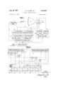
- FIGURE l illustrates in block form the overall light pen tracking system of the present invention.
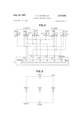
- FIGURE 2 illustrates in block logical form details of the comparator control circuit and pen position registers shown in block form in FIG. l.
- FIGURE 3 indicates in block logical form details Iof the stroke encoder shown in block form in FIGURE l.
- FIGURE 4 illustrates the digital coordinate addresses of the various portions of the marker pattern.
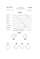
- FIGURE 5 illustrates a timing chart for operation of the system shown in FIGURE 1.
- FIGURE 6 illustrates the relationship between the marker pattern and the field of View of the pen with respect to various pen movements.
- the displacement of the light pen will vary in any given interval AT between position updatings.
- the tracking circuitry can step the tracking pattern by large increments while conversely when the pen is traveling at low velocity, the tracking pattern is updated by spacing the tracking pattern in small increments. At medium velocity, alternate groups of small and large steps occur.
- a substantial amount of time was required to continuously update the light pen, which time was not available for the actual display functions.
- This prior art system utilized approximately 40% ofthe available display time forV the light pen tracking function.
- the present invention by comparison utilizes only approximately 5% of the overall display time to provide the light pen function, while simultaneously providing a high or low velocity high precision tracking system.
- FIG- URE 6 two configurations of the marker symbol are shown with respect to the field of view of the light pen
- FIG. 6a one marker symbol comprising a series of live dots emenating from a centrally located dot
- the second symbol (FIG. 6b) comprising an open rectangular pattern with a dot at the center portion thereof.
- the field of view of the associated light transducer is identified by the circumscribed circle.
- the present invention will be described with respect to the dot conguration of FIG. 6a, although it will be understood by those skilled in the art t-hat various other forms of spatially oriented indicia could be readily substituted in the present invention.
- the special character is generated by cathode ray tube character generator means wherein the character is generated in a predetermined sequence or one stroke at a time.
- cathode ray tube character generator means wherein the character is generated in a predetermined sequence or one stroke at a time.
- One suitable CRT character generator for generating the special character is shown and described in copending application Ser. No. 90,678 now Pat. No. 3,248,725 entitled, Display System and Associated Method, filed by Paul R. Low et al., Feb. 21, 1961 and assigned to the assignee of the instant invention.
- the light pen effectively senses for the relative position of the character with respect to its field of view such that if the pen is not wholly centered over the character, the logic will be informed and take corrective action to place the character completely within the optical field of the light pen. As each of these light spots is generated or retraced, there is a blue liash visible to the light pen followed by a relatively yellow decay, the blue fiash causing the transducer to emit a pulse as each segment of the marker symbol is retraced. Thus the light pen is enabled to see a pseudo-portion of the special character at any given instant in time.
- the logic of the instant invention is based on the fact that each segment of the special character has a specific time slot assigned to it which may be logically ANDed to a time pulse generated during the intensification or re-intensification of that segment.
- one or more of the marker symbol component portions will be outside the field of view of the light pen and its detection initiates the tracking logic to move the character within the field of view of the pen, thereby simultaneously drawing a line on the screen of the CRT.
- the coarse or fine correction is determined by whether the center dot of the marker symbol is within or without the field of view of the transducer.
- FIGURE 1 there is illustrated in block logical form a pen tracking system in accordance with the present invention.
- a time pulse distributor 21 under control of oscillator applies sequential timing pulses via line 22 to a comparator control circuit shown as block 23, which receives as its second input the output from light pen 25 which is amplified by light pen amplifier 27 and applied through line 29.
- light pen 25 comprises a light transducer which is actuated by generation or re-generation of a spot on cathode ray tube 26 within its field of view and transmits a signal indicative of this spot to an output device, which, in the instant invention, comprises light pen amplifier 27.
- Light transducers in the form of light pens, pencils, guns, etc. are well known in the art, one example in the form of a light gun being shown in U.S. Patent No. 2,915,643 to R. G. Mork, issued Dec. 1, 1959 and entitled Light Gun Assembly.
- the operation of the light gun in the above referenced patent is identical to the light pen employed in the present invention, the only difference being in the specific physical configuration or package of the transducer.
- a signal designating the direction of light pen movement will be applied to the X position register 31 through lines 28, 30 and the Y position register 33 through lines 32, 34. Lines 28 and 34 are count up control lines, lines and 32 are count down control lines.
- Registers 31 and 33 are count up or count down counters which will effectively add or subtract a count in accordance with the pattern of the marker symbol ⁇ detected by the light pen. Such counters are considered conventional and well developed in the art so that the details have been omitted from the drawings in the interest of clarity. The details of the comparator control circuit and the manner in which signals indicative of the movement of the light pen are identified and acted upon are shown and described in further detail with respect to FIGURE 2. Effectively, the X and Y position counters or registers contain the digital quantities that ultimately control the position of the CRT electron beam. Therefore, by altering the X and Y quantities in accordance with the movement of the light pen, the X and Y position registers are stepped up or down according to the movement of the light pen.
- the outputs from the X and Y position registers 31 and 33 are applied to digital to analog decoders 35 and 37 respectively, wherein the digital signals are converted to corresponding analog signals and applied through lines 39 and 41 to the main positioning yoke 45.
- Digital to analog decoders 35 and 37 are preferably of the type shown and described in copending application Ser. No. 276,569 now Patent No. 3,290,671 Byte Decoder filed by William R. Lamoureux, Apr. 29, 1963 and assigned to the assignee of the instant invention.
- the output from time pulse distributor 21 is also applied via line 44 to stroke encoder 46. Stroke encoder 46, in combination with the timing pulse generator, generates the control signals for the five component dots of the marking symbol into the address form shown in FIGURE 4.
- the stroke encoder generates a series of signals for each of the marker symbol segments which are applied via lines 48A, 48B, 48C to the X character decoder 47 and via lines 50A, 50B and 50C to the Y character decoder 49.
- the X and Y character decoders 47 and 49 are conventional three bit digital to analog converters which essentially generate the appropriate X and Y character deflection signals to cause the component ⁇ segments of the track character to be continuously regenerated in a predetermined sequence and applied to the character positioning yoke 5l.
- the signals could be provided from a read only memory unit of the aforenoted copending application Ser. No.
- the CRT display system utilized in the preferred embodiment of the present invention utilizes two magnetic defiection yokes, a main positioning yoke 45 and a character positioning yoke 51, the main positioning yoke designating the area on the CRT where the marker symbol is to be displayed and the character deflection yoke generating the dot or stroke pattern of the marker symbol.
- the blank and unblank control circuitry utilized in the instant invention is assumed to be of conventional nature and has accordingly been omitted from the drawings in the interest of clarity.
- FIGURE 2 there is illustrated in detail the logical configuration of the comparator control circuit and associated X and Y position counters shown in block form in FIGURE 1.
- the output from light pen amplifier 27 is applied through line 29 to the first stage of a five stage shift register 55 which is shifted in sequence by lshift line 53.
- the specific shifting sequence is shown and fully described with reference to the timing diagram of FIGURE 5.
- the right and left most dots in the track character are defined as -l-X and -X respectively, the upper end lower vertical dots as -l-Y and -Y respectively, and the center dot is indicated as CD.
- the specific generation sequence employed in the present invention is -l-X and -X, -l-Y and followed by the cen'ter dot, the five signals being entered into shift register 55 and shifted by timing pulses TPI-TPS in that specific sequence.
- FIGURES 6c, d, e and f the two p potential increments of movement of the light pen with respect to the special track character, i.e., horizontal and vertical, are shown relative to the X and Y direction.
- the light pen has moved to the right but the center dot of the tracking character is still within the field of view of the pen.
- FIG. 6d it is seen that only the right most segment of the marker symbol (-l-X) is within the field of view of the light pen and the center dot is without.
- FIGURES 6e and 6f illustrate corresponding movements in the vertical direction. In the first instance (FIG.
- a low order position or a higher order position of the X position register will be stepped.
- logical AND circuit 83 is conditioned and the sampling signal on line 79' will provide an output to step the low order stage of the position register.
- logical AND circuit 81 is conditioned and the sampling signal on line 79 will pro vide an output on line 87 to step the fourth or 23 stage of the Y position register. The final determination of whether to step the counter up or down depends on which of the signals were Without the field of view of the light pen.
- FIGURE 3 there is illustrated the relative positioning and addressing scheme used to identify the component segments making up the tracking character.
- the character will be positioned at a particular location on the CRT screen by the main positioning yoke 45, the origin for the tracking character being arbitrarily defined as the lower left hand corner indicated as X and Y addresses of 000,000.
- the X component moves to the right as defined as positive, and vice-versa, while movements of the Y segments in the upward direction are also labeled positive -and vice-versa.
- the center dot is identified by X and Y addresses of 011,011.
- the -X segment is identified by X and Y addresses of 000,011, the -l-X segment is identified by addresses 111,011.
- the -l-Y segment is identied by X and Y addresses of 011,111 and the -Y segment is identified by addresses of 011,000 respectively.
- the -i-X and -X, the -i-Y and -Y and the center dot are continuously reintensified and detected in that particular sequence, although it will be appreciated that the particular Vsequence herein employed is purely a matter of design choice, the only requirement in the tracking operation herein described being that the marker symbol segments be continuously reintensified in some specified sequence whereby each of the segments has a specific time slot associated therewith.
- position coordinates contained in position registers 31 and 33 refer to the center element of the marker symbol, whose relative coordinates are shown to be 011,011. This offset of the origin of the lmarker symbol'from the indicated positioned coordinates in order to bring the center dot segment C.D. into correspondence with the indicated positional coordinates is accomplished in the preferred embodiment by applying -a negative current bias to the inputs of character yoke 51.
- the stroke encoder shown as block 46 in FIGURE 1.
- the basic function of the stroke encoder is to continuously regenerate signals representative of the X and Y addresses of each segment of the marker symbol in the heretofore prescribed sequence, the specific X and Y addresses for each of the segments being shown in FIGURE 3.
- the stroke encoder comprises a siX position time pulse distributor in which five of the timing pulses are used to encode three bit binary addresses signals indicative of the five segments of the marker symbol, whileV the sixth timing pulse is used to step the position registers.
- the time pulse distributor comprises a six stage timing ring which is closed upon itself by the reset line.
- a timing ring is a device which will generate timing pulses in a specific predetermined sequence, in the illustrated embodiment, sequencing from stages 1 6. Since the inputs to the character decoding circuits will be the -l-X, -X, +Y, -Y and center dot segments in that order, lines 108, 110, 112 and 114 and 116 are respectively associated with the indicated segments.
- the output from the stroke encoder is provided on lines 48A, 48B and 48C, 50A, 50B and y50C as broadly indicated in FIGURE l, from six associated logical OR circuits 101-111. As an example, referring to FIGURE 3, the X and Y addresses for the -I-X segment are 111,011.
- line 10S representative of the -l-X segment is 'connected to logical OR circuits 101, 103 and 109, 111 to generate the prescribed X and Y address signals.
- the center dot as a second example has an X and Y address of 011,011.
- Line 116 representative of the center segment is connected to logical OR circuits 163, 105 and 1139, 111 to provide the aforenoted address signals.
- each of the remaining three segment lines 110, 112 and 114 are connected to provide signals corresponding to the addresses indicated for the respective segments in FIGURE 3.
- the sixth output from the timing ring comprises the TF6 timing pulse used to step the respective X or Y register in the manner indicated and heretofore described with respect to FIG- URE 2. While a six position timing ring is shown in FIGURE 4, it is obvious that the number of stages will be directly related to the specific configuration of the marker symbol and the number of segments required to define the symbol so that a greater or lesser number of stages could readily be provided.
- FiGURE 5 there is illustrated a timing diagram to clarify the sequence of operation of certain of the elements heretofore described.
- Lines 1-5 in the timing diagram illustrate the signals used to generate the identified components of the marker symbol employed in the preferred embodiment of the invention. These signals terminate with their associated timing pulses TP1- TP5 but are initiated before the timing pulses to provide time for the character deflection yoke 51 to settle down.
- the TF6 timing pulse shown on line 6 of the timing diagram is that stepping pulse which controls the positioning of the X and Y position registers as shown and described relative to FIGURE 2.
- the reset comparator pulse on line 7 corresponds to the reset line 91 illustrated in FIG- URE 2.
- Timing pulses TF1-TPS are those generated by the initial five stages of timing ring 21 as illustrated in FIGURE 4.
- Timing pulses 1-5 are generated by the timing ring in FIGURE 4 and are utilized in the preferred embodiment of the invention to unblank the CRT beam at each of the segment positions of the marker symbol.
- the TF1 and 2 correspond to the -l-X and -X, TPS and 4 to the -l-Y and Y and TPS to the center dot CD.
- a display device including a light source
- each of said indicia elements in said symbol being generated in a predetermined timing sequence, an optical transducer, said transducer having a field of view adapted to encompass all of said indicia elements and generate response signals for detected indicia permutations,
- control logic responsive to the analysis of said detected indicia permutations for generating beam deection signals to modify the relative position of said indicia and said transducer to reposition said indicia in the field of view of said transducer.
- said means for modifying said beam deflection means comprises control means connected between said transducer and said beam deection means and wherein said detected indicia permutations vary in accordance with the motion of said light transducer.
- control logic means is responsive to the direction and velocity of said light transducer.
- control logic means includes a counter for each axis of said display, said counters being connected to said beam deflection means.
- An electro-optical system for generating a coordinate display under external control comprising in combination,
- a cathode ray tube having beam generation means, beam deflection -means and a screen
- said marker symbol comprising a plurality of indicia oriented in a predetermined coordinate display spatial relationship and generated in a predetermined time sequence
- transducer having a field of View adapted to detect said spatially oriented indicia permutations in accordance with the direction of motion of said transducer, and control means responsive to the permutation and time sequence of marker indicia detected by said light transducer for generating correction signals to modify said beam defiection means to enable said beam to follow the motion of said transducer.
- control means comprises a logical configuration adapted to automatically generate appropriate correction signals in response to selective permutations of said marker indicia.
- control means is adapted to generate coarse or ne deection increments in accordance with the velocity of said light transducer.
Landscapes
- Engineering & Computer Science (AREA)
- General Engineering & Computer Science (AREA)
- Theoretical Computer Science (AREA)
- Human Computer Interaction (AREA)
- Physics & Mathematics (AREA)
- General Physics & Mathematics (AREA)
- Position Input By Displaying (AREA)
Priority Applications (7)
| Application Number | Priority Date | Filing Date | Title |
|---|---|---|---|
| US422844A US3337860A (en) | 1964-12-31 | 1964-12-31 | Display tracking system |
| FR42304A FR1466593A (fr) | 1964-12-31 | 1965-12-15 | Système d'affichage |
| GB53161/65A GB1086699A (en) | 1964-12-31 | 1965-12-15 | Improvements in or relating to cathode ray tube systems |
| DEJ29720A DE1261159B (de) | 1964-12-31 | 1965-12-24 | Verfahren zum Nachfuehren eines Leuchtflecks auf einem als Schreibebene dienenden Bildschirm einer Kathodenstrahlroehre und Anordnung zur Durchfuehrung des Verfahrens |
| NL656517116A NL151528B (nl) | 1964-12-31 | 1965-12-29 | Inrichting voor het volgen van bewegingen van een lichtpen. |
| CH1803065A CH445558A (de) | 1964-12-31 | 1965-12-29 | Verfahren zur Erzeugung einer Schreibspur auf dem Bildschirm einer Kathodenstrahlröhre mit Hilfe eines Griffels und Anordnung zur Ausführung des Verfahrens |
| SE16875/65A SE318735B (de) | 1964-12-31 | 1965-12-29 |
Applications Claiming Priority (1)
| Application Number | Priority Date | Filing Date | Title |
|---|---|---|---|
| US422844A US3337860A (en) | 1964-12-31 | 1964-12-31 | Display tracking system |
Publications (1)
| Publication Number | Publication Date |
|---|---|
| US3337860A true US3337860A (en) | 1967-08-22 |
Family
ID=23676654
Family Applications (1)
| Application Number | Title | Priority Date | Filing Date |
|---|---|---|---|
| US422844A Expired - Lifetime US3337860A (en) | 1964-12-31 | 1964-12-31 | Display tracking system |
Country Status (7)
| Country | Link |
|---|---|
| US (1) | US3337860A (de) |
| CH (1) | CH445558A (de) |
| DE (1) | DE1261159B (de) |
| FR (1) | FR1466593A (de) |
| GB (1) | GB1086699A (de) |
| NL (1) | NL151528B (de) |
| SE (1) | SE318735B (de) |
Cited By (30)
| Publication number | Priority date | Publication date | Assignee | Title |
|---|---|---|---|---|
| US3394366A (en) * | 1965-04-08 | 1968-07-23 | Bendix Corp | Data display system |
| US3413515A (en) * | 1966-04-29 | 1968-11-26 | Massachusetts Inst Technology | Electron beam position sensor |
| US3440638A (en) * | 1965-04-08 | 1969-04-22 | Bendix Corp | Data display system with lateral photocell for digital repositioning of displayed data |
| US3459926A (en) * | 1965-10-18 | 1969-08-05 | Ibm | Graphic vector generator |
| US3474438A (en) * | 1965-09-30 | 1969-10-21 | Monsanto Co | Display system |
| US3492657A (en) * | 1967-07-17 | 1970-01-27 | Lockheed Aircraft Corp | Light sensitive detector and time-correlated generator |
| US3493732A (en) * | 1965-11-09 | 1970-02-03 | Ibm | Digital positioner |
| US3505666A (en) * | 1966-10-03 | 1970-04-07 | Ibm | Tracking light pen |
| US3505561A (en) * | 1967-02-14 | 1970-04-07 | Massachusetts Inst Technology | Analog pen tracking on a cathode ray tube display device |
| US3506875A (en) * | 1967-06-28 | 1970-04-14 | Hitachi Ltd | Pen-tracking system in cathode-ray tube display equipment |
| US3509350A (en) * | 1966-10-17 | 1970-04-28 | Ibm | Light pen detection verification display system |
| US3509542A (en) * | 1967-08-15 | 1970-04-28 | Sperry Rand Corp | Digital vector generator |
| US3510634A (en) * | 1966-08-01 | 1970-05-05 | Sperry Rand Corp | Digital vector generator |
| US3543240A (en) * | 1968-05-06 | 1970-11-24 | Rca Corp | Light pen operating with remote graphic display |
| US3576574A (en) * | 1968-01-15 | 1971-04-27 | Ibm | Light pen tracking unit with alternative tracking patterns |
| US3581302A (en) * | 1968-03-04 | 1971-05-25 | Harris Intertype Corp | Apparatus and method for providing graphical configurations by sequentially directing a radiant energy beam to present image positions |
| US3671668A (en) * | 1968-11-18 | 1972-06-20 | Leonard Reiffel | Teaching system employing a television receiver |
| US3680078A (en) * | 1969-12-23 | 1972-07-25 | Ibm | Light pen arrangement for providing three degrees of freedom for a light pen in an interactive graphics system |
| US3739347A (en) * | 1970-03-20 | 1973-06-12 | Tektronix Inc | Cursor for use in performing graphic input in a display |
| US3786479A (en) * | 1968-12-09 | 1974-01-15 | Ibm | Video display system |
| US3877018A (en) * | 1973-02-22 | 1975-04-08 | Mitsui Shipbuilding Eng | Shift register display for light pen |
| US3944988A (en) * | 1969-11-21 | 1976-03-16 | Compagnie Internationale Pour L'informatique - C.I.I. | Image-display system interacting with light pen |
| US3995269A (en) * | 1974-11-29 | 1976-11-30 | Sanders Associates, Inc. | Alignment of a video display system having multiple inputs |
| US4277783A (en) * | 1979-07-02 | 1981-07-07 | Bell Telephone Laboratories, Incorporated | Light pen tracking method and apparatus |
| US4386349A (en) * | 1981-04-28 | 1983-05-31 | Sperry Corporation | High resolution graphics smoothing |
| US4434502A (en) | 1981-04-03 | 1984-02-28 | Nippon Electric Co., Ltd. | Memory system handling a plurality of bits as a unit to be processed |
| US4949079A (en) * | 1985-04-19 | 1990-08-14 | Hugh Loebner | Brightpen/pad graphic device for computer inputs and the like |
| US5073770A (en) * | 1985-04-19 | 1991-12-17 | Lowbner Hugh G | Brightpen/pad II |
| US5159322A (en) * | 1985-04-19 | 1992-10-27 | Loebner Hugh G | Apparatus to digitize graphic and scenic information and to determine the position of a stylus for input into a computer or the like |
| USRE36455E (en) * | 1985-04-19 | 1999-12-21 | Loebner; Hugh | Brightpen/pad II |
Families Citing this family (1)
| Publication number | Priority date | Publication date | Assignee | Title |
|---|---|---|---|---|
| ES518799A0 (es) * | 1982-01-06 | 1984-06-16 | Bradley Milton Co | Un aparato presentador de video, particularmente destinado a utilizarse en un juego. |
Citations (4)
| Publication number | Priority date | Publication date | Assignee | Title |
|---|---|---|---|---|
| US2553245A (en) * | 1946-06-04 | 1951-05-15 | Bell Telephone Labor Inc | Electronic tracing system |
| US3037192A (en) * | 1957-12-27 | 1962-05-29 | Research Corp | Data processing system |
| US3089918A (en) * | 1960-09-09 | 1963-05-14 | Bell Telephone Labor Inc | Telewriting apparatus |
| US3229100A (en) * | 1962-12-31 | 1966-01-11 | Ibm | Electronic servo system |
-
1964
- 1964-12-31 US US422844A patent/US3337860A/en not_active Expired - Lifetime
-
1965
- 1965-12-15 GB GB53161/65A patent/GB1086699A/en not_active Expired
- 1965-12-15 FR FR42304A patent/FR1466593A/fr not_active Expired
- 1965-12-24 DE DEJ29720A patent/DE1261159B/de not_active Withdrawn
- 1965-12-29 SE SE16875/65A patent/SE318735B/xx unknown
- 1965-12-29 CH CH1803065A patent/CH445558A/de unknown
- 1965-12-29 NL NL656517116A patent/NL151528B/xx not_active IP Right Cessation
Patent Citations (4)
| Publication number | Priority date | Publication date | Assignee | Title |
|---|---|---|---|---|
| US2553245A (en) * | 1946-06-04 | 1951-05-15 | Bell Telephone Labor Inc | Electronic tracing system |
| US3037192A (en) * | 1957-12-27 | 1962-05-29 | Research Corp | Data processing system |
| US3089918A (en) * | 1960-09-09 | 1963-05-14 | Bell Telephone Labor Inc | Telewriting apparatus |
| US3229100A (en) * | 1962-12-31 | 1966-01-11 | Ibm | Electronic servo system |
Cited By (31)
| Publication number | Priority date | Publication date | Assignee | Title |
|---|---|---|---|---|
| US3394366A (en) * | 1965-04-08 | 1968-07-23 | Bendix Corp | Data display system |
| US3440638A (en) * | 1965-04-08 | 1969-04-22 | Bendix Corp | Data display system with lateral photocell for digital repositioning of displayed data |
| US3474438A (en) * | 1965-09-30 | 1969-10-21 | Monsanto Co | Display system |
| US3459926A (en) * | 1965-10-18 | 1969-08-05 | Ibm | Graphic vector generator |
| US3493732A (en) * | 1965-11-09 | 1970-02-03 | Ibm | Digital positioner |
| US3413515A (en) * | 1966-04-29 | 1968-11-26 | Massachusetts Inst Technology | Electron beam position sensor |
| US3510634A (en) * | 1966-08-01 | 1970-05-05 | Sperry Rand Corp | Digital vector generator |
| US3505666A (en) * | 1966-10-03 | 1970-04-07 | Ibm | Tracking light pen |
| US3509350A (en) * | 1966-10-17 | 1970-04-28 | Ibm | Light pen detection verification display system |
| US3505561A (en) * | 1967-02-14 | 1970-04-07 | Massachusetts Inst Technology | Analog pen tracking on a cathode ray tube display device |
| US3506875A (en) * | 1967-06-28 | 1970-04-14 | Hitachi Ltd | Pen-tracking system in cathode-ray tube display equipment |
| US3492657A (en) * | 1967-07-17 | 1970-01-27 | Lockheed Aircraft Corp | Light sensitive detector and time-correlated generator |
| US3509542A (en) * | 1967-08-15 | 1970-04-28 | Sperry Rand Corp | Digital vector generator |
| US3576574A (en) * | 1968-01-15 | 1971-04-27 | Ibm | Light pen tracking unit with alternative tracking patterns |
| US3581302A (en) * | 1968-03-04 | 1971-05-25 | Harris Intertype Corp | Apparatus and method for providing graphical configurations by sequentially directing a radiant energy beam to present image positions |
| US3543240A (en) * | 1968-05-06 | 1970-11-24 | Rca Corp | Light pen operating with remote graphic display |
| US3671668A (en) * | 1968-11-18 | 1972-06-20 | Leonard Reiffel | Teaching system employing a television receiver |
| US3786479A (en) * | 1968-12-09 | 1974-01-15 | Ibm | Video display system |
| US3944988A (en) * | 1969-11-21 | 1976-03-16 | Compagnie Internationale Pour L'informatique - C.I.I. | Image-display system interacting with light pen |
| US3680078A (en) * | 1969-12-23 | 1972-07-25 | Ibm | Light pen arrangement for providing three degrees of freedom for a light pen in an interactive graphics system |
| US3739347A (en) * | 1970-03-20 | 1973-06-12 | Tektronix Inc | Cursor for use in performing graphic input in a display |
| US3877018A (en) * | 1973-02-22 | 1975-04-08 | Mitsui Shipbuilding Eng | Shift register display for light pen |
| US3995269A (en) * | 1974-11-29 | 1976-11-30 | Sanders Associates, Inc. | Alignment of a video display system having multiple inputs |
| US4277783A (en) * | 1979-07-02 | 1981-07-07 | Bell Telephone Laboratories, Incorporated | Light pen tracking method and apparatus |
| US4434502A (en) | 1981-04-03 | 1984-02-28 | Nippon Electric Co., Ltd. | Memory system handling a plurality of bits as a unit to be processed |
| US4386349A (en) * | 1981-04-28 | 1983-05-31 | Sperry Corporation | High resolution graphics smoothing |
| US4949079A (en) * | 1985-04-19 | 1990-08-14 | Hugh Loebner | Brightpen/pad graphic device for computer inputs and the like |
| US5073770A (en) * | 1985-04-19 | 1991-12-17 | Lowbner Hugh G | Brightpen/pad II |
| US5159322A (en) * | 1985-04-19 | 1992-10-27 | Loebner Hugh G | Apparatus to digitize graphic and scenic information and to determine the position of a stylus for input into a computer or the like |
| USRE36455E (en) * | 1985-04-19 | 1999-12-21 | Loebner; Hugh | Brightpen/pad II |
| WO1993003474A1 (en) * | 1991-08-02 | 1993-02-18 | Hugh Loebner | Apparatus to digitize graphic and scenic information and determine stylus position |
Also Published As
| Publication number | Publication date |
|---|---|
| FR1466593A (fr) | 1967-01-20 |
| NL6517116A (de) | 1966-07-04 |
| GB1086699A (en) | 1967-10-11 |
| NL151528B (nl) | 1976-11-15 |
| DE1261159B (de) | 1968-02-15 |
| SE318735B (de) | 1969-12-15 |
| CH445558A (de) | 1967-10-31 |
Similar Documents
| Publication | Publication Date | Title |
|---|---|---|
| US3337860A (en) | Display tracking system | |
| US3090041A (en) | Character generation and display | |
| US3325802A (en) | Complex pattern generation apparatus | |
| US4240108A (en) | Vehicle controlled raster display system | |
| US4190831A (en) | Light pen detection system for CRT image display | |
| US3394366A (en) | Data display system | |
| EP0444083A1 (de) | Verfahren zum abbilden abgetasteter bildelementdaten | |
| GB1390830A (en) | Caracter representation systems | |
| US3576574A (en) | Light pen tracking unit with alternative tracking patterns | |
| CA1231186A (en) | Display control system | |
| US3505666A (en) | Tracking light pen | |
| US3205344A (en) | Electronic display system | |
| US3659281A (en) | Light pen tracking system | |
| US4516266A (en) | Entity control for raster displays | |
| US3611346A (en) | Variable rate line generator | |
| US3509350A (en) | Light pen detection verification display system | |
| US3440638A (en) | Data display system with lateral photocell for digital repositioning of displayed data | |
| US3441722A (en) | System of communication between man and machine | |
| GB1244659A (en) | Apparatus for decoding graphic-display information | |
| GB1130635A (en) | Improvement relating to electronic display systems | |
| US3624633A (en) | Display system utilizing multifunction storage tube | |
| GB1519823A (en) | Device for designating an image on a visual display unit | |
| US4011546A (en) | Display apparatus | |
| US3576461A (en) | Constant velocity vector generator | |
| GB1187701A (en) | Display Apparatus |