US3338298A - Apparatus for continuous casting of rod and other strand material - Google Patents
Apparatus for continuous casting of rod and other strand material Download PDFInfo
- Publication number
- US3338298A US3338298A US365309A US36530964A US3338298A US 3338298 A US3338298 A US 3338298A US 365309 A US365309 A US 365309A US 36530964 A US36530964 A US 36530964A US 3338298 A US3338298 A US 3338298A
- Authority
- US
- United States
- Prior art keywords
- drum
- axis
- opening
- pipe
- casting
- Prior art date
- Legal status (The legal status is an assumption and is not a legal conclusion. Google has not performed a legal analysis and makes no representation as to the accuracy of the status listed.)
- Expired - Lifetime
Links
- 238000009749 continuous casting Methods 0.000 title description 11
- 239000000463 material Substances 0.000 title description 10
- 239000002184 metal Substances 0.000 claims description 6
- 229910052751 metal Inorganic materials 0.000 claims description 6
- 239000013067 intermediate product Substances 0.000 claims description 3
- 238000005266 casting Methods 0.000 description 17
- 229910000831 Steel Inorganic materials 0.000 description 10
- 239000010959 steel Substances 0.000 description 10
- 239000000047 product Substances 0.000 description 9
- 239000000155 melt Substances 0.000 description 7
- XLYOFNOQVPJJNP-UHFFFAOYSA-N water Substances O XLYOFNOQVPJJNP-UHFFFAOYSA-N 0.000 description 7
- 230000005484 gravity Effects 0.000 description 5
- 239000012768 molten material Substances 0.000 description 5
- 238000004519 manufacturing process Methods 0.000 description 4
- 239000002826 coolant Substances 0.000 description 3
- 239000012535 impurity Substances 0.000 description 3
- 230000001133 acceleration Effects 0.000 description 2
- 238000005520 cutting process Methods 0.000 description 2
- 230000000694 effects Effects 0.000 description 2
- 239000007788 liquid Substances 0.000 description 2
- 238000000034 method Methods 0.000 description 2
- 210000002445 nipple Anatomy 0.000 description 2
- 238000005096 rolling process Methods 0.000 description 2
- 238000011109 contamination Methods 0.000 description 1
- 238000001816 cooling Methods 0.000 description 1
- 150000002739 metals Chemical class 0.000 description 1
- 238000012986 modification Methods 0.000 description 1
- 230000004048 modification Effects 0.000 description 1
- -1 occluded oxides Substances 0.000 description 1
- 230000002093 peripheral effect Effects 0.000 description 1
- 239000011819 refractory material Substances 0.000 description 1
- 239000011265 semifinished product Substances 0.000 description 1
- 239000002893 slag Substances 0.000 description 1
Images
Classifications
-
- B—PERFORMING OPERATIONS; TRANSPORTING
- B22—CASTING; POWDER METALLURGY
- B22D—CASTING OF METALS; CASTING OF OTHER SUBSTANCES BY THE SAME PROCESSES OR DEVICES
- B22D11/00—Continuous casting of metals, i.e. casting in indefinite lengths
- B22D11/10—Supplying or treating molten metal
- B22D11/11—Treating the molten metal
- B22D11/114—Treating the molten metal by using agitating or vibrating means
-
- B—PERFORMING OPERATIONS; TRANSPORTING
- B22—CASTING; POWDER METALLURGY
- B22D—CASTING OF METALS; CASTING OF OTHER SUBSTANCES BY THE SAME PROCESSES OR DEVICES
- B22D11/00—Continuous casting of metals, i.e. casting in indefinite lengths
- B22D11/10—Supplying or treating molten metal
Definitions
- metal in molten condition is continuously supplied to a mold from one end thereof.
- the mold encloses a space of prismatic or cylindrical shape whose opposite end is open.
- the material continuously issues from the open end as a solidified product whose cross section corresponds to that of the casting mold.
- Our invention is based on the same casting principle.
- One of the more specific objects is to produce a material of an improved, more densified structure.
- Another object is to produce a product which exhibits a minimized amount of impurities, such as occluded oxides, slag and other contaminations.
- Still another object of the invention is to provide an apparatus from which the material being cast will continuously issue in a horizontal direction so that it can be passed to further fabrication without necessitating a reversal in direction or a subdivision by cutting.
- Another, more specific object akin to the one last mentioned is to provide a continuous casting apparatus that affords issuing a rod material of infinite length suitable to be directly passed into a rolling mill.
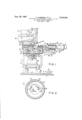
- FIG. 1 is a partly sectional side view of the machine in schematic representation
- FIG. 2 is a cross section taken along the line 22 in FIG. 1.
- a horizontally displaceable slider 2 which is joined with a rack 3 meshing with pinion 4 on the shaft 5 of a motor 6 operable in one or the other direction for shifting the slider 2 to one or the other side.
- the slider 2 carries four legs 8 of a frame structure 7, only two legs being visible on the drawing.
- Each leg is formed by a hydraulic cylinder 9 with a piston rod 10 which is vertically displaceable in the cylinder.
- the pistons By supplying or draining oil from each cylinder, the pistons can be moved upwardly or downwardly for changing the height of the frame structure 7.
- the flange 14 carries a coaxial drum generally denoted by 20.
- the drum has a bottom wall 21, a top wall 22 and a circularly cylindrical jacket 23.
- the bottom Wall 21 is firmly joined with the flange 14.
- the top wall 22 has a central circular opening 24.
- Top, bottom and peripheral jacket of drum 20 consist of sheet steel and are internally lined with refractory material 24 which covers the entire inner wall surface and has an opening 26 registering with the opening 24.
- the ladlesuspension means comprise a support 28 on which a slider 29 is horizontally displaceable.
- the ladle 27 has a shape -as conventional in steel mills and consists of an outer steel shell and an inner refractory lining 31.
- the bottom of the ladle has an opening 32 which can be closed by a conventional plug 33.
- a bracket 34 on each side of the ladle is mounted on the slider 29 and carries in its upper end a pivot for the ladle.
- the ladle 27, thus supported on the slider 29, can be moved into and out of the illustrated position by correspondingly shifting the slider.
- an outlet pipe 36 Attached to a bottom plate 35 of the ladle 27 and in alignment with the bottom opening 32 is an outlet pipe 36.
- This pipe can be cooled with water and for this purpose has a double wall indicated at 37.
- Two nipples or stub pipes 38 and 39 serve for passing the water through the jacket space of pipe 36.
- the pipe 36 extends vertically downward. At some distance below the ladle, the pipe 36 is bent laterally so as to form a horizontal portion 40 (FIG. 2). The lower end of the pipe is curved about 90 away from portion 40 in the same horizontal plane and forms another, likewise horizontal portion 41 of very short length (FIG. 2).
- a foundation structure 42 with guide means 43 for a slider 44 which can be horizontally displaced on foundation 42 in two coordinate directions, namely in the plane of illustration and per pendicularly thereto.
- the slider 44 carries a chamber structure denoted as a whole by 45.
- the design or shape of the chamber structure 45 generally resembles that of the casting molds'or ingot molds heretofore employed in continuous stock-casting processes, except that the longitudinal axis of the chamber 45 extends horizontally.
- the cross-sectional shape of the chamber 45 corresponds to that of the elongated rod or other product to be cast. Consequently, the, space formed by the chamber may be prismatic or cylindrical.
- the chamber space has the shape of a circular cylinder.
- the wall of chamber 45 is cooled with water and forms a jacket space 46 which communicates with inlet and outlet ducts 47 and 48 for the supply and discharge of the coolant water.
- the left side of the chamber 45 is closed by a rear wall 49.
- the right or front end 50 is continuously open.
- the rear wall 49 has an opening 51 connected with a material supply pipe 52.
- This pipe is also water cooled and for this purpose has a double wall indicaed at 53, as well as nipples 54 and 55 for the supply and discharge of coolant water.
- the shape of pipe 52 is similar to that of
- the top portion 11 of the frame structure 7 carries a bearing 12 for a vertical shaft 13 which is provided above the frame portion 11 with a flange 14 and below the pipe 36, that is, the horizontal portion of pipe 52 adjacent to the chamber 45, is followed by a vertical portion 57 extending downwardly through the openings 24 and 26 into the drum 20.
- the vertical portion 57 is continued by a horizontal portion 58 (FIGS. 1, 2) whose end curves laterally away to form still another horizontal but short portion 59 in the same horizontal plane (FIG. 2).
- the tube 52 is located in the interior of the drum 20 in the particular manner apparent from FIGS. 1 and 2.
- the opening 60 of tube 52 is located in eccentric relation to the axis of drum 20 and below the top wall 22.
- the direction of the opening 60 is tangential to a circular cylinder whose axis coincides with the axis of the drum 20.
- the radial distance of opening 60 from the axis of drum 20 can be changed by displacing the slider 44.
- a ladle 27 according to FIG. 1 is filled with molten steel 61 and is placed upon the slider 29 with the aid of a crane.
- the tube 36 then passes through the opening 24 into the interior of the drum 20.
- the ladle 27 is then slightly moved toward the left by correspondingly shifting the supporting slider 29, so that the opening 62 of pipe 36 is situated beneath the top wall 22 of drum 20.
- the opening 62 then extends tangentially to a circular cylinder whose axis coincides with the axis of the drum 20, in this respect corresponding to the positioning of the opening 60 of tube 62.
- the adjustment now is the one shown in FIG. 2.
- the drum 20 is placed in rotation by means of the motor 18 in the direction of the arrow b shown in FIG. 2. This direction is opposed to that of the tube openings 60 and 62.
- the pipes 36 and 52 as well as the casting chamber 45 are supplied with coolant water. Thereafter the plug 43 is pulled out of the ladle outlet opening so that the melt 61 drains through the opening 32 and the pipe 36 into the rotating drum 20.
- the melt issuing from opening 62 flows onto the bottom of drum 20 and is then flung outward by centrifugal force toward the drum periphery. Consequently there is formed a ring-shaped body 63 consisting of liquid steel and having a radial thickness which increases with the further supply of molten steel from the ladle 27.
- the opening 60 of tube 52 passes into the ringshaped body 63. Since this opening is opposed to the direction of rotation b, some of the molten steel enters into the pipe 52 and is pressed through this pipe into the chamber 45.
- the opening 62 of the tube 36 also becomes immersed in the rotating melt.
- the acceleration due to centrifugal force in the rotating drum 20 is considerably larger than the acceleration due to gravity. This has the effect that any impurities contained in the melt 61 and having a lower specific gravity than the molten metal, are floated to the surface with a particularly good effectiveness. Hence such impurities are rapidly transported to those localities of the ring-shaped body 63 that have the smallest distance from the drum axis.
- the molten material entering into the opening 60 thus exhibits a considerably higher degree of purity than the melt entering into the casting mold of the conventional continuous casting devices.
- the melt enters into the vertically upright casting mold only by gravity.
- the melt entering into the chamber 45 is subjected to the high pressure produced by centrifugal force.
- This pressure can be made as high as desired, simply by correspondingly selecting the rotating speed of the motor 18.
- the resulting product 66 possesses a structure which is considerably denser and therefore better than the structure obtainable with the continuous stockcasting method heretofore known.
- the known casting processes rely on gravity for filling the molds so that these must be arranged vertically. Consequently, the resulting elongated product issues in a vertical direction which requires cutting it into relatively short pieces or guiding it by relatively complicated direction-changing means so that it will travel on a generally horizontal path.
- the latter expedient is applicable only with relatively thin stock material.
- the invention affords the possibility of operating with a horizontal casting chamber 45 from which the strand product 46 issues already in a horizontal direction. The product, therefore, need not necessarily be cut into shorter pieces but, in principle, can be given any desired or infinite length. This oflers the possibility, for example, to guide the resulting strand product without interruption directly into a rolling mill.
- Apparatus for producing intermediate products in elongated rod or strand shape comprising:
- (g) means for cooling said casting chamber and means for guiding the solidified casting issuing from the open end of said casting chamber.
- said casting chamber having a horizontal axis so that the casting issues in a horizontal direction.
- Continuous casting apparatus comprising means for changing the radial distance be- References Cited UNITED STATES PATENTS DeRomilly 103-401 X Gurley 103101 Kuhn 74-45 Mattson 2257.2 X Armand et a1. 22-57.2
Landscapes
- Engineering & Computer Science (AREA)
- Mechanical Engineering (AREA)
- Continuous Casting (AREA)
- Casting Support Devices, Ladles, And Melt Control Thereby (AREA)
Applications Claiming Priority (1)
| Application Number | Priority Date | Filing Date | Title |
|---|---|---|---|
| DED41505A DE1208044B (de) | 1963-05-08 | 1963-05-08 | Vorrichtung zum kontinuierlichen Giessen von Metall |
Publications (1)
| Publication Number | Publication Date |
|---|---|
| US3338298A true US3338298A (en) | 1967-08-29 |
Family
ID=7046151
Family Applications (1)
| Application Number | Title | Priority Date | Filing Date |
|---|---|---|---|
| US365309A Expired - Lifetime US3338298A (en) | 1963-05-08 | 1964-05-06 | Apparatus for continuous casting of rod and other strand material |
Country Status (7)
| Country | Link |
|---|---|
| US (1) | US3338298A (fr) |
| AT (1) | AT241713B (fr) |
| BE (1) | BE647450A (fr) |
| DE (1) | DE1208044B (fr) |
| FR (1) | FR1391640A (fr) |
| GB (1) | GB1043877A (fr) |
| LU (1) | LU45918A1 (fr) |
Cited By (1)
| Publication number | Priority date | Publication date | Assignee | Title |
|---|---|---|---|---|
| US3467168A (en) * | 1966-04-25 | 1969-09-16 | Oglebay Norton Co | Continuous casting apparatus and method including mold lubrication,heat transfer,and vibration |
Citations (5)
| Publication number | Priority date | Publication date | Assignee | Title |
|---|---|---|---|---|
| US261436A (en) * | 1882-07-18 | Heney felix louis woems de eomilly | ||
| US1722289A (en) * | 1928-09-10 | 1929-07-30 | John W Gurley | Pump |
| US2471876A (en) * | 1936-10-17 | 1949-05-31 | Gen Motors Corp | Clothes-washing and cleaning machine |
| US2702419A (en) * | 1951-11-29 | 1955-02-22 | Ethyl Corp | Process of casting alkali metals |
| US2996771A (en) * | 1956-01-10 | 1961-08-22 | Electro Chimie Soc D | Method and appartus for horizontal pouring of metals |
Family Cites Families (1)
| Publication number | Priority date | Publication date | Assignee | Title |
|---|---|---|---|---|
| DE525225C (de) * | 1930-05-10 | 1931-05-22 | Georg Pemetzrieder | Gussverfahren unter Verwendung eines in einem festen Gehaeuse umlaufenden Schleudertellers |
-
1963
- 1963-05-08 DE DED41505A patent/DE1208044B/de active Pending
-
1964
- 1964-04-21 LU LU45918D patent/LU45918A1/xx unknown
- 1964-05-04 BE BE647450D patent/BE647450A/xx unknown
- 1964-05-06 GB GB18874/64A patent/GB1043877A/en not_active Expired
- 1964-05-06 US US365309A patent/US3338298A/en not_active Expired - Lifetime
- 1964-05-06 FR FR973551A patent/FR1391640A/fr not_active Expired
- 1964-05-08 AT AT402664A patent/AT241713B/de active
Patent Citations (5)
| Publication number | Priority date | Publication date | Assignee | Title |
|---|---|---|---|---|
| US261436A (en) * | 1882-07-18 | Heney felix louis woems de eomilly | ||
| US1722289A (en) * | 1928-09-10 | 1929-07-30 | John W Gurley | Pump |
| US2471876A (en) * | 1936-10-17 | 1949-05-31 | Gen Motors Corp | Clothes-washing and cleaning machine |
| US2702419A (en) * | 1951-11-29 | 1955-02-22 | Ethyl Corp | Process of casting alkali metals |
| US2996771A (en) * | 1956-01-10 | 1961-08-22 | Electro Chimie Soc D | Method and appartus for horizontal pouring of metals |
Cited By (1)
| Publication number | Priority date | Publication date | Assignee | Title |
|---|---|---|---|---|
| US3467168A (en) * | 1966-04-25 | 1969-09-16 | Oglebay Norton Co | Continuous casting apparatus and method including mold lubrication,heat transfer,and vibration |
Also Published As
| Publication number | Publication date |
|---|---|
| LU45918A1 (fr) | 1964-06-22 |
| AT241713B (de) | 1965-08-10 |
| DE1208044B (de) | 1965-12-30 |
| BE647450A (fr) | 1964-08-31 |
| FR1391640A (fr) | 1965-03-05 |
| GB1043877A (en) | 1966-09-28 |
Similar Documents
| Publication | Publication Date | Title |
|---|---|---|
| US3646988A (en) | Induction apparatus for continuous and semicontinuous casting | |
| US3467166A (en) | Method of continuous and semicontinuous casting of metals and a plant for same | |
| US4465118A (en) | Process and apparatus having improved efficiency for producing a semi-solid slurry | |
| US2752648A (en) | Apparatus for the production of tubular metallic objects | |
| US3409068A (en) | Method of continuously casting tubes using a rotating mandrel | |
| US4430388A (en) | Method and apparatus for continuously casting a hollow metal blank, and the resulting blank | |
| US4137961A (en) | Continuous casting of metals | |
| US3338298A (en) | Apparatus for continuous casting of rod and other strand material | |
| SU1435144A3 (ru) | Устройство дл вертикального непрерывного лить трубных заготовок из чугуна с шаровидным графитом | |
| US3702630A (en) | Apparatus for casting solid cylindrical metallic objects | |
| US2571033A (en) | Apparatus for pouring molten metal | |
| US3340924A (en) | Apparatus for continuous casting of hollow billets | |
| NO770606L (no) | Fremgangsm}te og anordning for kontinuerlig st¦pning av metallsmelte i st¦peformer. | |
| CN201304475Y (zh) | 在直形连铸机上生产直径≥φ800mm圆坯的连铸设备 | |
| US3450188A (en) | Continuous casting method and arrangement | |
| US4243092A (en) | Continuous casting | |
| US3583469A (en) | Method of continuously casting solid state cylinders | |
| SU1087056A3 (ru) | Способ непрерывного изготовлени металлических полых заготовок и устройство дл его осуществлени | |
| US3304585A (en) | Graphite continuous casting mold | |
| US4375830A (en) | Method and apparatus for supporting a steel strand produced during a continuous strand casting method | |
| US3693701A (en) | Continuous casting plant for continuously casting hot liquid metals | |
| US3672431A (en) | Apparatus and procedures for continuous casting of metal ingots | |
| US3625276A (en) | Centrifugal casting of tubes including slag separation | |
| US3623533A (en) | Method of molten metal height control in curved mold continuous casting | |
| US2303139A (en) | Method of and apparatus for centrifugally degasifying molten metal |