US3338336A - Suspension of lifts - Google Patents
Suspension of lifts Download PDFInfo
- Publication number
- US3338336A US3338336A US505616A US50561665A US3338336A US 3338336 A US3338336 A US 3338336A US 505616 A US505616 A US 505616A US 50561665 A US50561665 A US 50561665A US 3338336 A US3338336 A US 3338336A
- Authority
- US
- United States
- Prior art keywords
- car
- platform
- pair
- guide
- load
- Prior art date
- Legal status (The legal status is an assumption and is not a legal conclusion. Google has not performed a legal analysis and makes no representation as to the accuracy of the status listed.)
- Expired - Lifetime
Links
Images
Classifications
-
- B—PERFORMING OPERATIONS; TRANSPORTING
- B66—HOISTING; LIFTING; HAULING
- B66B—ELEVATORS; ESCALATORS OR MOVING WALKWAYS
- B66B19/00—Mining-hoist operation
- B66B19/002—Mining-hoist operation installing or exchanging guide rails
-
- B—PERFORMING OPERATIONS; TRANSPORTING
- B66—HOISTING; LIFTING; HAULING
- B66B—ELEVATORS; ESCALATORS OR MOVING WALKWAYS
- B66B11/00—Main component parts of lifts in, or associated with, buildings or other structures
- B66B11/02—Cages, i.e. cars
- B66B11/026—Attenuation system for shocks, vibrations, imbalance, e.g. passengers on the same side
- B66B11/0266—Passive systems
-
- B—PERFORMING OPERATIONS; TRANSPORTING
- B66—HOISTING; LIFTING; HAULING
- B66B—ELEVATORS; ESCALATORS OR MOVING WALKWAYS
- B66B7/00—Other common features of elevators
- B66B7/02—Guideways; Guides
Definitions
- This invention relates to a passenger and goods lift, in which the point of suspension of the car lies off centre.
- the car of a lift has a fixed centre of gravity; and the load, which changes its position within the car, also has its own centre of gravity. What is of concern in the present invention is the position of the centre of gravity in the horizontal plane of projection.
- the centre of gravity of the lift car is a fixed point. In the most troublesome case, the maximum permissible load in the lift may wander round with its centre of grav ity at the edge of the car floor.
- a slab of lead, for example, may be standing right against the car wall, in which case the centre of gravity of the load lies at the edge of the car floor. In the course of loading or load changing, therefore, the centre of gravity of the carried load may be situated at any point on the floor of the car.
- This combined centre of gravity may migrate within a certain area, determined by the movement of the carried load.
- the perimeter of this area of possible migration of the combined centre of gravity is defined as the maximum carried load moves round the side edges of the car floor.
- the area of possible migration of the combined centre of gravity contains only one combined centre of gravity where the loaded lift car produces no turning moment. That is to say, no turning moment is produced when the combined centre 'of gravity lies directly above or below the point of suspension of the car. All other points in this area, which may lie round about the point of suspension, produce moments in various directions, according to the position to which the carried load has moved. For this reason, any lift car, whenever the load moves within it, will tilt to the extent allowed by the play between it and the guides. This tilting or jolting of the car induces a feeling of insecurity in the passengers, especially in passenger lifts.
- the area of possible migration of the combined centre of gravity may be round or rectangular, according to the shape of the lift floor.
- the inventor proposes that the point of suspension of the lift car be arranged to lie within geometrical figures such that no change arises in the direc tion of the turning moment, however the carried load may move, namely in or near a corner quadrant and outside the area of possible migration of the combined centre of gravity of the car.
- the car with its gravity moment can be guided by one rail or round guide fitted in any desired position in the lift shaft, even within the same quadrant as the point of suspension.
- any form of power can be used to drive the lift.
- the car can be driven by pulley transmission or hydraulically.
- the single-guide system is not only better technically, but is far cheaper.
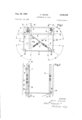
- FIGURE 1 is a diagrammatic plan, partly in section, of a lift installation conforming to the invention, showing how the point of suspension is determined, and of the lift guide system;
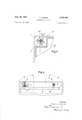
- FIGURE 2 is a diagrammatic section along the line A-B in FIGURE 1;
- FIGURES 3 and 4 are diagrammatic plans of other possible types of guide systems, showing only the guide arrangement and part of the car.
- a guide 2 along which the car 3 of the lift rnoves up and down, .driven for example by ropes (not shown) which passes over a driving pulley (not shown) is fitted in a normal lift shaft, 1.
- the chassis of the car 3 consists of a fioor frame 6, which is provided with longitudinal and transverse beams; to the frame 6 are attached anchorage members, 7 and 8 which extend the same way as the lift shaft. Solid-wall or lattice reinforcements may be provided between these anchorages members. From the lower end of the anchorage member 7, which extends below the car flow to provide for trussing, diagonal cross-braces 9 run to the ends of the car floor. These cross-braces may incorporate adjusters.
- tension members 10 brace the roof of the lift car in relation to vertical chassis anchorages 7 and 8.
- the side walls of the car between the car floor and the car roof are held together by struts 10.
- Arrows 11, 12 and 13 indicate the possibilities for entrance gates on three sides.
- Rollers 14 and 15 are provided on the anchorage member 7, with the aid of which rollers the lift car moves along guide 2.
- the point of attachment M for the car suspension (in the form of a rope, for example) may also be located upon the anchorage 7.
- rollers 14 and 15 absorb the turning moment produced by the total Weight of the car through four force-transmission components, the car guide being located, in the example shown in FIGURE 1, in the corner quadrant R.
- the lift car numbered 3 in FIGURE 1 may be regarded for the purposes of the following explanation, as identical with the plan of the ear fioor.
- the centre of gravity of the car alone be assumed to lie at S in the car fioor.
- the position of this centre of gravity is unchangeable, being determined by the construction of the car.
- the combined centre of gravity S of the car, and its load is, on the other hand, the resultant of the centre of gravity of the car itself and that of the load within the car. Since the load may change its position within the car, the combined centre of gravity is subject to migration. For instance, a heavy object may be standing right against the car wall, in which case the combined centre of gravity will lie close to the wall. However, continual migration of the combined centre of gravity may take place, caused by changes in position of the carried load on the car fioor. In the present instance, let this combined centre of gravity be assumed to lie within the area F which is bounded by the chain lines W, X, Y and Z (FIG- URE 1).
- the combined centre of gravity S may (for example) lie in that portion of Y which falls between X and W, or at the point of intersection of X and Y (the position in which it is shown in FIGURE 1).
- the lines W, X, Y and Z may thus be produced to define the corner quadrants R, R, R" and R.
- the car suspension point M is located in or near R, one of these corner quadrants.
- the corner quadrant containing the point of suspension can he arrived at similarly for a lift having a car floor of any desired shape, such as circular or polygonal.
- This location of the point of suspension in conjunction with the -use of a single guide, enables the main members to be disposed on one wall of the lift shaft in a particularly compact manner, occupying very little space, so that three sides remain available for entrance gates.
- the single-guide system also makes it possible for the lift car to be guided to rotate in a helix, so that the installation can be used, for example, as a hoist for supplying machinery staggered at different levels.
- FIGURE 2 which is a cross-section along the line A-B in FIGURE 1, it can be seen that rollers 14 and 15, as one guide unit, are fitted as far as possible away from the lower guide units 14/15' on anchorage member 7.
- Roller 15' which is near the lower end of anchorage member 7, lies on the opposite side of this with respect to upper roller 14.
- Roller 14 is similarly arranged with respect to upper roller 15, so that the turning moment about the X axis is taken up by rollers 14 and 15', and the turning moment about the Y axis is taken up by rollers 15 and 14'.
- a second rail, 17, of light construction acts mererly as a guard against swinging round.
- Roller 16, conneted by anchorage 8 to the lift car, runs on guide 17.
- Anchorage 8, similarly to the anchorage 7, may extend for the height of the lift car, but guide roller 16 should preferably be attached only to an arm 18, which can be attached at any desired height to anchorage 8.
- FIGURE 2 arm 18, with guide roller 16, is fitted level with the floor of car 3.
- Suitable attachments 19 and 19' are provided on anchorage member 7, for mounting rollers 14 and 14.
- the lift car can nautrally still be provided with an emergency brake, shown diagrammatically at 20.
- rack guides are provided, as is standard practice, these being brought into use only if the normal guides should be destroyed.
- one roundsectioned guide 2 is used instead of the two H-sectioned guides 2 shown in FIGURES 1 and 2.
- the turning moment in each direction is taken by one roller at the top 14" and one roller below 15".
- This construction is the simplest conceivable and well suited to small loads.
- FIGURES 1 and 2 consisting of roller 16 and a second guide 17
- the same function can be discharged by, for example, a ram 21 (FIGURE 4), articulated by arm 22, to floor frame 6.
- Ram 21 in that case, both supports the car and prevents it from swinging round.
- the guide and suspension point of the lift car can be located at will.
- both the guide and the point of suspension lie in one and the same corner quadrant R.
- the car guide is situated within corner quadrant R, whereas suspension point 'M lies within corner quadrant R.
- Corner quadrant R is the geometrical locus for all points of suspension of the car for which, notwithstanding changes in the position of the load carried in the car, there is no change of direction in the turning moment.
- corner quadrant in this connection, is used to mean not only a geometrical figure bounded by straight lines, but also one having a curved periphery (a circle, for example) but outside the area F
- rollers referred to in this specification for example, the rollers 14, 15, 14', 15', 14 and 15
- shoes of the well-known form may be replaced by shoes of the well-known form.
- a lift installation for carrying a load upwards and downwards which comprises, in combination,
- first and second pairs of guide surfaces a single fixed vertical rail defining first and second pairs of guide surfaces, the planes of said first pair of guide surfaces being parallel and substantially perpendicular to the planes of said second pair of guide surfaces,
- a substantially rectangular load-bearing platform means for supporting said platform against free ver tical movement at at least one point, said point being located adjacent one corner of said rectangular platform,
- said first pair of roller surfaces being positioned to engage with said first pair of guide surfaces to prevent rotation of said paltform about a first roll axis which is parallel to the planes of said first pair of guide surfaces and which passes through said rail,
- said second pair of roller surfaces being positioned to engage with said second pair of guide surfaces to prevent rotation of said platform about a second roll axis which is parallel to the planes of said second pair of guide surfaces and which passes through said rail,
- said vertical rail being positioned adjacent said one corner of said rectangular platform such that the combined center of gravity of said platform and said load lies on the same side of each of said roil axis regardless of where said load is placed on said platform.
- a lift installation as set forth in claim 1 including means for preventing pivotal motion of said platform in a horizontal plane about said rail.
- a lift installation as set forth in claim 1 including a vertical support member afiixed to said corner of said platform adjacent said rail with said vertically spaced roller surfaces being attached to said vertical support member and said means for supporting said platform being attached to said vertical support member.
Landscapes
- Physics & Mathematics (AREA)
- Fluid Mechanics (AREA)
- Engineering & Computer Science (AREA)
- Civil Engineering (AREA)
- Mechanical Engineering (AREA)
- Structural Engineering (AREA)
- Lift-Guide Devices, And Elevator Ropes And Cables (AREA)
- Forklifts And Lifting Vehicles (AREA)
Applications Claiming Priority (1)
| Application Number | Priority Date | Filing Date | Title |
|---|---|---|---|
| DEL0049173 | 1964-11-02 |
Publications (1)
| Publication Number | Publication Date |
|---|---|
| US3338336A true US3338336A (en) | 1967-08-29 |
Family
ID=7272826
Family Applications (1)
| Application Number | Title | Priority Date | Filing Date |
|---|---|---|---|
| US505616A Expired - Lifetime US3338336A (en) | 1964-11-02 | 1965-10-29 | Suspension of lifts |
Country Status (7)
| Country | Link |
|---|---|
| US (1) | US3338336A (de) |
| AT (1) | AT287239B (de) |
| BE (1) | BE671797A (de) |
| CH (1) | CH441665A (de) |
| DE (1) | DE1431059A1 (de) |
| GB (1) | GB1121755A (de) |
| NL (1) | NL152817B (de) |
Cited By (3)
| Publication number | Priority date | Publication date | Assignee | Title |
|---|---|---|---|---|
| FR2318339A1 (fr) * | 1975-07-15 | 1977-02-11 | Euratom | Guidage isocinetique sur deux colonnes |
| US5193651A (en) * | 1990-09-10 | 1993-03-16 | Hitachi, Ltd. | Elevator apparatus |
| WO2017016780A1 (de) * | 2015-07-24 | 2017-02-02 | Inventio Ag | Automatisierte montagevorrichtung zur durchführung von installationen in einem aufzugschacht einer aufzuganlage |
Families Citing this family (3)
| Publication number | Priority date | Publication date | Assignee | Title |
|---|---|---|---|---|
| CH620657A5 (en) * | 1977-08-16 | 1980-12-15 | Swisel Beleuchtungssysteme Ag | Apparatus for hoisting fixtures |
| JPS60223772A (ja) * | 1984-04-18 | 1985-11-08 | 三菱電機株式会社 | エレベ−タ用ガイドレ−ル |
| CN110395644B (zh) * | 2018-04-25 | 2020-12-01 | 三菱电机株式会社 | 电梯轿厢和电梯装置 |
Citations (4)
| Publication number | Priority date | Publication date | Assignee | Title |
|---|---|---|---|---|
| US937256A (en) * | 1908-12-08 | 1909-10-19 | Mary C Minnich | Portable telescoping elevator. |
| US1986620A (en) * | 1934-06-21 | 1935-01-01 | Atlantic Elevator Company | Elevator |
| GB956332A (en) * | 1962-07-10 | 1964-04-22 | Damjan Hladnik | Improvements in vertically moving cable lifts |
| US3239031A (en) * | 1963-01-07 | 1966-03-08 | Lodige Alois | Under-floor elevator |
-
1964
- 1964-11-02 DE DE19641431059 patent/DE1431059A1/de active Pending
-
1965
- 1965-10-15 AT AT934465A patent/AT287239B/de not_active IP Right Cessation
- 1965-10-22 CH CH1462665A patent/CH441665A/de unknown
- 1965-10-28 NL NL656513967A patent/NL152817B/xx unknown
- 1965-10-29 US US505616A patent/US3338336A/en not_active Expired - Lifetime
- 1965-11-01 GB GB46092/65A patent/GB1121755A/en not_active Expired
- 1965-11-03 BE BE671797D patent/BE671797A/xx unknown
Patent Citations (4)
| Publication number | Priority date | Publication date | Assignee | Title |
|---|---|---|---|---|
| US937256A (en) * | 1908-12-08 | 1909-10-19 | Mary C Minnich | Portable telescoping elevator. |
| US1986620A (en) * | 1934-06-21 | 1935-01-01 | Atlantic Elevator Company | Elevator |
| GB956332A (en) * | 1962-07-10 | 1964-04-22 | Damjan Hladnik | Improvements in vertically moving cable lifts |
| US3239031A (en) * | 1963-01-07 | 1966-03-08 | Lodige Alois | Under-floor elevator |
Cited By (9)
| Publication number | Priority date | Publication date | Assignee | Title |
|---|---|---|---|---|
| FR2318339A1 (fr) * | 1975-07-15 | 1977-02-11 | Euratom | Guidage isocinetique sur deux colonnes |
| US5193651A (en) * | 1990-09-10 | 1993-03-16 | Hitachi, Ltd. | Elevator apparatus |
| WO2017016780A1 (de) * | 2015-07-24 | 2017-02-02 | Inventio Ag | Automatisierte montagevorrichtung zur durchführung von installationen in einem aufzugschacht einer aufzuganlage |
| CN107922166A (zh) * | 2015-07-24 | 2018-04-17 | 因温特奥股份公司 | 用于在电梯设备的电梯竖井中执行安装的自动化的装配设备 |
| AU2016299141B2 (en) * | 2015-07-24 | 2019-08-08 | Inventio Ag | Automated mounting device for performing assembly jobs in an elevator shaft of an elevator system |
| CN107922166B (zh) * | 2015-07-24 | 2020-01-10 | 因温特奥股份公司 | 用于在电梯设备的电梯竖井中执行安装的自动化的装配设备 |
| US10836610B2 (en) | 2015-07-24 | 2020-11-17 | Inventio Ag | Automated mounting device for performing assembly jobs in an elevator shaft of an elevator system |
| US10843902B2 (en) | 2015-07-24 | 2020-11-24 | Inventio Ag | Automated mounting device for performing assembly jobs in an elevator shaft of an elevator system |
| US10850946B2 (en) | 2015-07-24 | 2020-12-01 | Inventio Ag | Automated mounting device for performing assembly jobs in an elevator shaft of an elevator system |
Also Published As
| Publication number | Publication date |
|---|---|
| CH441665A (de) | 1967-08-15 |
| NL6513967A (de) | 1966-05-03 |
| GB1121755A (en) | 1968-07-31 |
| DE1431059A1 (de) | 1968-10-17 |
| BE671797A (de) | 1966-03-01 |
| AT287239B (de) | 1971-01-11 |
| NL152817B (nl) | 1977-04-15 |
Similar Documents
| Publication | Publication Date | Title |
|---|---|---|
| US10836608B2 (en) | Elevator arrangement and method | |
| KR100297123B1 (ko) | 엘리베이터 | |
| US9845227B2 (en) | Mobile crane | |
| CN116249668B (zh) | 升降机设备 | |
| US10961085B2 (en) | Low-construction trolley for wire rope hoist | |
| US7261184B2 (en) | Elevator system and triangulated support structure for the same | |
| HK1049476A1 (en) | Cable elevator | |
| JPH11246145A5 (de) | ||
| US3338336A (en) | Suspension of lifts | |
| JP4270642B2 (ja) | エレベーター装置 | |
| JPH11139730A (ja) | エレベーター | |
| JP6477255B2 (ja) | 機械室レスエレベータ | |
| JP4376585B2 (ja) | 機械室レスエレベータ装置 | |
| JP4091326B2 (ja) | エレベーター装置 | |
| CN209890037U (zh) | 一种桥式钢带型土建结构 | |
| US3344932A (en) | Crab runway for an overhead travelling crane | |
| KR102933393B1 (ko) | 엘리베이터 케이지의 편심 방지시스템 | |
| KR102919289B1 (ko) | 엘리베이터 케이지의 편심 방지시스템 | |
| CN110294392B (zh) | 轿厢门机的安装结构、安装方法及主连接支架、辅连接支架 | |
| JPWO2005077806A1 (ja) | エレベータ装置 | |
| JPWO2007020674A1 (ja) | エレベータ装置 | |
| CN115151503A (zh) | 电梯系统 | |
| JP2000095455A (ja) | エレベ―タ―の安全装置 | |
| SU1250515A1 (ru) | Подъемник | |
| RU87154U1 (ru) | Подъемник с уравнительной канатной системой |