US3338352A - Self-adjusting brake cylinder for automotive vehicle - Google Patents
Self-adjusting brake cylinder for automotive vehicle Download PDFInfo
- Publication number
- US3338352A US3338352A US462920A US46292065A US3338352A US 3338352 A US3338352 A US 3338352A US 462920 A US462920 A US 462920A US 46292065 A US46292065 A US 46292065A US 3338352 A US3338352 A US 3338352A
- Authority
- US
- United States
- Prior art keywords
- rod
- brake
- piston
- rings
- ring
- Prior art date
- Legal status (The legal status is an assumption and is not a legal conclusion. Google has not performed a legal analysis and makes no representation as to the accuracy of the status listed.)
- Expired - Lifetime
Links
Images
Classifications
-
- F—MECHANICAL ENGINEERING; LIGHTING; HEATING; WEAPONS; BLASTING
- F16—ENGINEERING ELEMENTS AND UNITS; GENERAL MEASURES FOR PRODUCING AND MAINTAINING EFFECTIVE FUNCTIONING OF MACHINES OR INSTALLATIONS; THERMAL INSULATION IN GENERAL
- F16D—COUPLINGS FOR TRANSMITTING ROTATION; CLUTCHES; BRAKES
- F16D65/00—Parts or details
- F16D65/38—Slack adjusters
- F16D65/40—Slack adjusters mechanical
- F16D65/52—Slack adjusters mechanical self-acting in one direction for adjusting excessive play
- F16D65/54—Slack adjusters mechanical self-acting in one direction for adjusting excessive play by means of direct linear adjustment
- F16D65/546—Slack adjusters mechanical self-acting in one direction for adjusting excessive play by means of direct linear adjustment for mounting within the confines of a drum brake
-
- B—PERFORMING OPERATIONS; TRANSPORTING
- B61—RAILWAYS
- B61H—BRAKES OR OTHER RETARDING DEVICES SPECIALLY ADAPTED FOR RAIL VEHICLES; ARRANGEMENT OR DISPOSITION THEREOF IN RAIL VEHICLES
- B61H15/00—Wear-compensating mechanisms, e.g. slack adjusters
- B61H15/0007—Wear-compensating mechanisms, e.g. slack adjusters mechanical and self-acting in one direction
- B61H15/0014—Wear-compensating mechanisms, e.g. slack adjusters mechanical and self-acting in one direction by means of linear adjustment
- B61H15/0021—Wear-compensating mechanisms, e.g. slack adjusters mechanical and self-acting in one direction by means of linear adjustment with cams, by friction or clamping
Definitions
- ABSTRACT OF THE DISCLOSURE A self-adjusting brake cylinder in which at least one piston moves along a rod and carries with it at least one rod gripping ring.
- a brake cylinder comprising an automatic play take-up device incorporated in the cylinder comprising at least one piston slidably movable in said cylinder with a return play limited by said device
- the invention is characterized primarily in that said piston is movable in relation to an inner rod mounted in said cylinder and having tightly fitted thereon a split spring ring disposed between two abutment faces formed on said piston with a play equal to said play, the friction set up between said ring and said rod being such that the ring may easily be carried along by the piston along said rod during a brake application, said ring resisting however the return effort exerted on the piston during the brake release movement by the elastic return means acting upon said brake.
- FIGURE 1 is a diagrammatic and fragmentary axial section showing the brake cylinder of this invention.
- FIGURE 2 is a plane view of one of the spring rings of the play take-up device incorporated in this cylinder.
- the brake cylinder illustrated comprises a cylinder body 1 of a type conventional notably in drum brakes; this cylinder body is provided intermediate its ends with a port 2 for delivering fluid under pressure to the cylinder and with another port 3 receiving a drain plug.
- Each piston 4 is insealed and sliding engagement with the cylinder wall by means of a packing 6, and is connected to the adjacent end of cylinder 1 by means of a protection cup 7, and the central portion 8 of its outer face constitutes a thrust face engageable by a brake shoe of conventional type (not shown).
- the play take-up device incorporated in the brake cylinder comprises a rod 10 fitting freely in a corresponding cavity of piston 4, this rod being either rigid with the opposite piston or mounted therein in the same manner as in piston 4 illustrated in the figure, together, in this case, with all the component elements of the play take-up device which are disclosed hereinafter.
- These rings 12 may be of any suitable commercially available type and conventionally used as retaining or assembly members, such as the circlip rings known under the trademark Truarc and the trade name Grip-Ring.
- These rings 12 co-act in the axial direction at one end with a shoulder stop 13 forming the bottom of said cavity 11 and at the opposite end a washer 14 associated with these rings 12 is adapted to engage an abutment ring 15 resiliently fitted in a internal groove formed in said cavity 11.
- the free mounting of the rod 10 in piston 4 is such that any undesired trapping of control fluid between the end of this rod and the bottom of said cavity is definitely precluded.
- the axial play E of said rings 12 and washer 14 between the shoulder stop 13 and the abutment ring 15 corresponds to the permissible return play of piston 4 when the brake is released.
- This return movement is produced by the elastic return means associated with the brake (not shown) and the frictional effort due to the engagement between the rings 12 and rod 10 is calculated to be somewhat higher than this return effort; in other words, the rings 12 act as a piston stop during a brake release, whereby the inoperative position of the brake control means is that shown in FIGURE 1.
- this frictional effort obtained between said rings 12 and said rod 10 is definitely inferior to the effort likely to be applied 'by the fluid under pressure to the piston 4, and if for any reason the piston stroke'E were not sufficient during a brake application, for example as a consequence of the gradual wearing of the brake linings, the piston 4 will easily carry along, through the medium of the abutment ring 15 and washer 14, the set of spring rings 12 which, in this case, will slide axially along the rod 10.
- the number of spring rings 12 depends on the nature of the ring or rings used in the brake cylinder and on the effort contemplated for returning the brake concerned to its release position, the ring or rings being in all cases such that the frictional engagement between these rings and the rod will generate the same mechanical frictional resistance in either direction.
- a groove 9 will be formed in the outer end of this rod for engagement by the ring or the outermost ring if several rings 12 are provided.
- the inner face of this groove 9 which is opposite to the ring will extend substantialy at right angles to the axis of rod 10, and the other inner face of the groove 9 will be substantially frustoconical or tapered, as shown; thus, the stopping action of this groove will be unidirectional, the ring having the possibility of escaping from this groove by slipping on said tapered side face.
- this groove 9 is formed in both ends of the rod 10.
- the extreme movement of one or the other of these rings or sets of rings 12 along the rod 10 cannot take place except if for any reason an asymmetric condition developed in the operation of the device.
- the groove 9 will protect the device against possible damages.
- a brake cylinder with built-in, self-adjustment means comprising at least one piston slidably and sealingly fitted in said cylinder with the return play thereof being limited by said adjustment means, a bore in said piston, two stops provided in said bore with a spacing equal to the aforesaid play, a rod disposed internally of said cylinder and extending into said bore, at least one split ring clamped on said rod between said stops, the frictional effort pr0 **d by the engagement between said ring and said rod being such that said ring may be easily moved along said rod by said piston during brake application but will resist the return effort exerted the brake return means on said piston during brake release, an annular groove adjacent the end of said rod along which said ring is adapted to slide, said groove having a width greater than the thickness of said ring, the side wall of said groove adjacent the end of the rod extending at right angles to the axis of the rod, the other wall of said groove being substantially of a frustoconical configuration with the smaller base being adjacent said flat side wall
Landscapes
- Engineering & Computer Science (AREA)
- Mechanical Engineering (AREA)
- General Engineering & Computer Science (AREA)
- Braking Arrangements (AREA)
Description
Aug. 29, 1967 GUILHAMAT 3,338,352
SELF-ADJUSTING BRAKE CYLINDER FOR AUTOMOTIVE VEHICLE Filed June 10, 1965 Invnlar United States Patent 3,338,352 7 SELF-ADJUSTING BRAKE CYLINDER FOR AUTOMOTIVE VEHICLE Louis Guilhamat, Lyon, France, assignor to Automobiles M. Berliet, Lyon, France, a French corporation Filed June 10, 1965, Ser. No. 462,920 Claims priority, application France, July 16, 1964,
981,882, Patent 1,409,409 1 Claim. (Cl. 188196) ABSTRACT OF THE DISCLOSURE A self-adjusting brake cylinder in which at least one piston moves along a rod and carries with it at least one rod gripping ring. A groove formed adjacent the end of the rod with the outer wall of the groove perpendicular to the axis of the rod and the inner wall frustoconical to limit the outward movement of the rings but not the return movement.
It is already known in brake cylinders of pressure-fluid braking systems to provide play take-up means having the function of compensating the return play of the piston or pistons during brake release.
These play take-up means are generally complicated or delicate, and operate irreversibly, thus requiring a special operation when replacing the worn brake linings. Besides they constitute an inconvenience in case of considerable brake overheating, notably in drum brakes, for the take up obtained in this case may lead to a maladjustment with the possibility of a residual braking effect when the brakes have resumed their normal temperature.
The present invention permits avoiding this inconvenience and to this end, in a brake cylinder comprising an automatic play take-up device incorporated in the cylinder comprising at least one piston slidably movable in said cylinder with a return play limited by said device, the invention is characterized primarily in that said piston is movable in relation to an inner rod mounted in said cylinder and having tightly fitted thereon a split spring ring disposed between two abutment faces formed on said piston with a play equal to said play, the friction set up between said ring and said rod being such that the ring may easily be carried along by the piston along said rod during a brake application, said ring resisting however the return effort exerted on the piston during the brake release movement by the elastic return means acting upon said brake.
A typical form of embodiment of this self-adjusting brake cylinder is described hereinafter by way of example with reference to the attached drawing in which:
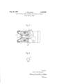
FIGURE 1 is a diagrammatic and fragmentary axial section showing the brake cylinder of this invention, and
FIGURE 2 is a plane view of one of the spring rings of the play take-up device incorporated in this cylinder.
The brake cylinder illustrated comprises a cylinder body 1 of a type conventional notably in drum brakes; this cylinder body is provided intermediate its ends with a port 2 for delivering fluid under pressure to the cylinder and with another port 3 receiving a drain plug.
In this cylinder and at the two ends thereof a pair of pistons are slidably mounted; only one piston 4 is visible in FIGURE 1, the two pistons of the pair forming therebetween and with the cylinder wall a chamber 5 with which said ports communicate.
Each piston 4 is insealed and sliding engagement with the cylinder wall by means of a packing 6, and is connected to the adjacent end of cylinder 1 by means of a protection cup 7, and the central portion 8 of its outer face constitutes a thrust face engageable by a brake shoe of conventional type (not shown).
The play take-up device incorporated in the brake cylinder comprises a rod 10 fitting freely in a corresponding cavity of piston 4, this rod being either rigid with the opposite piston or mounted therein in the same manner as in piston 4 illustrated in the figure, together, in this case, with all the component elements of the play take-up device which are disclosed hereinafter.
On the rod 10 and in a cavity 11 formed in the piston 4 a plurality of split spring rings or circlips 12, here four 'in number are fitted with a radial inward contraction.
These rings 12 may be of any suitable commercially available type and conventionally used as retaining or assembly members, such as the circlip rings known under the trademark Truarc and the trade name Grip-Ring.
These rings 12 co-act in the axial direction at one end with a shoulder stop 13 forming the bottom of said cavity 11 and at the opposite end a washer 14 associated with these rings 12 is adapted to engage an abutment ring 15 resiliently fitted in a internal groove formed in said cavity 11.
In this example, the free mounting of the rod 10 in piston 4 is such that any undesired trapping of control fluid between the end of this rod and the bottom of said cavity is definitely precluded.
The axial play E of said rings 12 and washer 14 between the shoulder stop 13 and the abutment ring 15 corresponds to the permissible return play of piston 4 when the brake is released. This return movement is produced by the elastic return means associated with the brake (not shown) and the frictional effort due to the engagement between the rings 12 and rod 10 is calculated to be somewhat higher than this return effort; in other words, the rings 12 act as a piston stop during a brake release, whereby the inoperative position of the brake control means is that shown in FIGURE 1. On the other hand, this frictional effort obtained between said rings 12 and said rod 10 is definitely inferior to the effort likely to be applied 'by the fluid under pressure to the piston 4, and if for any reason the piston stroke'E were not sufficient during a brake application, for example as a consequence of the gradual wearing of the brake linings, the piston 4 will easily carry along, through the medium of the abutment ring 15 and washer 14, the set of spring rings 12 which, in this case, will slide axially along the rod 10.
However, this movement of rings 12 is reversible in case of an effort exceeding that exerted by the elastic brake return means and may easily be produced without resorting to any particular operation in case of replacement of worn linings or, as already suggested hereinabove, when the brake cools down after a considerable overheating having determined a control movement tending to produce a residual braking effect on cooling.
Of course, the number of spring rings 12 depends on the nature of the ring or rings used in the brake cylinder and on the effort contemplated for returning the brake concerned to its release position, the ring or rings being in all cases such that the frictional engagement between these rings and the rod will generate the same mechanical frictional resistance in either direction.
On the other hand, if it is desired to limit the value of the permissible slipping stroke of the ring or rings 12 on said rod 10, a groove 9 will be formed in the outer end of this rod for engagement by the ring or the outermost ring if several rings 12 are provided. Advantageously the inner face of this groove 9 which is opposite to the ring will extend substantialy at right angles to the axis of rod 10, and the other inner face of the groove 9 will be substantially frustoconical or tapered, as shown; thus, the stopping action of this groove will be unidirectional, the ring having the possibility of escaping from this groove by slipping on said tapered side face.
Of course, in the more frequent case where the device comprises two pistons and two rings or sets of rings disposed symmetrically, this groove 9 is formed in both ends of the rod 10. Thus, the extreme movement of one or the other of these rings or sets of rings 12 along the rod 10 cannot take place except if for any reason an asymmetric condition developed in the operation of the device. Thus, the groove 9 will protect the device against possible damages.
What is claimed is:
A brake cylinder with built-in, self-adjustment means comprising at least one piston slidably and sealingly fitted in said cylinder with the return play thereof being limited by said adjustment means, a bore in said piston, two stops provided in said bore with a spacing equal to the aforesaid play, a rod disposed internally of said cylinder and extending into said bore, at least one split ring clamped on said rod between said stops, the frictional effort pr0 duced by the engagement between said ring and said rod being such that said ring may be easily moved along said rod by said piston during brake application but will resist the return effort exerted the brake return means on said piston during brake release, an annular groove adjacent the end of said rod along which said ring is adapted to slide, said groove having a width greater than the thickness of said ring, the side wall of said groove adjacent the end of the rod extending at right angles to the axis of the rod, the other wall of said groove being substantially of a frustoconical configuration with the smaller base being adjacent said flat side wall.
References Cited UNITED STATES PATENTS 2,844,223 7/1958 Runner 18872 X 2,957,551 10/1960 Nahodil 188196 X 3,200,911 8/1965 Rumelin 188196 FOREIGN PATENTS 76,776 10/1961 France.
(1st addition to No. 1,227,387) 937,781 9/1963 Great Britain.
DUANE A. REGER, Primary Examiner.
Applications Claiming Priority (1)
| Application Number | Priority Date | Filing Date | Title |
|---|---|---|---|
| FR981882A FR1409409A (en) | 1964-07-16 | 1964-07-16 | Brake control cylinder with automatic slack adjustment device |
Publications (1)
| Publication Number | Publication Date |
|---|---|
| US3338352A true US3338352A (en) | 1967-08-29 |
Family
ID=8834670
Family Applications (1)
| Application Number | Title | Priority Date | Filing Date |
|---|---|---|---|
| US462920A Expired - Lifetime US3338352A (en) | 1964-07-16 | 1965-06-10 | Self-adjusting brake cylinder for automotive vehicle |
Country Status (8)
| Country | Link |
|---|---|
| US (1) | US3338352A (en) |
| BE (1) | BE665736A (en) |
| DE (1) | DE1265510B (en) |
| FR (1) | FR1409409A (en) |
| GB (1) | GB1103024A (en) |
| LU (1) | LU49009A1 (en) |
| NL (1) | NL140944B (en) |
| SE (1) | SE334782B (en) |
Cited By (6)
| Publication number | Priority date | Publication date | Assignee | Title |
|---|---|---|---|---|
| US3467226A (en) * | 1966-07-28 | 1969-09-16 | Teves Kg Alfred | Wheel-brake cylinder adjuster |
| US3502180A (en) * | 1966-12-28 | 1970-03-24 | Aisin Seiki | Automatic device for adjusting brake clearance for vehicles |
| US3952841A (en) * | 1973-10-29 | 1976-04-27 | United States Steel Corporation | Disc brake wear take-up |
| FR2441767A1 (en) * | 1978-11-14 | 1980-06-13 | Lucas Industries Ltd | IMPROVEMENTS ON EXTENSION DISC BRAKES FOR VEHICLES |
| EP0267694A1 (en) * | 1986-11-05 | 1988-05-18 | LUCAS INDUSTRIES public limited company | Improvements in hydraulically-operated actuator assemblies for vehicle brakes |
| US5080202A (en) * | 1989-05-11 | 1992-01-14 | Bendix Altecna S.P.A. | Wheel cylinder |
Families Citing this family (2)
| Publication number | Priority date | Publication date | Assignee | Title |
|---|---|---|---|---|
| CH599481A5 (en) * | 1975-12-22 | 1978-05-31 | Inventio Ag | |
| DE2842433C2 (en) * | 1978-09-29 | 1984-06-07 | Alfred Teves Gmbh, 6000 Frankfurt | Automatic friction adjustment |
Citations (6)
| Publication number | Priority date | Publication date | Assignee | Title |
|---|---|---|---|---|
| US2844223A (en) * | 1955-08-01 | 1958-07-22 | Goodyear Tire & Rubber | Automatic adjustment grip for brakes |
| FR1227387A (en) * | 1959-03-04 | 1960-08-19 | Actuating device with cylinder and piston and pressurized fluid | |
| US2957551A (en) * | 1956-11-07 | 1960-10-25 | Zapadoceske Autodruzstvo | Apparatus for effecting automatic adjustment of the clearance between the brake lining and the brake friction surface in fluid operated brakes |
| FR76776E (en) * | 1959-12-16 | 1961-12-01 | Actuating device with cylinder and piston and pressurized fluid | |
| GB937781A (en) * | 1959-02-11 | 1963-09-25 | Heinz Teves | Improvements in or relating to the automatic adjustment of fluid-pressure operated vehicle brakes |
| US3200911A (en) * | 1960-11-16 | 1965-08-17 | Teves Kg Alfred | Hydraulic cylinder assembly for disc brakes |
Family Cites Families (8)
| Publication number | Priority date | Publication date | Assignee | Title |
|---|---|---|---|---|
| US2747694A (en) * | 1951-04-05 | 1956-05-29 | Gen Motors Corp | Brake wear compensator |
| FR1140480A (en) * | 1954-12-20 | 1957-07-23 | Bendix Aviat Corp | Braking mechanism |
| FR1150254A (en) * | 1955-10-06 | 1958-01-09 | Goodyear Tire & Rubber | Self-adjusting brake |
| US2866526A (en) * | 1955-10-06 | 1958-12-30 | Goodyear Tire & Rubber | Automatic brake adjustment |
| FR1244756A (en) * | 1959-01-07 | 1960-10-28 | Dunlop Sa | Disc brake improvements |
| FR1160808A (en) * | 1959-02-13 | 1958-08-11 | Dunlop Sa | Automatic adjustment device for brakes, clutches and the like |
| FR75495E (en) * | 1959-03-17 | 1961-06-30 | Rech Etudes Prod | Device for the automatic take-up of wear of various components, such as friction linings |
| FR1266506A (en) * | 1960-05-24 | 1961-07-17 | Bendix Corp | Automatic brake adjuster |
-
1964
- 1964-07-16 FR FR981882A patent/FR1409409A/en not_active Expired
-
1965
- 1965-06-10 GB GB24594/65A patent/GB1103024A/en not_active Expired
- 1965-06-10 US US462920A patent/US3338352A/en not_active Expired - Lifetime
- 1965-06-21 BE BE665736D patent/BE665736A/xx unknown
- 1965-06-28 NL NL656508277A patent/NL140944B/en not_active IP Right Cessation
- 1965-07-07 LU LU49009A patent/LU49009A1/xx unknown
- 1965-07-14 SE SE09270/65A patent/SE334782B/xx unknown
- 1965-07-15 DE DEA49751A patent/DE1265510B/en not_active Withdrawn
Patent Citations (6)
| Publication number | Priority date | Publication date | Assignee | Title |
|---|---|---|---|---|
| US2844223A (en) * | 1955-08-01 | 1958-07-22 | Goodyear Tire & Rubber | Automatic adjustment grip for brakes |
| US2957551A (en) * | 1956-11-07 | 1960-10-25 | Zapadoceske Autodruzstvo | Apparatus for effecting automatic adjustment of the clearance between the brake lining and the brake friction surface in fluid operated brakes |
| GB937781A (en) * | 1959-02-11 | 1963-09-25 | Heinz Teves | Improvements in or relating to the automatic adjustment of fluid-pressure operated vehicle brakes |
| FR1227387A (en) * | 1959-03-04 | 1960-08-19 | Actuating device with cylinder and piston and pressurized fluid | |
| FR76776E (en) * | 1959-12-16 | 1961-12-01 | Actuating device with cylinder and piston and pressurized fluid | |
| US3200911A (en) * | 1960-11-16 | 1965-08-17 | Teves Kg Alfred | Hydraulic cylinder assembly for disc brakes |
Cited By (7)
| Publication number | Priority date | Publication date | Assignee | Title |
|---|---|---|---|---|
| US3467226A (en) * | 1966-07-28 | 1969-09-16 | Teves Kg Alfred | Wheel-brake cylinder adjuster |
| US3502180A (en) * | 1966-12-28 | 1970-03-24 | Aisin Seiki | Automatic device for adjusting brake clearance for vehicles |
| US3952841A (en) * | 1973-10-29 | 1976-04-27 | United States Steel Corporation | Disc brake wear take-up |
| FR2441767A1 (en) * | 1978-11-14 | 1980-06-13 | Lucas Industries Ltd | IMPROVEMENTS ON EXTENSION DISC BRAKES FOR VEHICLES |
| US4276963A (en) * | 1978-11-14 | 1981-07-07 | Lucas Industries Limited | Spreading disc brakes for vehicles |
| EP0267694A1 (en) * | 1986-11-05 | 1988-05-18 | LUCAS INDUSTRIES public limited company | Improvements in hydraulically-operated actuator assemblies for vehicle brakes |
| US5080202A (en) * | 1989-05-11 | 1992-01-14 | Bendix Altecna S.P.A. | Wheel cylinder |
Also Published As
| Publication number | Publication date |
|---|---|
| LU49009A1 (en) | 1965-09-07 |
| BE665736A (en) | 1965-10-18 |
| GB1103024A (en) | 1968-02-14 |
| NL6508277A (en) | 1966-01-17 |
| DE1265510B (en) | 1968-04-04 |
| SE334782B (en) | 1971-05-03 |
| NL140944B (en) | 1974-01-15 |
| FR1409409A (en) | 1965-08-27 |
Similar Documents
| Publication | Publication Date | Title |
|---|---|---|
| US4436186A (en) | Disc brake assembly | |
| US3186521A (en) | Automatic adjusting devices for brake actuating mechanisms | |
| US4458790A (en) | Caliper mounting suspension | |
| US4375842A (en) | Disc brake caliper piston and housing retraction and knockback control mechanism | |
| US3277983A (en) | Compensating brake structure | |
| US5443141A (en) | Pressure-controlled readjusting device for a vehicle brake | |
| GB940769A (en) | Disc brake | |
| US2175446A (en) | Slack adjuster | |
| JP6723218B2 (en) | Assembly with device to move the pad away from the brake disc | |
| US4161239A (en) | Disc brake | |
| US2997137A (en) | Automatic adjustment devices for brakes | |
| GB1443013A (en) | Disc brake caliper assemblies | |
| US3885653A (en) | Brake Adjusters | |
| US3064768A (en) | Automatic brake adjusting mechanism | |
| US4050548A (en) | Automatic adjusters for hydraulically operated disc brakes | |
| GB2148425A (en) | Improvements in hydraulic actuator assemblies for vehicle brakes | |
| US4386682A (en) | Piston retraction and wear compensation for low-drag disc brakes | |
| US2657773A (en) | Automatic brake adjustment | |
| US2952338A (en) | Hydraulic brake actuating mechanism | |
| US2997138A (en) | Wear compensating brake | |
| US3860095A (en) | Vehicle brakes | |
| GB1494221A (en) | Brake adjusters | |
| US4685542A (en) | Disc brake assembly | |
| US3589479A (en) | Brake retractor mechanism | |
| US3032144A (en) | Combination adjuster and reset mechanism |