US3338425A - Center gudgeon adjustment means - Google Patents
Center gudgeon adjustment means Download PDFInfo
- Publication number
- US3338425A US3338425A US488096A US48809665A US3338425A US 3338425 A US3338425 A US 3338425A US 488096 A US488096 A US 488096A US 48809665 A US48809665 A US 48809665A US 3338425 A US3338425 A US 3338425A
- Authority
- US
- United States
- Prior art keywords
- gudgeon
- car body
- frame
- section
- upper section
- Prior art date
- Legal status (The legal status is an assumption and is not a legal conclusion. Google has not performed a legal analysis and makes no representation as to the accuracy of the status listed.)
- Expired - Lifetime
Links
- 241001125877 Gobio gobio Species 0.000 title 1
- 241001125879 Gobio Species 0.000 claims description 63
- 229910000831 Steel Inorganic materials 0.000 description 9
- 239000010959 steel Substances 0.000 description 9
- 239000004519 grease Substances 0.000 description 5
- 238000005461 lubrication Methods 0.000 description 4
- 239000000463 material Substances 0.000 description 4
- 230000001050 lubricating effect Effects 0.000 description 3
- 239000011435 rock Substances 0.000 description 2
- 229910000906 Bronze Inorganic materials 0.000 description 1
- 239000010974 bronze Substances 0.000 description 1
- 230000000295 complement effect Effects 0.000 description 1
- 238000010276 construction Methods 0.000 description 1
- KUNSUQLRTQLHQQ-UHFFFAOYSA-N copper tin Chemical compound [Cu].[Sn] KUNSUQLRTQLHQQ-UHFFFAOYSA-N 0.000 description 1
- 230000008030 elimination Effects 0.000 description 1
- 238000003379 elimination reaction Methods 0.000 description 1
- 238000012423 maintenance Methods 0.000 description 1
- 230000002093 peripheral effect Effects 0.000 description 1
- 230000009467 reduction Effects 0.000 description 1
Images

Classifications
-
- B—PERFORMING OPERATIONS; TRANSPORTING
- B66—HOISTING; LIFTING; HAULING
- B66C—CRANES; LOAD-ENGAGING ELEMENTS OR DEVICES FOR CRANES, CAPSTANS, WINCHES, OR TACKLES
- B66C23/00—Cranes comprising essentially a beam, boom, or triangular structure acting as a cantilever and mounted for translatory of swinging movements in vertical or horizontal planes or a combination of such movements, e.g. jib-cranes, derricks, tower cranes
- B66C23/62—Constructional features or details
- B66C23/84—Slewing gear
-
- E—FIXED CONSTRUCTIONS
- E02—HYDRAULIC ENGINEERING; FOUNDATIONS; SOIL SHIFTING
- E02F—DREDGING; SOIL-SHIFTING
- E02F9/00—Component parts of dredgers or soil-shifting machines, not restricted to one of the kinds covered by groups E02F3/00 - E02F7/00
- E02F9/08—Superstructures; Supports for superstructures
- E02F9/10—Supports for movable superstructures mounted on travelling or walking gears or on other superstructures
- E02F9/12—Slewing or traversing gears
- E02F9/121—Turntables, i.e. structure rotatable about 360°
Definitions
- a vertically extending center gudgeon holds the revolvable upper section firmly and accurately on the lower car body and is provided with means of adjustment to maintain the proper vertical running clearance whereby the upper section can rotate smoothly on the car body.
- the gudgeon and hub in the car body are originally shrinkfitted together, but as the various bearing surfaces and thrust washers wear, the gudgeon must be adjusted or tightened to eliminate any looseness or backlash. In other words, the upper section will begin to rock due to this wear and it is imperative to prevent this rock. It is to this problem of adjusting the gudgeon that the present invention is directed.
- Another aspect relates to means for conveniently lifting the gudgeon up in its mounting for replacement of the spherical thrust washer at the upper end of the gudgeon.
- Another object of the invention is to provide a power shovel or the like having an improved mounting means for the upper end of a center gudgeon.
- FIGURE 1 is a perspective view of a power shovel embodying the present invention
- FIGURE 2 is a perspective view of the lower section or car body of the shovel shown in FIGURE 1;
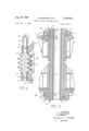
- FIGURE 3 is an enlarged, vertical, cross sectional view through the center gudgeon shown in FIGURES 1 and 2;
- FIGURE 4 is a horizontal, sectional view taken along line 4-4 in FIGURE 3;
- FIGURE 5 is a cross section taken along line 5-5 in FIGURE 2.
- the upper section 1 of the shovel is rotatably mounted on the lower car body 2 about the vertical axis formed by the center gudgeon 3 and is supported on the anti-friction roller circle 4 in the known manner.
- the lower car body 2 includes the heavy steel frame 5 in which is welded the vertically extending tubular hub 6.
- the upper section 1 includes a heavy steel frame 8 in which is welded the vertical hub or sleeve 9.
- the tubular center gudgeon 3 extends through hub 6 to frame 5 by bolt means 36.
- a cup member 20 surrounds the gudgeon and extends upwardly above the spherical surface 13a of the thrust washer 13 whereby lubricating grease can be supplied via inlet 22 to a space 23 above a bearing sleeve 24.
- Grease grooves 25 and 26 are formed in the upper and lower surfaces, respectively, of the washer 13. In this manner a continuous supply of grease is provided for both surfaces of the ring 13 and also the sleeve 24.
- Radial holes 27 also act to convey grease.
- a removable shield 28 is mounted on a ledge 29 on the top of the thrust ring and which extends radially beyond the vertical sleeve 20 to prevent entry of foreign matter into the assembly. This shield forms an overhanging portion beneath which the cup member 20 extends to substantially enclose the washer.
- the lubrication fitting was incorporated in the center gudgeon and had to be hand serviced independently from any centralized or automatic lubrication since its location in respect to the revolving upper constantly changed as the upper revolved around the stationary center gudgeon.
- the new grease arrangement can be connected to any automatic lubrication system. Elimination of adjustment and lubrication on top end of the gudgeon is important from safety and maintenance standpoint especially since the area immediately above the center gudgeon is occupied by the high voltage collector system (not shown) which carries high voltage from the ground cable to the revolving upper.
- a large nut 32 is threaded on the lower end of the gudgeon 3 and its outer peripheral portion is formed as a gear 33 for constant mesh with a worm gear 34 which extends normally to the gudgeon.
- the worm 34 is rotatably journalled in a bracket 35 which is fixed More specifically, the worm is journalled in split bearings 37 and 38 which are integral pants of the bracket 35 and the bores of the bearing are slightly undersized.
- the means for turning the adjusting worm 34 is shown as comprising a square end 42 on the worm which can be conveniently engaged by a ratchet wrench 43, notwithstanding the cramped quarters for making this adjustment.
- the lowermost end of the gudgeon is splined to the internal spline 44 of the bracket 35. This spline connection locks the gudgeon against turning in respect to lower frame 5.
- a conveniently placed limit gauge 46 is mounted at the lower edge of bracket 35 for checking wear and ultimate replacement of spherical washer 13 by observing the distance between the lower edge of the gudgeon and the edge of the indicator.
- Any suitable means may be provided for turning the worm such as a hand ratchet 43, or this can be automated by means of any torque arrangement, such as hydraulic, air, or electric torque motors with proper gear reductions or reciprocating means such as electric solenoids, air or hydraulic rams with the proper ratchet arrangements.
- torque arrangement such as hydraulic, air, or electric torque motors with proper gear reductions or reciprocating means such as electric solenoids, air or hydraulic rams with the proper ratchet arrangements.
- a power shovel or the like comprising a lower car body and an upper revolvable section having an earth working tool mounted thereon, said car body and upper section each having a steel frame, an anti-friction roller circle mounted between said frames for supporting said revolvable section on said car body, a tubular center gudgeon extending through said frames and having a thrust ring at its upper end and extending radially therefrom and supported on said upper section frame, said gudgeon having an adjusting nut means threadably engaged on its lower end and bearing against said car body frame for drawing the upper section down tightly on said roller circle and against said car body, said nut means including a gear portion, a worm gear rotatably carried by said lower frame and in mesh with said gear portion, and means for adjustment of said worm gear and consequent adjustment of said nut on said gudgeon.
- each frame has a vertically disposed tubular hub welded therein and in axial alignment with one another, and said center gudgeon extends through said hubs.
- a shovel as defined in claim 1 including a thrust washer carried on the upper section frame and located directly beneath said ring, said ring bearing on said washer for support thereby.
- a shovel as defined in claim 1 including a bracket mounted on said car body frame and through which the lower end of said gudgeon extends, and a vertical spline connection between said bracket and said gudgeon lower end for preventing turning of said gudgeon relative to said car body frame, said worm gear being carried on said bracket.
- a power shovel or the like comprising a lower car body and an upper revolvable section having an earth working tool mounted thereon, said car body and upper section each having a steel frame, and anti-friction roller circle mounted between said frames for supporting said revolvable section on said car body, said frames each having a vertically disposed tubular hub in vertical alignment with one another, a tubular center gudgeon extending through said hubs and having a thrust ring at its upper end and extending radially therefrom, a thrust washer carried on the upper section frame and located directly beneath said ring, said ring bearing on said washer for support thereby, said gudgeon having an adjusting nut threadably engaged on its lower end and bearing against said car body frame for drawing the upper section down tightly on said roller circle and against said car body, said nut having a gear portion, a worm gear rotatably carried by said lower frame and in constant mesh with said gear portion, and means for adjustment of said worm gear and consequent adjustment of said nut on said gudgeon.
- a power shovel or the like comprising a lower car body and an upper revolvable section having an earth working tool mounted thereon, said car body and upper section each having a steel frame, an anti-friction roller circle mounted between said frames for supporting said revolvable section on said car body, a tubular center gudgeon extending through said frames and having a thrust ring at its upper end and extending radially therefrom, a thrust washer carried on the upper section frame and located directly beneath said ring, said ring bearing on said washer for support thereby, said gudgeon having an adjusting nut threadably engaged on its lower end and bearing against said car body frame for drawing the upper section down tightly on said roller circle and against said car body, a bracket mounted on said car body frame and through which the lower end of said gudgeon extends, a vertical spline connection between said bracket and said gudgeon lower end for preventing turning of said gudgeon relative to said car body frame, said nut having a gear portion, a worm gear rotat
- a power shovel or the like comprising a lower car body and an upper revolvable section having an earth working tool mounted thereon, said car body and upper section each having a steel frame, an anti-friction roller circle mounted between said frames for supporting said revolvable section on said car body, said frames each having a vertically disposed tubular hub in vertical alignment which one another, a tubular center gudgeon extending through said hubs and having a thrust ring at its upper end and extending radially therefrom and supported on said upper section frame, said gudgeon having an adjusting nut threadably engaged on its lower end and bearing against said car body frame for drawing the upper section down tightly on said roller circle and against said car body, a bracket mounted on said car body frame and through which the lower end of said gudgeon extends, a vertical spline connection between said bracket and said gudgeon lower end for preventing turning of said gudgeon relative to said car body frame, said nut having a gear portion, a worm gear rotatably carried
- a power shovel or the like comprising a lower car body and an upper revolvable section having an earth working tool mounted thereon, said car body and upper section each having a steel frame, an anti-friction roller circle mounted between said frames for supporting said revolvable section on said car body, said frames each having a vertically disposed tubular hub in vertical alignment with one another, a tubular center gudgeon extending through said hubs and having a thrust ring at its upper end and extending radially therefrom, a bearing sleeve between said gudgeon and the upper section frame hub, a thrust washer carried on the upper section frame hub and located directly beneath said ring, said ring bearing on said washer for support thereby and having a radially overhanging portion over said washer, and a cup member around said gudgeon and beneath said washer and extending upwardly beneath said overhanging portion to thereby substantially enclose said washer and ring and retain lubricating material therebetween and permit said material to lubricate said bearing slee
- a power shovel or the like comprising a lower car body and an upper revolvable section having an earth working tool mounted thereon, said car body and upper section each having a steel frame, an anti-friction roller circle mounted between said frames for supporting said revolvable section on said car body, said frames each having a vertically disposed tubular hub in vertical align *"ment with one another, a tubular center gudgeon extending through said hubs and having a thrust ring at its upper end and extending radially therefrom, a bearing sleeve between said gudgeon and the upper section frame hub, a thrust washer carried on the upper section frame hub and located directly beneath said ring, said ring bearing on said washer for support thereby and having a radially overhanging portion over said Washer, a cup member around said gudgeon and beneath said washer and extending upwardly beneath said overhanging portion to thereby substantially enclose said Washer and ring and retain lubricating material therebetween and permit said material to lubricate said bearing
Landscapes
- Engineering & Computer Science (AREA)
- Mechanical Engineering (AREA)
- Mining & Mineral Resources (AREA)
- Civil Engineering (AREA)
- General Engineering & Computer Science (AREA)
- Structural Engineering (AREA)
- Mounting Of Bearings Or Others (AREA)
Description
g- 29, 1957 K. SCHNEIDER ETAL. 3,338,425
CENTER GUDGEON ADJUSTMENT MEANS 2 Sheets-Sheet 1 Filed Sept. 17.. 1965 INVENTORSZ K Sam/505R /7( A. Bnpo/v 4fTOR/VEY g 29, 1967 K. SCHNEIDER ETAL 3,338,425
CENTER GUDGEON ADJUSTMENT MEANS Filed Sept. 17, 1965 2 Sheets-Sheet A Ill we y mw w HE R w m .MMA 55 4 .4 H
United States Patent O 3,338,425 CENTER GUDGEON ADJUSTMENT MEANS Karl Schneider and Henry A. Baron, Greendale, WlS., assignors to Harnischfeger Corporation, Milwaukee, Wis., a corporation of Wisconsin Filed Sept. 17, 1965, Ser. No. 488,096 9 Claims. (Cl. 212-66) The present invention relates generally to earth working equipment such as power excavators, shovels, draglines, cranes and the like. Equipment of this type has a lower car body with an endless track (crawler) section on which is rotatably mounted the upper section containing the shovel attachment and necessary machinery.
A vertically extending center gudgeon holds the revolvable upper section firmly and accurately on the lower car body and is provided with means of adjustment to maintain the proper vertical running clearance whereby the upper section can rotate smoothly on the car body. The gudgeon and hub in the car body are originally shrinkfitted together, but as the various bearing surfaces and thrust washers wear, the gudgeon must be adjusted or tightened to eliminate any looseness or backlash. In other words, the upper section will begin to rock due to this wear and it is imperative to prevent this rock. It is to this problem of adjusting the gudgeon that the present invention is directed.
Since the thrust faces of the assembly are subjected to considerable vertical loading during the digging cycle the resulting wear must be properly and promptly compensated for to prevent excessive rocking of the upper section on the lower car body and consequent shockloading on the two units and the center gudgeon itself. Simple and effective means must be found to induce the operator to make proper adjustment without delay.
It is accordingly an object of the present invention to provide a power shovel or the like having an improved adjustment means located at the lower end of the gudgeon for adjusting the latter without disturbing the upper end of the gudgeon assembly, said adjustment being made in a relatively convenient and accurate manner.
Another aspect relates to means for conveniently lifting the gudgeon up in its mounting for replacement of the spherical thrust washer at the upper end of the gudgeon.
Another object of the invention is to provide a power shovel or the like having an improved mounting means for the upper end of a center gudgeon.
Other objects and advantages of the invention will appear hereinafter as this disclosure progresses, reference being had to the accompanying drawings, in which:
FIGURE 1 is a perspective view of a power shovel embodying the present invention;
FIGURE 2 is a perspective view of the lower section or car body of the shovel shown in FIGURE 1; I
FIGURE 3 is an enlarged, vertical, cross sectional view through the center gudgeon shown in FIGURES 1 and 2;
FIGURE 4 is a horizontal, sectional view taken along line 4-4 in FIGURE 3;
FIGURE 5 is a cross section taken along line 5-5 in FIGURE 2.
Referring in greater detail to the drawings, the upper section 1 of the shovel is rotatably mounted on the lower car body 2 about the vertical axis formed by the center gudgeon 3 and is supported on the anti-friction roller circle 4 in the known manner.
The lower car body 2 includes the heavy steel frame 5 in which is welded the vertically extending tubular hub 6.
The upper section 1 includes a heavy steel frame 8 in which is welded the vertical hub or sleeve 9.
The tubular center gudgeon 3 extends through hub 6 to frame 5 by bolt means 36.
3,338,425 Patented Aug. 29, 1967 and sleeve 9 and has a radial shoulder 10 formed integrally on its upper end to which is welded the steel thrust ring 11. Ring 11 is generally of inverted cup shape so as to fit over and complement the spherical thrust washer 13 on which it rests. A recess 14 is formed in the upper end of sleeve 9 and a plate 15 sets in this recess. The washer 13 is of the split type, being formed in halves which also set in the recess 14 and are thereby held to gether. Washer 13 rests on plate 15 which in turn is fixed by dowel pins 19 to the sleeve 9.
A cup member 20 surrounds the gudgeon and extends upwardly above the spherical surface 13a of the thrust washer 13 whereby lubricating grease can be supplied via inlet 22 to a space 23 above a bearing sleeve 24. Grease grooves 25 and 26 are formed in the upper and lower surfaces, respectively, of the washer 13. In this manner a continuous supply of grease is provided for both surfaces of the ring 13 and also the sleeve 24. Radial holes 27 also act to convey grease.
It will also be noted that a removable shield 28 is mounted on a ledge 29 on the top of the thrust ring and which extends radially beyond the vertical sleeve 20 to prevent entry of foreign matter into the assembly. This shield forms an overhanging portion beneath which the cup member 20 extends to substantially enclose the washer.
Heretofore, the lubrication fitting was incorporated in the center gudgeon and had to be hand serviced independently from any centralized or automatic lubrication since its location in respect to the revolving upper constantly changed as the upper revolved around the stationary center gudgeon. The new grease arrangement can be connected to any automatic lubrication system. Elimination of adjustment and lubrication on top end of the gudgeon is important from safety and maintenance standpoint especially since the area immediately above the center gudgeon is occupied by the high voltage collector system (not shown) which carries high voltage from the ground cable to the revolving upper.
Referring now .to the area adjacent the lower end of the gudgeon, a large nut 32 is threaded on the lower end of the gudgeon 3 and its outer peripheral portion is formed as a gear 33 for constant mesh with a worm gear 34 which extends normally to the gudgeon. The worm 34 is rotatably journalled in a bracket 35 which is fixed More specifically, the worm is journalled in split bearings 37 and 38 which are integral pants of the bracket 35 and the bores of the bearing are slightly undersized.
Thus by tightening the cap screws 39 which extend into the bracket the worm pinion assembly can be locked in adjusted position. Furthermore, due to the split construction of the bearings, it is possible to use a one piece Worm pinion and a one piece bronze thrust washer 40 on each end.
In addition, the actual center distance between the Worm 3'4 and the gear portion 33 of the nut 32 is reduced rom the theoretical distance so that by tightening the bearings caps, further locking or clamping action of the assembly is provided.
The means for turning the adjusting worm 34 is shown as comprising a square end 42 on the worm which can be conveniently engaged by a ratchet wrench 43, notwithstanding the cramped quarters for making this adjustment.
The lowermost end of the gudgeon is splined to the internal spline 44 of the bracket 35. This spline connection locks the gudgeon against turning in respect to lower frame 5.
Only a minimum clearance between the lower edge of nut 32 and the adjoining surface of bracket 35 is provided. By reversing the rotation of the worm, the center 3 gudgeon can be raised for the purpose of replacing the upper split spherical thrust washer 13.
A conveniently placed limit gauge 46 is mounted at the lower edge of bracket 35 for checking wear and ultimate replacement of spherical washer 13 by observing the distance between the lower edge of the gudgeon and the edge of the indicator.
Any suitable means may be provided for turning the worm such as a hand ratchet 43, or this can be automated by means of any torque arrangement, such as hydraulic, air, or electric torque motors with proper gear reductions or reciprocating means such as electric solenoids, air or hydraulic rams with the proper ratchet arrangements.
In order to remove the split washer 13 when worn, it is only necessary to lift shield 28 and cup member 20 off the assembly and then turn the worm 34 to raise the gudgeon sufficiently to be able to lift the halves of the washer 13 and pull them in a radial direction and clear of the gudgeon.
Various modes of carrying out the invention are contemplated as being within the scope of the following claims particularly pointing out and distinctly claiming the subject matter which is regarded as the invention:
- We claim:
1. A power shovel or the like comprising a lower car body and an upper revolvable section having an earth working tool mounted thereon, said car body and upper section each having a steel frame, an anti-friction roller circle mounted between said frames for supporting said revolvable section on said car body, a tubular center gudgeon extending through said frames and having a thrust ring at its upper end and extending radially therefrom and supported on said upper section frame, said gudgeon having an adjusting nut means threadably engaged on its lower end and bearing against said car body frame for drawing the upper section down tightly on said roller circle and against said car body, said nut means including a gear portion, a worm gear rotatably carried by said lower frame and in mesh with said gear portion, and means for adjustment of said worm gear and consequent adjustment of said nut on said gudgeon.
2. A shovel as defined in claim 1 further characterized in that each frame has a vertically disposed tubular hub welded therein and in axial alignment with one another, and said center gudgeon extends through said hubs.
3. A shovel as defined in claim 1 including a thrust washer carried on the upper section frame and located directly beneath said ring, said ring bearing on said washer for support thereby.
4. A shovel as defined in claim 1 including a bracket mounted on said car body frame and through which the lower end of said gudgeon extends, and a vertical spline connection between said bracket and said gudgeon lower end for preventing turning of said gudgeon relative to said car body frame, said worm gear being carried on said bracket.
5. A power shovel or the like comprising a lower car body and an upper revolvable section having an earth working tool mounted thereon, said car body and upper section each having a steel frame, and anti-friction roller circle mounted between said frames for supporting said revolvable section on said car body, said frames each having a vertically disposed tubular hub in vertical alignment with one another, a tubular center gudgeon extending through said hubs and having a thrust ring at its upper end and extending radially therefrom, a thrust washer carried on the upper section frame and located directly beneath said ring, said ring bearing on said washer for support thereby, said gudgeon having an adjusting nut threadably engaged on its lower end and bearing against said car body frame for drawing the upper section down tightly on said roller circle and against said car body, said nut having a gear portion, a worm gear rotatably carried by said lower frame and in constant mesh with said gear portion, and means for adjustment of said worm gear and consequent adjustment of said nut on said gudgeon.
6. A power shovel or the like comprising a lower car body and an upper revolvable section having an earth working tool mounted thereon, said car body and upper section each having a steel frame, an anti-friction roller circle mounted between said frames for supporting said revolvable section on said car body, a tubular center gudgeon extending through said frames and having a thrust ring at its upper end and extending radially therefrom, a thrust washer carried on the upper section frame and located directly beneath said ring, said ring bearing on said washer for support thereby, said gudgeon having an adjusting nut threadably engaged on its lower end and bearing against said car body frame for drawing the upper section down tightly on said roller circle and against said car body, a bracket mounted on said car body frame and through which the lower end of said gudgeon extends, a vertical spline connection between said bracket and said gudgeon lower end for preventing turning of said gudgeon relative to said car body frame, said nut having a gear portion, a worm gear rotatably carried by said bracket and in constant mesh with said gear portion, and means on said worm gear for adjustment thereof and consequent adjustment of said nut on said gudgeon.
7. A power shovel or the like comprising a lower car body and an upper revolvable section having an earth working tool mounted thereon, said car body and upper section each having a steel frame, an anti-friction roller circle mounted between said frames for supporting said revolvable section on said car body, said frames each having a vertically disposed tubular hub in vertical alignment which one another, a tubular center gudgeon extending through said hubs and having a thrust ring at its upper end and extending radially therefrom and supported on said upper section frame, said gudgeon having an adjusting nut threadably engaged on its lower end and bearing against said car body frame for drawing the upper section down tightly on said roller circle and against said car body, a bracket mounted on said car body frame and through which the lower end of said gudgeon extends, a vertical spline connection between said bracket and said gudgeon lower end for preventing turning of said gudgeon relative to said car body frame, said nut having a gear portion, a worm gear rotatably carried by said bracket and in constant mesh with said gear portion, and means on said worm gear for adjustment thereof and consequent adjustment of said nut on said gudgeon.
8. A power shovel or the like comprising a lower car body and an upper revolvable section having an earth working tool mounted thereon, said car body and upper section each having a steel frame, an anti-friction roller circle mounted between said frames for supporting said revolvable section on said car body, said frames each having a vertically disposed tubular hub in vertical alignment with one another, a tubular center gudgeon extending through said hubs and having a thrust ring at its upper end and extending radially therefrom, a bearing sleeve between said gudgeon and the upper section frame hub, a thrust washer carried on the upper section frame hub and located directly beneath said ring, said ring bearing on said washer for support thereby and having a radially overhanging portion over said washer, and a cup member around said gudgeon and beneath said washer and extending upwardly beneath said overhanging portion to thereby substantially enclose said washer and ring and retain lubricating material therebetween and permit said material to lubricate said bearing sleeve, said gudgeon having an adjusting nut threadably engaged on its lower end and bearing against said car body frame for drawing the upper section down tightly on said roller circle and against said car body.
9. A power shovel or the like comprising a lower car body and an upper revolvable section having an earth working tool mounted thereon, said car body and upper section each having a steel frame, an anti-friction roller circle mounted between said frames for supporting said revolvable section on said car body, said frames each having a vertically disposed tubular hub in vertical align *"ment with one another, a tubular center gudgeon extending through said hubs and having a thrust ring at its upper end and extending radially therefrom, a bearing sleeve between said gudgeon and the upper section frame hub, a thrust washer carried on the upper section frame hub and located directly beneath said ring, said ring bearing on said washer for support thereby and having a radially overhanging portion over said Washer, a cup member around said gudgeon and beneath said washer and extending upwardly beneath said overhanging portion to thereby substantially enclose said Washer and ring and retain lubricating material therebetween and permit said material to lubricate said bearing sleeve, said gudgeon having an adjusting nut threadably engaged on its lower end and bearing against said car body frame for drawing References Cited UNITED STATES PATENTS 1,572,134 2/1926 Fylsse 212-69 FOREIGN PATENTS 1,026,377 2/1953 Germany.
ANDRES H. NIELSEN, Primary Examiner.
Claims (1)
1. A POWER SHOVEL OR THE LIKE COMPRISING A LOWER CAR BODY AND AN UPPER REVOLVABLE SECTION HAVING AN EARTH WORKING TOOL MOUNTED THEREON, SAID CAR BODY AND UPPER SECTION EACH HAVING A STEEL FRAME, AN ANTI-FRICTION ROLLER CIRCLE MOUNTED BETWEEN SAID FRAMES FOR SUPPORTING SAID REVOLVABLE SECTION ON SAID CAR BODY, A TUBULAR CENTER GUDGEON EXTENDING THROUGH SAID FRAME AND HAVING A THRUST RING AT ITS UPPER END AND EXTENDING RADIALLY THEREFROM AND SUPPORTED ON SAID UPPER SECTION FRAME, SAID GUDGEON HAVING AN ADJUSTING NUT MEANS THREADABLY ENGAGED ON ITS LOWER END AND BEARING AGAINST SAID CAR BODY FRAME FOR DRAWING THE UPPER SECTION DOWN TIGHTLY ON SAID ROLLER CIRCLE AND AGAINST SAID CAR BODY, SAID NUT MEANS INCLUDING A GEAR PORTION, A WORM GEAR ROTATABLY CARRIED BY SAID LOWER FRAME AND IN MESH WITH SAID GEAR PORTION, AND MEANS FOR ADJUSTMENT OF SAID WORM GEAR AND CONSEQUENT ADJUSTMENT OF SAID NUT ON SAID GUDGEON.
Priority Applications (1)
| Application Number | Priority Date | Filing Date | Title |
|---|---|---|---|
| US488096A US3338425A (en) | 1965-09-17 | 1965-09-17 | Center gudgeon adjustment means |
Applications Claiming Priority (1)
| Application Number | Priority Date | Filing Date | Title |
|---|---|---|---|
| US488096A US3338425A (en) | 1965-09-17 | 1965-09-17 | Center gudgeon adjustment means |
Publications (1)
| Publication Number | Publication Date |
|---|---|
| US3338425A true US3338425A (en) | 1967-08-29 |
Family
ID=23938315
Family Applications (1)
| Application Number | Title | Priority Date | Filing Date |
|---|---|---|---|
| US488096A Expired - Lifetime US3338425A (en) | 1965-09-17 | 1965-09-17 | Center gudgeon adjustment means |
Country Status (1)
| Country | Link |
|---|---|
| US (1) | US3338425A (en) |
Cited By (3)
| Publication number | Priority date | Publication date | Assignee | Title |
|---|---|---|---|---|
| US4446977A (en) * | 1981-03-31 | 1984-05-08 | Mcdermott Incorporated | Roller support for load handling devices |
| CN102431916A (en) * | 2011-12-21 | 2012-05-02 | 上海三一科技有限公司 | Ring rail adjustable supporting device and crane comprising same |
| US9394944B2 (en) * | 2014-07-08 | 2016-07-19 | Caterpillar Global Mining Llc | Thrust rail and swing gear assembly for a mining vehicle |
Citations (2)
| Publication number | Priority date | Publication date | Assignee | Title |
|---|---|---|---|---|
| US1572134A (en) * | 1922-07-21 | 1926-02-09 | Bucyrus Co | Removable wheel |
| DE1026377B (en) * | 1956-02-20 | 1958-03-20 | Siemens Ag | Resettable running time tube arrangement |
-
1965
- 1965-09-17 US US488096A patent/US3338425A/en not_active Expired - Lifetime
Patent Citations (2)
| Publication number | Priority date | Publication date | Assignee | Title |
|---|---|---|---|---|
| US1572134A (en) * | 1922-07-21 | 1926-02-09 | Bucyrus Co | Removable wheel |
| DE1026377B (en) * | 1956-02-20 | 1958-03-20 | Siemens Ag | Resettable running time tube arrangement |
Cited By (4)
| Publication number | Priority date | Publication date | Assignee | Title |
|---|---|---|---|---|
| US4446977A (en) * | 1981-03-31 | 1984-05-08 | Mcdermott Incorporated | Roller support for load handling devices |
| CN102431916A (en) * | 2011-12-21 | 2012-05-02 | 上海三一科技有限公司 | Ring rail adjustable supporting device and crane comprising same |
| CN102431916B (en) * | 2011-12-21 | 2014-07-23 | 上海三一科技有限公司 | Ring rail adjustable supporting device and crane containing same |
| US9394944B2 (en) * | 2014-07-08 | 2016-07-19 | Caterpillar Global Mining Llc | Thrust rail and swing gear assembly for a mining vehicle |
Similar Documents
| Publication | Publication Date | Title |
|---|---|---|
| US3888357A (en) | Swing bearing with bolt-on segmented gear | |
| US20150135866A1 (en) | Sealed guard for motor grader draft apparatus | |
| DE2254435C3 (en) | Support for mobile cranes, excavators and the like. | |
| US3338425A (en) | Center gudgeon adjustment means | |
| DE19937784A1 (en) | Double-disc fine grinding machine | |
| US5310067A (en) | Compensating crane and method | |
| CN101532300B (en) | Swiveling mechanism and engineering machinery with swiveling mechanism | |
| CA2169018C (en) | Dragline with improved thrust bearing assembly supporting upper structure | |
| US3990539A (en) | Lubrication means for swing gear drive | |
| US20210332551A1 (en) | Work equipment for motor grader | |
| US4446977A (en) | Roller support for load handling devices | |
| EP1150039A2 (en) | Device for a turnable coupling of two co-axial connecting terminals | |
| DE2140110A1 (en) | Turntable drive | |
| DE2508001A1 (en) | DEVICE FOR SLIDING TWO ELEMENTS TOGETHER | |
| US2732641A (en) | Jespersen | |
| CN212769537U (en) | Special steel wire rope carrier roller for portal crane | |
| US4426964A (en) | Runner-type lubricating device for vertical engine | |
| EP3155895B1 (en) | Pillar suitable for forest machine | |
| US1635689A (en) | Turntable bearing device | |
| US11371208B2 (en) | Work equipment for motor grader | |
| DE2941921A1 (en) | SPACE SHIELD FOR ROLLING MOLDING MACHINES | |
| RU2608484C2 (en) | Mine excavator and its rotation and rolling support device | |
| US3080794A (en) | Turret type vertical milling machine | |
| EP3626039B1 (en) | Bearing arrangement and agricultural machine with this bearing arrangement | |
| CN219256957U (en) | Steering drive axle wheel side locking mechanism and engineering machinery |